Facile fabrication of a jarosite ultrathin KFe3(SO4)2(OH)6@rGO nanosheet hybrid composite with pseudocapacitive contribution as a robust anode for lithium-ion batteries†
Naiteng
Wu
 a,
Wendi
Tian
a,
Jinke
Shen
a,
Xiaoguang
Qiao
a,
Tao
Sun
a,
Wendi
Tian
a,
Jinke
Shen
a,
Xiaoguang
Qiao
a,
Tao
Sun
 a,
Hao
Wu
 b,
Jianguo
Zhao
c,
Xianming
Liu
*a and
Yun
Zhang
 *b
*b
aKey Laboratory of Function-oriented Porous Materials, College of Chemistry and Chemical Engineering, Luoyang Normal University, Luoyang, 471934, P. R. China. E-mail: myclxm@163.com
bCollege of Materials Science and Engineering, Sichuan University, Chengdu 610064, P. R. China. E-mail: y_zhang@scu.edu.cn
cSchool of Physical & Electronic Information, Luoyang Normal University, Luoyang, 471934, P. R. China
First published on 20th November 2018
Abstract
The search for anode materials with high performance and low cost for lithium-ion batteries (LIBs) remains challenging. Herein, Earth-abundant and acid-resistant jarosite ultrathin KFe3(SO4)2(OH)6@rGO (KFN@rGO) nanosheets were fabricated via a facile and scalable hydrothermal route without any surfactant. When serving as an anode material for LIBs, KFN@rGO delivers excellent lithium storage performances, including high reversible capacity (913 mA h g−1 at 20 mA g−1) and robust cycling life (545 mA h g−1 at the end of 1000 cycles at 500 mA g−1). Moreover, the pseudocapacitive contribution is as high as 62.7% at 1 mV s−1 as revealed by cyclic voltammetry. The robust cycling stability can be attributed to the hybrid structure of ultrathin KFe3(SO4)2(OH)6 nanosheets and flexible rGO which not only enhances the conductivity and structural integrity, but also induces the pseudocapacitive effect during the cycles. This work may provide an effective route to improve the electrochemical performances of other jarosite minerals through the introduction of the pseudocapacitive contribution.
Introduction
The fields of large-scale energy storage and conversion require ideal lithium ion batteries (LIBs). These demands include high energy density, quick charge/discharge capability, low cost, safety, etc.1–3 Owing to the high temperature treatment (2500–3000 °C), unsatisfactory capacity (372 mA h g−1) and inflammability of synthetic graphite, the choice of cheap and superior electrochemical property anode materials has been considered as an effective strategy to achieve this objective. Fe-based materials4–6 and other Earth-abundant element-based materials (Mn,7 V,8–10 Si11 and P12,13) could replace the dominance of graphite due to their economy, high theoretical capacities (800–4000 mA h g−1) and non-inflammability. Compared with the conventional Fe-based oxides and sulfides, jarosite KFe3(SO4)2(OH)6, as an Earth-abundant natural mineral with an ideal kagome lattice and a rhombohedral crystal structure,14,15 might be a potential anode material due to the easier synthesis and higher stability in an acidic electrolyte environment.16,17 However, the application of this jarosite material is restricted by the poor electronic conductivity and volume expansion which lead to inferior cycling stability and rate capability.16,18One of the feasible approaches to address the above issues is to design a suitable nanostructure of the electrode material to facilitate Li+/electron transport.9,19–21 Among the various nanostructures, 2D materials, such as ultrathin nanosheets, are positively attractive due to the large surface area, which offers sufficient active sites to accelerate the insertion/extraction of lithium ions.20,22,23 Meanwhile, the micrometer or submicrometer dimensions would retain the structural integrity and accommodate the volumetric change, resulting in improved cycling stability.16,24 Construction of a carbonaceous matrix and anode material hybrid composite is another way to suppress the volume expansion and increase the electronic conductivity.25–28 Furthermore, the pseudocapacitive effect has been verified to be the key factor for improving the electrochemical performances of nanomaterials, including intrinsic and extrinsic pseudocapacitive materials.29–33 For example, the dominant pseudocapacitive effect in Fe2O3/graphene,34 Fe3O4/graphene35 and Li2FeTiO4/C36 hybrid materials improves their lithium storage performances. The introduction of pseudocapacitive contribution in KFe3(SO4)2(OH)6 electrodes by the construction of a nanoarchitecture would be an effective approach to improve the electrochemical performances. To the best of our knowledge, the pseudocapacitive effect in KFe3(SO4)2(OH)6 anode materials has rarely been studied.
In this work, jarosite ultrathin KFe3(SO4)2(OH)6 nanosheets grown on reduced graphene oxide (rGO) sheets (KFN@rGO) have been fabricated via a facile and scalable hydrothermal route without any surfactant. When serving as an anode material for LIBs, KFN@rGO delivers excellent lithium storage performances, including high reversible capacity and robust cycling life. The superior cycling stability of the KFN@rGO electrode can be attributed to the hybrid structure of ultrathin nanosheets and the flexible rGO substrate which suppressed the volume expansion and enhanced the conductivity, simultaneously. Furthermore, the pseudocapacitive effect induced by the introduction of ultrathin nanosheets and the rGO substrate is considered as another important effect for improving the electrochemical performances.
Materials and methods
Materials synthesis
Characterization
X-ray diffraction (XRD, Bruker D8 with Cu Kα radiation) analysis was performed to determine the crystal structure of the samples. The morphology, structure and element distribution of the samples were investigated by SEM (SEM, Hitachi SU8220 equipped with an EDS spectrometer) and transmission electron microscopy (TEM, JEOL JEM2100). Inductively coupled plasma atomic emission spectrometry (ICP-AES) was used to analyze the chemical composition of the samples. X-ray photoelectron spectroscopy (XPS, EscaLab 250Xi) was used to determine the valence state of the products. The presence of carbon was investigated by using a Raman spectrometer with an excitation laser beam wavelength of 633 nm (HORIBA Jobin–Yvon, LabRAM Aramis). To investigate the thermal stability of the sample, thermal gravimetric analysis was performed on a thermal analyzer (SII TG/DTA6300) under an air atmosphere at a heating rate of 5 °C min−1.Electrochemical measurements
CR-2032 coin cells were used to evaluate the lithium storage performances of the as-prepared jarosite KFe3(SO4)2(OH)6-based samples. The assembly process and the test conditions were similar to those in our previous studies.9,37 Typically, the mass ratio of the active material, acetylene black and binder is 7![[thin space (1/6-em)]](https://www.rsc.org/images/entities/char_2009.gif) :
:![[thin space (1/6-em)]](https://www.rsc.org/images/entities/char_2009.gif) 2
2![[thin space (1/6-em)]](https://www.rsc.org/images/entities/char_2009.gif) :
:![[thin space (1/6-em)]](https://www.rsc.org/images/entities/char_2009.gif) 1. 1 mol L−1 LiPF6 dissolved in the EC/DEC/DMC mixture solvent (1
1. 1 mol L−1 LiPF6 dissolved in the EC/DEC/DMC mixture solvent (1![[thin space (1/6-em)]](https://www.rsc.org/images/entities/char_2009.gif) :
:![[thin space (1/6-em)]](https://www.rsc.org/images/entities/char_2009.gif) 1
1![[thin space (1/6-em)]](https://www.rsc.org/images/entities/char_2009.gif) :
:![[thin space (1/6-em)]](https://www.rsc.org/images/entities/char_2009.gif) 1 in volume) was used to prepare the electrolyte. The mass of the active material was about 1.2–1.3 mg cm−2. The potential range of the test process using the Neware CT3008W was from 0.005 to 3.0 V. The calculation of specific capacity was based on the whole mass of KFe3(SO4)2(OH)6 nanosheets and the graphene substrate. A Parstat 4000+ electrochemical workstation was used to conduct cyclic voltammetry (CV) and electrochemical impedance spectroscopy (EIS).
1 in volume) was used to prepare the electrolyte. The mass of the active material was about 1.2–1.3 mg cm−2. The potential range of the test process using the Neware CT3008W was from 0.005 to 3.0 V. The calculation of specific capacity was based on the whole mass of KFe3(SO4)2(OH)6 nanosheets and the graphene substrate. A Parstat 4000+ electrochemical workstation was used to conduct cyclic voltammetry (CV) and electrochemical impedance spectroscopy (EIS).
Results and discussion
The preparation process of KFe3(SO4)2(OH)6 nanosheet@rGO is illustrated in Fig. 1a. In the process, the oxygen-containing group on the surface of GO sheets would first bind Fe2+ ions with a good dispersion by electrostatic interaction.18 Then, the bound Fe2+ ions were oxidized to Fe3+ and GO was reduced to rGO simultaneously. In the subsequent hydrothermal process, the formed Fe3+ ions act as the nucleation sites for the growth of KFe3(SO4)2(OH)6 nanosheets and construction of the KFe3(SO4)2(OH)6 nanosheet@rGO hybrid structure. Fig. 1b depicts the XRD patterns of KFN@rGO and its bulk counterpart. All the diffraction peaks of the as-prepared samples can be indexed as the standard jarosite rhombohedral KFe3(SO4)2(OH)6 crystal phases (JCPDF no. 22-0827) without obvious impurities15,38,39 In particular, the lattice parameter c of KFN@rGO is 17.39 Å, which is much higher than that of KFB (c = 16.41 Å). The larger value of c represents the larger interlayer spacing for lithium ion migration.40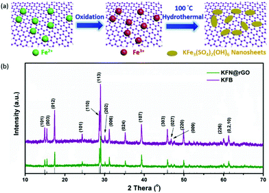 | ||
| Fig. 1 (a) Schematic illustration of the preparation process of KFN@rGO and (b) XRD patterns of as-prepared KFN@rGO and its bulk counterpart. | ||
The detailed morphologies and structures were characterized by SEM and TEM. As shown in Fig. S1,† the bulk KFB exhibits an irregular flake-like morphology with about 0.5–5 μm length and 200–300 nm thickness. The panoramic SEM image (Fig. 2a) exhibits the typical hybrid composite structures of rGO and KFe3(SO4)2(OH)6. Fig. 2b and c depict the morphology of KFe3(SO4)2(OH)6 nanosheet@rGO. Due to the induction of Fe3+ ions which are bound by the functional group of GO, KFe3(SO4)2(OH)6 nanosheets grow thickly on the surface of the GO sheet. In the magnified SEM image (Fig. 2c), the ultrathin nanosheets can be clearly observed with only about 10 nm thickness. EDS mapping was further carried out to characterize the elemental composition and distribution of the as-prepared KFN@rGO. As shown in Fig. 2d1–d4, the K, Fe, S and O elements are distributed homogeneously in the selected area (red box marked in Fig. 2b), indicating the high uniformity of ultrathin KFe3(SO4)2(OH)6 nanosheets. Besides, the results of ICP-AES (Table S1†) further demonstrate that the molar ratio of K![[thin space (1/6-em)]](https://www.rsc.org/images/entities/char_2009.gif) :
:![[thin space (1/6-em)]](https://www.rsc.org/images/entities/char_2009.gif) Fe is 1
Fe is 1![[thin space (1/6-em)]](https://www.rsc.org/images/entities/char_2009.gif) :
:![[thin space (1/6-em)]](https://www.rsc.org/images/entities/char_2009.gif) 3, corresponding to the ideal chemical formula. The TEM image of KFN@rGO (Fig. 2e) exhibits the typical hybrid structure of rGO and crystal nanosheets. The ultrathin nanosheets with the diameter range from 20 to 200 nm are scattered on the rGO sheets (red areas highlighted in Fig. 2e). The HRTEM image selected from the biggest red area in the inset of Fig. 2f displays the clear lattice fringes with an interplanar distance of about 0.36 nm, which is assigned to the (110) facet of jarosite rhombohedral KFe3(SO4)2(OH)6. The superiorities of the ultrathin nanosheet structure and the flexible and conductive rGO substrate would endow the KFN@rGO hybrid composite with the ability to buffer the volume expansion and increase the electronic conductivity simultaneously.
3, corresponding to the ideal chemical formula. The TEM image of KFN@rGO (Fig. 2e) exhibits the typical hybrid structure of rGO and crystal nanosheets. The ultrathin nanosheets with the diameter range from 20 to 200 nm are scattered on the rGO sheets (red areas highlighted in Fig. 2e). The HRTEM image selected from the biggest red area in the inset of Fig. 2f displays the clear lattice fringes with an interplanar distance of about 0.36 nm, which is assigned to the (110) facet of jarosite rhombohedral KFe3(SO4)2(OH)6. The superiorities of the ultrathin nanosheet structure and the flexible and conductive rGO substrate would endow the KFN@rGO hybrid composite with the ability to buffer the volume expansion and increase the electronic conductivity simultaneously.
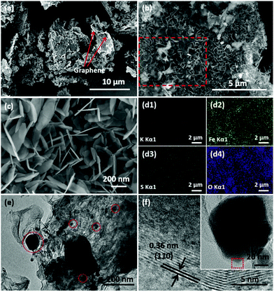 | ||
| Fig. 2 (a–c) SEM images of KFN@rGO at different magnifications; (d) EDS elemental mapping images of KFN@rGO; (e and f) TEM and HRTEM images of KFN@rGO. | ||
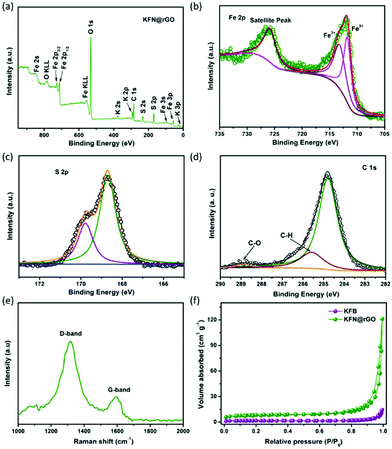
The survey scan XPS spectrum exhibits the presence of K 3p, K 2p, K 2s, Fe 3p, Fe 3s, Fe 2p1/2, Fe 2p3/2, Fe 2s, S 2p, S 2s, C 1s and O 1s, with no evidence of impurities. The high resolution XPS spectra of KFN@rGO Fe 2p and S 2p are depicted in Fig. 3b and c, respectively. Fig. 3b confirms that Fe in KFN@rGO only exists in the form of ferric ions and without the Fe–O bond, as proved by the characteristic peaks at 713.3 and 711.8 eV.41 The S 2p peaks located at 168.7 and 169.8 eV demonstrate that the S element is only present in the S–O bond in the KFN@rGO hybrid composite.16 As shown in Fig. 3d, the high resolution C 1s spectrum exhibits three peaks located at 284.7, 285.6 and 288.7 eV. The presence of C–O and C–H bonds indicates the low reduction degree of graphene oxide.42 Furthermore, the presence of rGO and the graphitic quality of KFN@rGO were also evaluated by Raman spectroscopy. As shown in Fig. 3e, two typical D and G bands corresponding to the sp3-type disordered carbon and sp2-type ordered graphitic carbon were located at about 1334 and 1589 cm−1, respectively. The large ratio of ID and IG suggests the abundant defects and the disordered structure in rGO,43 which would induce a more pseudocapacitive effect in KFN@rGO cells. N2 isothermal adsorption/desorption measurements are depicted in Fig. 3f. The BET surface area of KFN@rGO (26.6 m2 g−1) is much higher than that of KFB (5.1 m2 g−1). Thermal stability is one of the critical issues for electrode materials. As shown in Fig. S2,† the KFN@rGO hybrid composite exhibits an obvious mass loss at about 390 and 600 °C, revealing the unexpected thermal stability. The thermal decomposition processes of KFN@rGO in air were further determined by XRD (inset of Fig. S2†). After annealing at 800 °C, the final pyrolysis products of KFN@rGO are mainly Fe2O3 and K2SO4. Based on these structural features, improved electrochemical performances of jarosite KFe3(SO4)2(OH)6 would be expected.
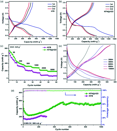
CR2032 cells were used to evaluate the electrochemical performances of the as-prepared anode KFB and KFN@rGO. The typical charge–discharge curves of KFB and KFN@rGO in the voltage range of 0.005–3.0 V at 20 mA g−1 are depicted in Fig. 4a and b, respectively. The KFN@rGO electrode exhibits an obvious discharge plateau at about 0.9 V and more reversibility at the 2nd and 3rd cycle than its counterpart. The initial discharge and charge capacity of KFN@rGO is 1550 and 913 mA h g−1, respectively, which is much higher than that of KFB (1281 and 695 mA h g−1). The low initial coulombic efficiency can be ascribed to the formation of irreversible discharge products, i.e., Li2O, LiKSO4, LiOH, etc.16 In the first lithiation process, the reaction of KFe3(SO4)2(OH)6 and Li+ is irreversible. The products after this reaction are Fe, Li2S, Li2O, LiKSO4 and LiOH.16 As shown in Fig. S3,† the disappearance of the cathodic peak around 2.1 V in the 2nd and 3rd cycle indicates the irreversible lithiation process in the first cycle. At the subsequent charge process, the reversible reactions are the re-oxidation of Fe with the Li sources (such as Li2O and LiOH). Thus, the active materials in the cycles would be considered as Fe2O3 and FeOOH.
As shown in Fig. 4c, the rate properties of KFN@rGO under different current densities deliver more stable reversible discharge capacities (736, 443, 335, 299, 228 and 194 mA h g−1, respectively) than those of the KFB electrode. The cycling tests were operated under a current density of 500 mA g−1, and the result is depicted in Fig. 4d. The KFN@rGO electrode delivers noticeable capacity fading in the first 80 cycles. This common phenomenon is mainly due to the slow Li+ diffusion and high charge–discharge resistance. Impressively, the discharge capacity of KFN@rGO gradually increased and stabilized at 545 mA h g−1 at the end of 1000 cycles. The close to 100% coulombic efficiency (Fig. 4d) and the detailed charge–discharge curves at different cycles (Fig. 4e) further demonstrate the high reversibility of the KFN@rGO electrode during the cycles. As the counterpart, the KFB only delivers 206 mA h g−1 at the 300th cycle under the same test conditions. Moreover, the evaluations of the cycling stability of KFN@rGO at different current densities are depicted in Fig. S4.† The KFN@rGO electrode delivers a reversible capacity of 486.6 and 356.9 mA h g−1 after 300 cycles under 100 and 1000 mA g−1, respectively. Notably, all the cycling curves of KFN@rGO and KFB exhibit the same tendency of first decreasing and then increasing. These results would imply that the phenomenon of capacity increasing is a common characteristic for the KFe3(SO4)2(OH)6 anode. The increasing capacity could be attributed to three aspects: (i) the decreased resistance of charge transfer and enhanced Li+ dynamics after the initial activation process are beneficial for lithium storage performance. (ii) The effects of volume expansion can reduce the particle size, which also facilitates lithium storage.44–46 (iii) After the activation process, the formation of more active sites would promote more interfacial lithium storage, leading to an increase in capacity.37,47 In comparison with KFB, the improved cycling and rate performances would be attributed to the ultrathin KFe3(SO4)2(OH)6 nanosheets and the flexible graphene sheets, which suppressed the volume expansion and enhanced the conductivity during the electrochemical evaluations.
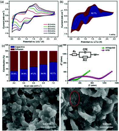
CV curves at different scanning rates were measured to further explain the potential reasons for the unexpected cycling performance of the KFN@rGO electrode. The CV curves at different scanning rates from 0.2 to 1.0 mV s−1 are shown in Fig. 5a. After the activated processes, all the curves display a similar peak shape and a gradually broadened area with increasing scanning rate. The cathodic peak around 1.2 V corresponds to the reactions of FeOOH + Li+ + e− → FeOOHLi and Fe2O3 + 6Li+ + 6e− → 2Fe + 3Li2O.48,49 The peak at 0.65 V is attributed to the reaction of FeOOHLi + 2Li+ + 2e− → Fe + LiOH + Li2O.50 Moreover, the subsequent anodic peak from 1.5 V to 1.75 V represents the oxidation from Fe0 to Fe3+, such as the reversible reaction of 2Fe + 3Li2O → Fe2O3 + 6Li+ + 6e− and Fe + LiOH + Li2O → FeOOH + 3Li+ + 3e−.51 The total charge storage (reflected by the area under the CV curves) can be attributed to the surface induced capacitive process and the diffusion controlled insertion process.52 The contribution ratio of the capacitive effect on the total lithium storage can be calculated according to eqn (1):53,54
| i(V) = k1v + k2v0.5 | (1) |
In this equation, the area of i(V), k1v and k2v0.5 corresponded to the total charge storage, surface induced capacitive process and diffusion controlled insertion process, respectively.55,56 The relationship between i(V)/v0.5 and v0.5 at different potentials during the CV process from 0.2 to 1.0 mV s−1 has been used to fit k1 (the slope of the fitting line). According to the values of k1 at different potentials, the potential profile for the current from the capacitive effects (blue region) at 1 mV s−1 is depicted in Fig. 5b (the detailed values to calculate the slopes are listed in Tables S2 and S3†). The capacitive contribution of KFN@rGO is about 62.7%. As shown in Fig. 5c, the pseudocapacitive contribution was enhanced moderately with increasing scanning rate. The ratios at 0.2, 0.4, 0.6 and 0.8 mV s−1 are 33.6%, 39.9%, 47.2% and 54.9%, respectively. This result proves that the hybrid structure of ultrathin KFe3(SO4)2(OH)6 nanosheets and rGO sheets could enhance the pseudocapacitive charge storage performance, thus resulting in durable lithium storage properties.
EIS measurements (100k Hz to 0.01 Hz with an AC amplitude of 5 mV) were further used to investigate the advantages of the KFN@rGO electrode. As shown in Fig. 5d, both the Nyquist plots display the downward semicircle in the high–middle frequency and an oblique line in the low frequency region. The equivalent circuit model used to fit the value of the components is also presented in Fig. 5d. According to the calculated results, the value of Rct corresponding to the charge transfer resistance is 236.5 Ω in the KFN@rGO cell, which is much smaller than that of KFB (1015 Ω). Smaller Rct means the reduction of unsatisfactory side reactions on the electrode/electrolyte interface.57–59 In addition, the Nyquist plots of KFN@rGO after the activated process (three cycles under a low current density) display a higher resistance than the cycled cell, which indicated the decreased resistance of charge transfer and enhanced Li+ dynamics after the initial activation process (Fig. S5†). Furthermore, two kinds of cells after 300 cycles have been dissected to analyze the correlation between the cycling performance and structural stability. As shown in Fig. 5e, the KFB bulk flakes have been broken into irregular particles due to the volumetric expansion during the cycles. In contrast, the KFN@rGO electrode exhibits a typical flake-like structure and bare ultrathin nanosheets in the region marked by the red ellipse, which indicated that the hybrid structure of ultrathin nanosheets and rGO may tolerate the stress from the volumetric expansion. XRD patterns of the cycled electrodes are depicted in Fig. S6.† KFN@rGO exhibits better crystallization than its counterpart, indicating better structural reversibility. The diffraction peaks of KFN@rGO can be indexed to Fe2O3, FeOOH and Cu, respectively. Considering that the cells were dissected at the charged state, this result is consistent with the CV analysis results. The EDS spectrum of the cycled KFN@rGO electrode (Fig. S7†) proves that the atomic ratio of K![[thin space (1/6-em)]](https://www.rsc.org/images/entities/char_2009.gif) :
:![[thin space (1/6-em)]](https://www.rsc.org/images/entities/char_2009.gif) Fe
Fe![[thin space (1/6-em)]](https://www.rsc.org/images/entities/char_2009.gif) :
:![[thin space (1/6-em)]](https://www.rsc.org/images/entities/char_2009.gif) S is about 1
S is about 1![[thin space (1/6-em)]](https://www.rsc.org/images/entities/char_2009.gif) :
:![[thin space (1/6-em)]](https://www.rsc.org/images/entities/char_2009.gif) 3
3![[thin space (1/6-em)]](https://www.rsc.org/images/entities/char_2009.gif) :
:![[thin space (1/6-em)]](https://www.rsc.org/images/entities/char_2009.gif) 2, further demonstrating its structural stability.
2, further demonstrating its structural stability.
Conclusions
In summary, jarosite ultrathin KFe3(SO4)2(OH)6 nanosheets with an rGO substrate were synthesized by using a facile and scalable route. The structural features (ultrathin nanosheets and rGO flexible substrate) endow the KFN@rGO with an improved capability of tolerance to volume change and electronic conductivity. Moreover, this hybrid structure enhanced the gradually increasing pseudocapacitive effect (62.7% at 1 mV s−1). Owing to the above superiorities, the as-prepared KFN@rGO delivered robust lithium storage performances: high reversible capacity (913 mA h g−1 at 20 mA g−1) and robust cycling stability (545 mA h g−1 at the end of 1000 cycles at 500 mA g−1). This work would provide an effective route to improve the electrochemical performances of other jarosite minerals through the induced pseudocapacitive effect.Conflicts of interest
There are no conflicts to declare.Acknowledgements
This work was financially supported by the National Natural Science Foundation of China (No. 21705072), the Colleges and Universities in Henan Province Key Science and Research Project (No. 18A430002 and 17A150039), the Program for Innovation Talents (in Science and Technology) in University of Henan Province (Grant No. 16HASTIT044), the Henan Province Science and Technology Tackle Key Problems Project (No. 172102310477 and 182102310908), and the Sichuan Province Science and Technology Support Program (No. 2017GZ0132).Notes and references
- A. Konarov, S. Myung and Y. Sun, ACS Energy Lett., 2017, 2, 703–708 CrossRef CAS.
- Y. Liang, H. Tian, J. Repac, S. Liou, J. Chen, W. Han, C. Wang and S. Ehrman, Energy Storage Mater., 2018, 13, 8–18 CrossRef.
- R. Chen, R. Luo, Y. Huang, F. Wu and L. Li, Adv. Sci., 2016, 3, 1600051 CrossRef PubMed.
- W. Guo, W. Sun, L. Lv, S. Kong and Y. Wang, ACS Nano, 2017, 11, 4198–4205 CrossRef CAS PubMed.
- Y. Dong, B. Wang, K. Zhao, Y. Yu, X. Wang, L. Mai and S. Jin, Nano Lett., 2017, 17, 5740–5746 CrossRef CAS PubMed.
- M. Shi, T. Wu, X. Song, J. Liu, L. Zhao, P. Zhang and L. Gao, J. Mater. Chem. A, 2016, 4, 10666–10672 RSC.
- Y. Zhang, P. Chen, X. Gao, B. Wang, H. Liu, H. Wu, H. Liu and S. Dou, Adv. Funct. Mater., 2016, 26, 7754–7765 CrossRef CAS.
- C. Liao, Q. Zhang, T. Zhai, H. Li and H. Zhou, Energy Storage Mater., 2017, 7, 17–31 CrossRef.
- N. Wu, W. Du, G. Liu, Z. Zhou, H. Fu, Q. Tang, X. Liu and Y. He, ACS Appl. Mater. Interfaces, 2017, 9, 43681–43687 CrossRef CAS PubMed.
- P. Liu, K. Zhu, Y. Gao, H. Luo and L. Lu, Adv. Energy Mater., 2017, 7, 1700547 CrossRef.
- Z. Xu, X. Liu, Y. Luo, L. Zhou and J. Kim, Prog. Mater. Sci., 2017, 90, 1–44 CrossRef CAS.
- W. Li, S. Hu, X. Luo, Z. Li, X. Sun, M. Li, F. Liu and Y. Yu, Adv. Mater., 2017, 29, 1605820 CrossRef PubMed.
- J. Pang, A. Bachmatiuk, Y. Yin, B. Trzebicka, L. Zhao, L. Fu, R. G. Mendes, T. Gemming, Z. Liu and M. H. Rummeli, Adv. Energy Mater., 2018, 8, 1702093 CrossRef.
- M. Gnanavel, V. Pralong, O. I. Lebedev, V. Caignaert, P. Bazin and B. Raveau, Chem. Mater., 2014, 26, 4521–4527 CrossRef CAS.
- T. Fujita, H. Yamaguchi, S. Kimura, T. Kashiwagi, M. Hagiwara, K. Matan, D. Grohol, D. G. Nocera and Y. S. Lee, Phys. Rev. B: Condens. Matter Mater. Phys., 2012, 85, 94409 CrossRef.
- Y. Ding, Y. Wen, C. Chen, P. A. van Aken, J. Maier and Y. Yu, ACS Appl. Mater. Interfaces, 2015, 7, 10518–10524 CrossRef CAS PubMed.
- A. M. L. Smith, K. A. Hudson-Edwards, W. E. Dubbin and K. Wright, Geochim. Cosmochim. Acta, 2006, 70, 608–621 CrossRef CAS.
- W. Xu, Z. Xie, X. Cui, K. Zhao, L. Zhang, L. Mai and Y. Wang, J. Mater. Chem. A, 2016, 4, 3735–3742 RSC.
- T. Sheng, Y. F. Xu, Y. X. Jiang, L. Huang, N. Tian, Z. Y. Zhou, I. Broadwell and S. Sun, Acc. Chem. Res., 2016, 49, 2569–2577 CrossRef CAS PubMed.
- L. Cong, H. Xie and J. Li, Adv. Energy Mater., 2017, 7, 1601906 CrossRef.
- N. Wu, Y. Zhang, Y. Wei, H. Liu and H. Wu, ACS Appl. Mater. Interfaces, 2016, 8, 25361–25368 CrossRef CAS PubMed.
- F. Wang, Z. Wang, T. A. Shifa, Y. Wen, F. Wang, X. Zhan, Q. Wang, K. Xu, Y. Huang, L. Yin, C. Jiang and J. He, Adv. Funct. Mater., 2017, 27, 1603254 CrossRef.
- W. Bao, L. Liu, C. Wang, S. Choi, D. Wang and G. Wang, Adv. Energy Mater., 2018, 8, 1702485 CrossRef.
- X. Zhang, L. Hou, A. Ciesielski and P. Samorì, Adv. Energy Mater., 2016, 6, 1600671 CrossRef.
- Q. Xu, J. Li, J. Sun, Y. Yin, L. Wan and Y. Guo, Adv. Energy Mater., 2017, 7, 1601481 CrossRef.
- H. Zhang, X. Huang, O. Noonan, L. Zhou and C. Yu, Adv. Funct. Mater., 2017, 27, 1606023 CrossRef.
- H. Hou, L. Shao, Y. Zhang, G. Zou, J. Chen and X. Ji, Adv. Sci., 2017, 4, 1600243 CrossRef PubMed.
- H. Hou, C. E. Banks, M. Jing, Y. Zhang and X. Ji, Adv. Mater., 2015, 27, 7861–7866 CrossRef CAS PubMed.
- X. Deng, Z. Wei, C. Cui, Q. Liu, C. Wang and J. Ma, J. Mater. Chem. A, 2018, 6, 4013–4022 RSC.
- L. Zhang, K. Zhao, Y. Luo, Y. Dong, W. Xu, M. Yan, W. Ren, L. Zhou, L. Qu and L. Mai, ACS Appl. Mater. Interfaces, 2016, 8, 7139–7146 CrossRef CAS PubMed.
- H. Wang, X. Zhao, K. Yin, Y. Li, L. Chen, X. Yang, W. Zhang, B. Su and G. Cao, ACS Appl. Mater. Interfaces, 2017, 9, 43665–43673 CrossRef CAS PubMed.
- P. Ge, H. Hou, S. Li, L. Yang and X. Ji, Adv. Funct. Mater., 2018, 28, 1801765 CrossRef.
- D. Chao, C. Zhu, P. Yang, X. Xia, J. Liu, J. Wang, X. Fan, S. V. Savilov, J. Lin, H. J. Fan and Z. X. Shen, Nat. Commun., 2016, 7, 12122 CrossRef CAS PubMed.
- C. Wang, Y. Zhao, X. Zhao, X. Zhai, C. Ding, J. Li and H. Jin, Electrochim. Acta, 2018, 282, 955–963 CrossRef CAS.
- C. Liao and S. Wu, Chem. Eng. J., 2019, 355, 805–814 CrossRef CAS.
- Y. Tang, L. Liu, H. Zhao, Y. Zhang, L. B. Kong, S. Gao, X. Li, L. Wang and D. Jia, ACS Appl. Mater. Interfaces, 2018, 10, 20225–20230 CrossRef CAS PubMed.
- N. Wu, W. Du, X. Gao, L. Zhao, G. Liu, X. Liu, H. Wu and Y. He, Nanoscale, 2018, 10, 11460–11466 RSC.
- Y. Ding, Y. Wen, P. A. van Aken, J. Maier and Y. Yu, Chem. Mater., 2015, 27, 3143–3149 CrossRef CAS.
- R. Zhao, Y. Li and C. K. Chan, J. Phys. Chem. C, 2016, 120, 9702–9712 CrossRef CAS.
- N. Wu, Y. Zhang, Y. Guo, S. Liu, H. Liu and H. Wu, ACS Appl. Mater. Interfaces, 2016, 8, 2723–2731 CrossRef CAS PubMed.
- W. Han and M. Gao, Cryst. Growth Des., 2008, 8, 1023–1030 CrossRef CAS.
- Q. Wang, B. Wang, Z. Zhang, Y. Zhang, J. Peng, Y. Zhang and H. Wu, Inorg. Chem. Front., 2018, 5, 2605–2614 RSC.
- Y. Zhang, P. Chen, X. Gao, B. Wang, H. Liu, H. Wu, H. Liu and S. Dou, Adv. Funct. Mater., 2016, 26, 7754–7765 CrossRef CAS.
- M. F. Hassan, Z. Guo, Z. Chen and H. Liu, Mater. Res. Bull., 2011, 46, 858–864 CrossRef CAS.
- Y. Sun, X. Hu, W. Luo, F. Xia and Y. Huang, Adv. Funct. Mater., 2013, 23, 2436–2444 CrossRef CAS.
- Z. Xiaosi, J. W. Li and Y. G. Guo, Adv. Mater., 2013, 25, 2152–2157 CrossRef PubMed.
- J. Maier, Angew. Chem., Int. Ed., 2013, 52, 4998–5026 CrossRef CAS PubMed.
- T. Tabuchi, Y. Katayama, T. Nukuda and Z. Ogumi, J. Power Sources, 2009, 191, 636–639 CrossRef CAS.
- J. S. Cho, Y. J. Hong and Y. C. Kang, ACS Nano, 2015, 9, 4026–4035 CrossRef CAS PubMed.
- M. Zou, W. Wen, J. Li, Y. Lin, H. Lai and Z. Huang, J. Energy Chem., 2014, 23, 513–518 CrossRef.
- H. Liu, G. Wang, J. Park, J. Wang, H. Liu and C. Zhang, Electrochim. Acta, 2009, 54, 1733–1736 CrossRef CAS.
- D. Chao, P. Liang, Z. Chen, L. Bai, H. Shen, X. Liu, X. Xia, Y. Zhao, S. V. Savilov, J. Lin and Z. X. Shen, ACS Nano, 2016, 10, 10211–10219 CrossRef CAS PubMed.
- D. Liu, D. Liu, B. Hou, Y. Wang, J. Guo, Q. Ning and X. Wu, Electrochim. Acta, 2018, 264, 292–300 CrossRef CAS.
- X. Yu, C. Pei, W. Chen and L. Feng, Electrochim. Acta, 2018, 272, 119–126 CrossRef CAS.
- Q. Wei, Q. Wang, Q. Li, Q. An, Y. Zhao, Z. Peng, Y. Jiang, S. Tan, M. Yan and L. Mai, Nano Energy, 2018, 47, 294–300 CrossRef CAS.
- P. Ge, C. Zhang, H. Hou, B. Wu, L. Zhou, S. Li, T. Wu, J. Hu, L. Mai and X. Ji, Nano Energy, 2018, 48, 617–629 CrossRef CAS.
- N. Wu, Y. Zhang, Y. Wei, H. Liu and H. Wu, ACS Appl. Mater. Interfaces, 2016, 8, 25361–25368 CrossRef CAS PubMed.
- N. Wu, H. Wu, J. Kim, X. Liu and Y. Zhang, ChemElectroChem, 2018, 5, 78–83 CrossRef CAS.
- X. Wang, L. Zhang, C. Zhang and P. Wu, Inorg. Chem. Front., 2017, 4, 889–897 RSC.
Footnote |
| † Electronic supplementary information (ESI) available. See DOI: 10.1039/c8qi01165f |
| This journal is © the Partner Organisations 2019 |

