 Open Access Article
Experimental study on viscosity reduction of heavy oil by hydrogen donors using a cavitating jet
Chunhao Wan ,
Ruihe Wang*,
Weidong Zhou* and
Luopeng Li
College of Petroleum Engineering, China University of Petroleum (East China), Qingdao, 266580, China. E-mail: wanchunhao@126.com
First published on 21st January 2019
Abstract
Cavitating jet technology is used to change the quality and to reduce the viscosity of heavy oil because bubble collapse can cause extreme conditions such as high pressure and temperature. The experimental study on the viscosity reduction of heavy oil using a cavitating jet was performed through a self-designed experimental system for heavy oil viscosity reduction by a cavitating jet. Tetrahydronaphthalene was used as the hydrogen donor, and after adding different amount of tetrahydronaphthalene, the viscosity change of the heavy oil was studied before and after treatment by the cavitation jet. The experimental results show that cavitating jet technology can be used to improve the quality and reduce the viscosity of heavy oil, and the addition of tetrahydronaphthalene can effectively reduce the viscosity of heavy oil. With the increase in the amount of tetrahydronaphthalene added, the viscosity reduction effect on the heavy oil improved, and the viscosity reduction rate increased. When a certain amount of tetrahydronaphthalene was added, the viscosity of the heavy oil decreased gradually and plateaued with the increase in the cycles of cavitation jet treatment. The addition of tetrahydronaphthalene can dilute the heavy oil and effectively reduce the viscosity and improve the quality of heavy oil by providing active hydrogen to close the macromolecular hydrocarbon free radicals generated by the cavitation effect.
1. Introduction
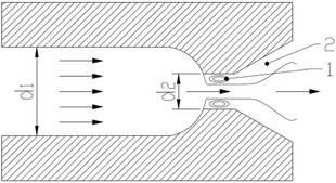
Heavy oil has high viscosity and poor fluidity since it comprises numerous macromolecular substances, which severely restricts the production, transportation and processing of heavy oil. Thus, strategies to reduce the viscosity and improve the quality of heavy oil are of great importance to its utilization.1,2 At present, the commonly used methods for heavy oil viscosity reduction include heating, mixing thin oil and adding a viscosity reducer. However, these methods exhibit problems such as high energy consumption, low source of thin oil and high cost.3–6 The use of ultrasonic cavitation to treat the super heavy oil can reduce the viscosity of heavy oil effectively. However, the processing capacity and treatment efficiency of ultrasonic cavitation is low.7 Cavitating jet technology has the characteristics of simple structure and easy implementation. It is of certain application value and economic benefit to use cavitating jet technology to treat heavy oil to reduce its viscosity. Under the extreme environmental conditions produced by the cavitation effect, the macromolecule structures in heavy oil are prone to fracture and form free radicals. When the macromolecular free radicals condense, the macromolecule structure of heavy oil will enlarge or even undergo coking, which are not conducive to the visbreaking treatment of heavy oil. The viscosity can be effectively reduced and the quality of heavy oil can be improved by adding moderate amounts of hydrogen donors into the heavy oil system and inhibiting the condensation reaction of free radicals.Cavitating jet is a form of a jet where cavitation bubbles are induced in the nozzle so that many cavitation bubbles are formed in the effluent fluid and the energy produced by the cavitation bubble collapse is used to enhance the jet effect. The mechanism is shown in Fig. 1.
As shown in the cavitation nozzle in Fig. 1, jet flow will be formed at the exit position of nozzle due to the smaller aperture when the liquid flow enters the nozzle at a certain speed and exits the nozzle. There are two low pressure areas formed before and after the formation of a jet: one is the tangential region when a jet flow is formed (i.e., the shear zone shown in 1); the other is the eddy region formed when the jet flow enters a relatively static fluid (i.e., the shear zone shown in 2). The pressure in these two areas is lower than the necessary pressure for the stability of gas cores (i.e., the saturated vapor pressure of the fluid at this temperature) and the gas cores in the fluid grow and rapidly form large vapor-filled cavitation bubbles. When cavitation bubbles flow out of this area with the fluid, the bubbles collapse, resulting in energy release due to the sudden increase in pressure. This creates the cavitation effect.8,9
The collapse of cavitation bubbles can produce extreme conditions of instantaneous high temperature and high pressure, and can form strong shock waves and micro-jet flows.10–12 Suslick concluded that when the cavitation bubbles collapse, the hot spot temperature in the bubble is about 5200 K and the temperature on the bubble wall is about 1900 K. The pressure in the bubble is more than 50 MPa.13 Hammit concluded that the velocity of the micro-jet near the wall could reach 70–180 m s−1 and the surge pressure on the surface of object could be as high as 140–170 MPa when the floating bubbles collapse. However, the impact pulse duration lasts only a few microseconds at a time.14 The macromolecule in the heavy oil will undergo cracking and other reactions, such that the physical properties of heavy oil change in such an extreme environment. Professor Deng Songsheng pointed out that when the water contains macromolecular organic matter, the high temperature and high pressure caused by cavitation bubble collapse would have an effect on the organic matter, resulting in cleavage of chains in the macromolecule and subsequent degradation. At the same time, the strong oxides and free radicals produced by cavitation bubble collapse in water would react with the macromolecular organic matter; thus, many organic compounds, which are difficult to degrade under normal conditions, are degraded.15 The popular use of a cavitating jet to treat wastewater containing organic matter indicates that cavitating jet technology has certain effects on the degradation of organic matters.16,17
Tetrahydronaphthalene (THN) was chosen as the hydrogen donor in this study, and the heavy oil with varying amounts of THN was disposed by a cavitating jet through the self-designed experimental system for heavy oil viscosity reduction by a cavitating jet. The mechanism of the hydrogen donor effect on the cavitating jet to reduce the viscosity of the heavy oil was explored by analyzing the viscosity change of heavy oil before and after treatment by the cavitating jet. The analysis of this mechanism can provide a theoretical basis for the technology of cavitating jet to reduce the viscosity of heavy oil.
2. Experimental
2.1 Experimental material
(1) The viscosity of heavy oil (50 °C) used in the experiment was 355 mPa s.(2) Hydrogen donor
Generally, the substances that are able to provide active hydrogen free radicals for heavy oil hydro-upgrading can be used as hydrogen donors. For example, water, hydrogen in inorganic matter18 and methane, formic acid, cycloalkyl aromatic compounds (such as tetrahydronaphthalene, decahydronaphthalene, and dihydroanthracene) in organic matter19,20 can be used as donors. In addition, some petrochemical products or by-products (such as the coking fraction oil, cycloalkyl straight-run diesel oil and clarified oil)21,22 that are rich in polycyclic aromatic compounds are used as industrial hydrogen donors because of their low cost and easy accessibility.
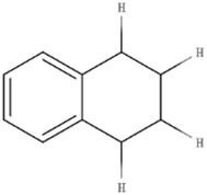
THN is a type of hydrogen donor commonly used in experimental research and has a good hydrogen supply effect.23,24 Therefore, THN was selected as the hydrogen donor for research in this study. Its molecular structure is shown in Fig. 2.
The molecular structure of THN is composed of a naphthenic ring and a benzene ring. The two hydrogen atoms in the naphthenic ring adjacent to the benzene ring (α-hydrogen atoms) become very active under the influence of the benzene ring π-bond. THN can produce reactive hydrogen free radicals and transform into naphthalene under certain conditions. The reaction equation is shown in Fig. 3.
2.2 Experimental system
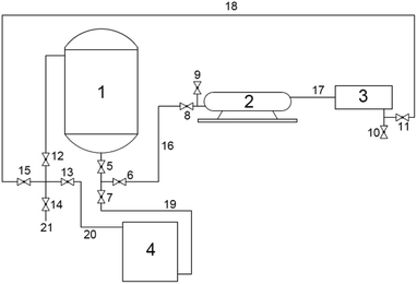
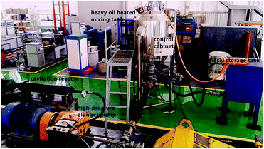
According to the requirements of these experiments, the experimental system for heavy oil viscosity reduction of a cavitating jet was independently designed and manufactured by the high pressure water jet research center of China University of Petroleum (East China). The experimental system is mainly composed of the heavy oil-heated mixing tank, the high-pressure plunger pump, the cavitation reactor (including a cavitation nozzle), the diesel storage tank, valves and high pressure lines. The devices are connected to each other through high pressure lines and valves. The whole system is divided into heavy oil viscosity reduction treatment system and diesel cleaning system by the valve switches. The connection diagram of the experimental system and the physical diagram are shown in Fig. 4 and 5, respectively.The experimental system can realize the function of heating and storing heavy oil, mixing and stirring heavy oil with hydrogen donor, cavitating jet treatment of heavy oil and sampling.
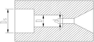
The cavitation nozzle is the site of the cavitating jet and the key structure of the whole experimental system. Selecting the appropriate cavitation nozzle is very important for the generation of a cavitating jet and its effect on the viscosity reduction of heavy oil. The types of commonly used cavitation nozzles mainly include rotary vane cavitation nozzles, central body cavitation nozzles, self-excited oscillating nozzles and angular cavitation nozzles.25–28 The organ pipe cavitation nozzle with a diffusion section was designed in the experiment according to the characteristics of each cavitation nozzle and the experimental conditions. The structure of organ pipe cavitation nozzle is shown in Fig. 6.
The displacement of the high-pressure plunger pump was kept unchanged during the experiment and the pressure drop of the nozzle was determined by the structure of the cavitation nozzle. The displacement of the high-pressure plunger pump and the pressure drop of the nozzle were measured by experiments in the early stage, as shown in Table 1.
| Nozzle | Diameter | Rate of flow | Flow coefficient | Pressure drop |
|---|---|---|---|---|
| Organ pipe cavitation nozzle | 2.76 mm | 75 L min−1 | 0.74 | 40 MPa |
The internal and external flow field of the organ pipe cavitation nozzle was numerically simulated using the mixture model, RNG k-epsilon turbulence model and Z-G-B cavitation model of the Fluent software. The nozzle structure and boundary conditions are shown in Table 1. The gas volume fraction distribution cloud diagram of heavy oil in the cavitation nozzle were obtained and shown in Fig. 7.
It can be seen from the gas volume fraction distribution cloud diagram that heavy oil can produce good a cavitation jet under this condition, so that the designed organ pipe cavitation nozzle can meet the requirement of the experiment.
2.3 Experimental steps
The experimental operation steps are as follows:(1) The experimental equipment was connected, as shown in Fig. 4 and the experimental system was checked for leaks.
(2) After checking, all valves were closed and heat-conduction oil was added to the jacket of the heated mixing tank.
(3) The cavitation nozzle in the cavitation reactor was installed and the spray distance was adjusted to a certain distance.
(4) The displacement of high-pressure plunger pump measured according to the experiment was about 75 L min−1 300 L heavy oil material was added to the heated mixing tank through the oil inlet so that the heavy oil could be treated by the cavitating jet once every 4 minutes. The switch of heat pipe was turned on and the heating temperature of the heat-conduction oil and the heavy oil was maintained at 50 °C. The temperature of heat-conduction oil and heavy oil can be displayed on the control cabinet in real time through the temperature sensor. When the heavy oil was heated to 50 °C, the switch of the motor at the top of the heated mixing tank was turned on and the heavy oil was stirred for half an hour to keep the heavy oil stable.
(5) Valves 5, 6, 8, 11, 12, 15 were opened to form the cavitating jet heavy oil viscosity reduction treatment system and the high-pressure plunger pump was opened to treat the heavy oil. Then, valve 14 was opened and 1 L of sample was removed from the sampling tube at 0 time, 4th time, 12th time, 20th time, 32th time and 40th time.
(6) The heavy oil from the heated mixing tank and pipelines was removed. Then, 300 L heavy oil was added along with addition of 0.03 and 0.06 mass fraction of THN to the heated mixing tank and the experiment steps (4) and (5) were repeated.
(7) At the end of each experiment, all the valves were opened and all the heavy oil in the heated mixing tank and the whole experimental system was removed. The above steps were repeated until all the experiments were completed.
(8) After completing all the experiments, the cavitation nozzle was removed and all the valves were closed. Then, 300 L diesel was added to the diesel storage tank and valves 6, 7, 8, 11, 13, and 15 were opened to form the diesel cleaning system. Then, the high-pressure plunger pump was operated for half an hour to clean the heavy oil in the whole system.
(9) Finally, the viscosity of heavy oil samples was measured and the obtained data was processed.
3. Results and discussion
3.1 Analysis of experimental results
The heavy oil without tetrahydronaphthalene and with the added mass fractions of 3% and 6% tetrahydronaphthalene was treated by a cavitating jet using the heavy oil viscosity reduction experiment system under the experimental conditions. Samples were taken at 1st, 3rd, 5th, 8th and 10th time during the cavitating jet treatment. The viscosities of each set of samples at 50 °C were measured with a brinell rotating viscometer and the measured data was recorded and shown in Tables 2–4.| Treatment number | Viscosity/mPa s | % viscosity reduction | |
|---|---|---|---|
| Measuring values | Average values | ||
| 0 | 356 | 355 | 0 |
| 354 | |||
| 1 | 347 | 345 | 2.82 |
| 343 | |||
| 3 | 341 | 340 | 4.23 |
| 339 | |||
| 5 | 340 | 340 | 4.23 |
| 340 | |||
| 8 | 387 | 338 | 4.79 |
| 389 | |||
| 10 | 337 | 336 | 5.35 |
| 335 | |||
| Treatment number | Viscosity/mPa s | % viscosity reduction | |
|---|---|---|---|
| Measuring values | Average values | ||
| 0 | 274 | 272 | 0 |
| 270 | |||
| 1 | 263 | 264 | 2.94 |
| 265 | |||
| 3 | 255 | 254 | 6.62 |
| 253 | |||
| 5 | 253 | 252 | 7.35 |
| 251 | |||
| 8 | 249 | 248 | 8.82 |
| 247 | |||
| 10 | 240 | 242 | 11.03 |
| 244 | |||
| Treatment number | Viscosity/mPa s | % viscosity reduction | |
|---|---|---|---|
| Measuring values | Average values | ||
| 0 | 221 | 223 | 0 |
| 225 | |||
| 1 | 200 | 199 | 10.76 |
| 198 | |||
| 3 | 198 | 197 | 11.67 |
| 196 | |||
| 5 | 191 | 192 | 13.90 |
| 193 | |||
| 8 | 191 | 190 | 14.80 |
| 189 | |||
| 10 | 188 | 188 | 15.70 |
| 188 | |||
The addition of THN to heavy oil has a certain dilution effect on heavy oil because THN is a simple aromatic hydrocarbon and has small viscosity. As a result, the viscosity of heavy oil decreases after adding THN, and greater the volume of THN added, higher would be the decrease in heavy oil viscosity. Therefore, the viscosity of heavy oil after adding THN was taken as the benchmark viscosity when calculating the viscosity reduction rate. The ratio between the viscosity reduction of heavy oil after each cavitating jet treatment and the benchmark viscosity of heavy oil is expressed by the viscosity reduction rate of the hydrogen donor. The specific calculation formula is
 | (1) |
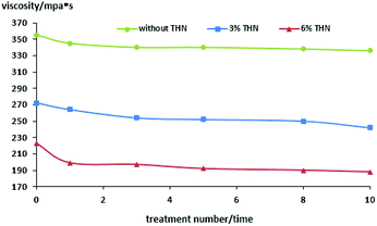
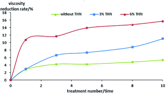
The relationship between viscosity reduction of heavy oil with the number of cavitating jet treatments is shown in Fig. 8 and 9.
As can be seen from Tables 2–4 and Fig. 8 and 9, the overall trend is that the viscosity of heavy oil decreases gradually with the increase in the cavitating jet treatment times. The viscosity reduction rate increases with the increase in the amount of THN added when the number of cavitating jet treatments is the same. When no THN is added, the viscosity of heavy oil decreases slightly with the increase in the cavitation jet treatment times, but the degree of reduction is not large, and the maximum viscosity reduction rate is only 5.35%. After adding THN with mass fractions of 0.03 and 0.06, the viscosity reduction rate of heavy oil increases to 11.03% and 15.7% after 10 time-cavitation jet treatment, except for the dilution effect of THN itself; moreover, the viscosity of heavy oil decreases to 242 mPa s and 188 mPa s after treatment, respectively. Compared with the viscosity of the heavy oil before treatment, the viscosity of the heavy oil has significantly decreased, and the viscosity of heavy oil is not regained after one week or more time. This indicates that the quality of the heavy oil has significantly improved, which can meet the requirement of transportation.
3.2 The action mechanism of hydrogen donor
The reason for the high viscosity of heavy oil is that it contains many macromolecular structures. The decrease in the viscosity of heavy oil when THN was and treated with cavitating jets indicates the change in the structures of the macromolecules in the heavy oil. This leads to reactions such as chain cleavage and depolymerization, such that the macromolecules in heavy oil convert to small molecules. One group of heavy oil before and after cavitating jet treatment was selected for component detection, and the results showed that the contents of saturates and aromatics increased and the contents of resins and asphaltenes decreased. This indicates that the macromolecules in the heavy oil crack so that the content of macromolecules reduces and the content of small molecules increases. Combined with the results of component detection, the effects of THN can usually be explained by the free radical reaction mechanism.29 The following general equations are used to explain the reaction mechanism where i, j, k, l, m and n are all integers.| CiH2i+2 → [CjH2j+1]˙+ [CkH2k+1]˙ | (2) |
① Hydrogen transfer reaction. The free radicals take hydrogen from other hydrocarbon molecules and form new free radicals, as shown in eqn (3).
| [CjH2j+1]˙ + ClH2l+2 → CjH2j+2 + [ClH2l+1]˙ | (3) |
② Radical decomposition. The free radicals break down to form new free radicals and olefins, as shown in eqn (4).
| [CmH2m+1]˙ → [Cm−nH2(m−n)+1]˙ + CnH2n | (4) |
③ Radical addition. The resulting olefins combine with the free radicals to form larger free radicals, as shown in eqn (5).
| CnH2n+[ClH2l+1]˙ → [Cn+lH2(n+l)+1]˙ | (5) |
④ Free radical isomerization. The position of atoms or atomic groups changes, as shown in eqn (6).
| [CmH2m+1]˙ → [CnH2n+2 − ĊH − Cm−n−1H2(m−n)−1] | (6) |
| [CjH2j+1]˙ + [CkH2k+1]˙ → CiH2i+2 | (7) |
It can be seen from eqn (2)–(7) that the macromolecular structure in heavy oil will break down the molecular chain and form active free radicals under the high temperature and pressure caused by the cavitation effect. The free radicals itself will also undergo splitting decomposition, addition and isomerism. When the amount of active hydrogen free radical in heavy oil is small, the resulting macromolecular free radical will undergo addition and combination to form a larger molecular structure, which is not conductive to viscosity reduction and heavy modification, as shown in eqn (5) and (7). The purpose of the hydrogen donor is to provide active hydrogen. The active hydrogen free radical produced under the cavitation effect can terminate the activity of the macromolecular free radical by combining with it, so as to prevent the growth of heavy oil macromolecules, promote the hydrogenation reaction, inhibit the condensation reaction, and improve the effect of heavy oil quality modification and viscosity reduction. Taking THN as an example, THN can release active hydrogen radicals under the condition of the cavitation effect. The active hydrogen radicals can combine with macromolecular radicals, and the reaction mechanism is shown in eqn (8)–(10). THN can effectively inhibit the condensation of macromolecular free radicals, achieving the goals of lowering the molecular weight, reducing the viscosity and improving the quality of heavy oil. THN itself becomes the aromatic compound after losing its hydrogen radical. As a result, the addition of THN can dilute the heavy oil to some extent and decrease the concentration of macromolecular radicals in the heavy oil so that the possibility of condensation of macromolecular free radicals is reduced. The generated active hydrogen free radicals can combine with macromolecular free radicals, effectively quenching the macromolecular free radicals, thus reducing the molecular weight of the heavy oil macromolecules and consequently reducing the viscosity and improving the quality of heavy oil.30,31
| R˙ + H–D–H → R–H + H–D˙ | (8) |
| R˙ + H–D˙ → R–H + aromatics | (9) |
| R˙ + H–D˙ → R–D–H | (10) |
4. Conclusions
(1) Cavitating jet technology is simple in structure and easy to implement. Cavitation bubble collapse can produce extremely high temperature and high pressure so that the macromolecular structure of the heavy oil can break under this condition and the viscosity of heavy oil can reduce.(2) The experimental results of heavy oil viscosity reduction performed in the self-designed experimental system indicate that when no THN is added, the viscosity of heavy oil decreases slightly with the increase in cavitating jet treatment times, but the degree of reduction is not large and the maximum viscosity reduction rate is only 5.35%. After adding THN with mass fraction of 0.03 and 0.06, the viscosity reduction rate of heavy oil increases to 11.03% and 15.7%, respectively. After 10 time-cavitation jet treatment, except for the dilution effect of THN itself, the viscosity of heavy oil decreases to 242 mPa s and 188 mPa s after treatment. Compared with the viscosity of the heavy oil before treatment, the viscosity of the heavy oil has significantly decreased.
(3) The addition of THN has an important function in viscosity reduction of heavy oil with cavitation jet treatment. In addition to the dilution effect, THN can generate the active hydrogen free radicals that can combine with the macromolecule free radicals under the cavitation effect to prevent the condensation of macromolecular free radicals and formation of larger molecular structures. Thus, it can effectively reduce the molecular weight, reduce the viscosity of heavy oil and improve the quality of heavy oil.
Conflicts of interest
There are no conflicts to declare.References
- K. Q. Meng, X. D. Tang, W. W. Zou and Y. X. Cui, Progress in research on heavy oil viscosity reduction technology, Natural Gas and Oil, 2009, 27(03), 30–34 Search PubMed.
- R. W. Liu, X. L. Chen and N. Zhou, Study on viscosity-reducing techniques and mechanisms for viscous crude oils, Adv. Fine Petrochem., 2008, 9, 20–25 CAS.
- W. C. Li, P. Liu, J. F. Yu and T. Yan, Feasibility analysis on electric heating of wellbore in heavy oilfield of Bohai, Fault-Block Oil Gas Field, 2012, 19, 513–516 Search PubMed.
- J. X. Guo and J. W. Zhang, Review on the technology of blending diluting oil in heavy oil well, Science Technology and Engineering, 2014, 14, 124–132 Search PubMed.
- F. Y. Zhang, J. B. Li, L. Zhu and G. Yang, Advance in oil-soluble viscosity reducers for viscous crude oil, Spec. Oil Gas Reservoirs, 2006, 13, 1–4 CAS.
- X. B. Li, M. L. Ge, J. Y. Chen, Y. F. Yi, F. C. Ding and G. Y. Zhang, Synthesis and evaluation of oil-soluble viscosity reducer for heavy oil, Science Technology and Engineering, 2016, 16, 177–180 Search PubMed.
- H. X. Xu, C. S. Pu, Q. L. Dong and M. J. Hu, Study on ultrasonic viscosity-reduction method of ultra-heavy oil, Science Technology and Engineering, 2012, 12, 5873–5876 Search PubMed.
- K. M. Kalumuck and G. L. Chahine, The use of cavitation jet to oxide organic compounds in water, J. Fluids Eng., 1998, 45, 245 Search PubMed.
- J. F. Guan, S. S. Deng, P. F. Zhang and W. X. Hua, Research progress of cavitation characteristics, Science Technology and Engineering, 2011, 11, 6674–6680 Search PubMed.
- J. Cai, X. L. Huai and X. F. Li, Investigation on cavitation bubble dynamics in compressible liquid under turbulence, Chin. Sci. Bull., 2010, 55, 857–866 CrossRef.
- J. Cai, X. L. Huai, R. S. Yan and X. F. Li, Dynamic analysis on temperature evolution inside a single bubble due to hydrodynamic cavitation under turbulence, Chin. Sci. Bull., 2011, 56, 947–955 CrossRef.
- Y. Q. Tao, J. Cai, B. Liu and X. L. Huai, Bubble dynamic analysis and hydroxyl radical production calculation at bubble collapse in turbulence flow, Journal of University of Chinese Academy of Sciences, 2017, 34, 191–197 Search PubMed.
- K. S. Suslick, Son chemistry, Science, 1990, 247, 1439–1445 CrossRef CAS PubMed.
- F. G. Hammit, Cavitation and multiphase flow phenomena, New York Mc Graw-Hill Book Co, New York, 1980 Search PubMed.
- S. S. Deng, F. D. Lei, Z. J. Li and Y. H. Shen, Analysis on physical and chemical effects of cavitating water jet flow, Environ. Prot., 2011, 29, 81–84 Search PubMed.
- Q. Ge, X. H. Li, Y. Y. Lu and Y. Kang, Mechanism of organic wastewater treatment by cavitating jets, J. Chongqing Univ., 2007, 30, 19–22 CAS.
- Q. Wei, M. L. Gao, S. X. Sun, S. Wang and J. M. Wu, Experimental study of decomposition of rhodamine B by hydrodynamic cavitation technique, J. Lanzhou Univ. Technol., 2005, 31, 75–78 CrossRef CAS.
- Y. J. Liu, L. G. Zhong, H. F. Fan and X. L. Liu, Study on the aquathermolysis and viscosity reduced mechanism of heavy oil, J. Daqing Pet. Inst., 2002, 26, 95–98 CAS.
- Z. Q. Wang and Z. X. Wang, Roles of hydrogen donor in visbreaking of vacuum residue, J. Fuel Chem. Technol., 2006, 34, 745–748 CAS.
- Y. J. Liu, F. J. Zhao, G. Zhao, S. B. Hu and Z. Lin, Study on heavy oil by catalytic aquathermolysis using formic acid as hydrogen donor, Oilfield Chem., 2008, 25, 133–136 CAS.
- Z. X. Fan, F. L. Zhao, J. X. Wang and Y. G. Gong, Upgrading and viscosity reduction of super heavy oil by aquathermolysis with hydrogen donor, J. Fuel Chem. Technol., 2006, 34, 315–318 CAS.
- A. J. Guo, P. Xue, J. T. Chen and Z. X. Wang, Study on application of hydrogen donor in visbreaking of ultra-heavy oil, Pet. Refin. Eng., 2013, 43, 28–32 CAS.
- B. Shi, S. C. Yang, X. J. Men, S. W. Li and G. H. Kan, Hydrogen (deuterium) donor effects and isotopic effect in substractions cracking in residue, J. Fuel Chem. Technol., 2005, 33, 561–565 CAS.
- F. Y. Tong, Q. H. Yang, L. S. Dai and D. D. Li, Effect of Hydrogen Donor on Product Distribution of Residue Oil Hydrotreating, Pet. Process. Petrochem., 2015, 46, 1–4 CAS.
- G. S. Li, Z. H. Shen, C. S. Zhou, D. B. Zhang and H. L. Liao, Advances in Investigation and Application of Self-resonating Cavitation Water Jet, Eng. Sci., 2005, 7, 27–32 Search PubMed.
- V. E. Johnson, Tunneling, fracturing, drilling and mining with high speed water jets utilizing cavitation damage, Proc. of 1st Int. Symp on Jet Cutting Technology, Coventry, England, 1972 Search PubMed.
- C. Kang, L. Zhou, M. G. Yang and Y. L. Wang, Experiment study on Cavitating Waterjet induced by a central body in the nozzle, J. Eng. Thermophys., 2013, 34, 2275–2278 Search PubMed.
- F. H. Zhang, C. L. Tang, L. Yang and Z. F. Liao, Investigation of cavitating nozzle with converging-diverging exit, Fluid Machinery, 2004, 32, 25–28 Search PubMed.
- G. P. Currant, R. T. Struck and E. Gorin, Mechanism of hydrogen-transfer process to coal and coal extract, Ind. Eng. Chem. Process Des. Dev., 1967, 6, 166–173 CrossRef.
- F. J. Zhao, Y. J. Liu, T. H. Zhao, S. B. Wen and G. Zhao, Advance in catalytically upgrading heavy oil by aquathermolysis using hydrogen donor, Oilfield Chem., 2006, 23, 379–384 CAS.
- Z. F. Li, X. K. Zhao, Z. X. Wang and B. Q. Mu, Fundamental study on thermal upgrading with hydrogen donor for Canadian oil sands bitumen atmospheric residue, Pet. Process. Petrochem., 2016, 47, 53–57 Search PubMed.
| This journal is © The Royal Society of Chemistry 2019 |

