 Open Access Article
Oxidation behavior of the TiAlN hard coating in the process of recycling coated hardmetal scrap
Hai Kuangab,
Dunqiang Tan *a,
Wen Hea,
Zhiqiang Yia,
Fan Yuana and
Yukun Xua
aSchool of Materials Science and Engineering, Nanchang University, Nanchang 330031, China. E-mail: tdunqiang@ncu.edu.cn
bJiangxi Science and Technology Normal University, Nanchang 330038, China
First published on 9th May 2019
Abstract
Recycling coated hardmetal scraps is becoming increasingly important for tungsten resource recovery. However, the coatings in these materials are one of the biggest problems, especially Al-containing coatings. In this study, discarded TiAlN-coated WC–Co hardmetal tool tips were isothermally oxidized at 900 °C in air, during which the final oxide, phase transition and microstructure evolution were investigated. Milled powders below 0.15 mm were completely oxidized in 180 min, and pieces of coatings were found in the final oxides. White WO3 was mainly distributed on defect-rich areas of oxide scale surfaces. Furthermore, the final oxide scale was triple-layered, mainly consisting of the WO3-concentrated outmost layer, the Al2O3-concentrated middle layer, and the TiO2-concentrated inner layer. It is different from the bi-layered Al2O3/TiO2 oxide scale that appeared for a new TiAlN-coated hardmetal during an oxidation resistance test. This was attributed to the defects in hardmetal scraps, which provided a fast pathway for element diffusion and volatilization of WO3. Consequently, it was impossible to remove Al2O3 completely.
1. Introduction
Tungsten is an essential strategic metal that is widely applied due to its high hardness, density, and melting point. However, tungsten is limited as a resource and will be exhausted within the next 40 years,1 and therefore, its recovery is urgent. An increasingly important source is the recycling of tungsten-based cemented carbide scraps,2 which comprise at least 75 wt% tungsten carbide.3 Furthermore, recycling is environmentally friendly and low cost compared to mineral-based production. Nevertheless, only uncoated cemented carbide scraps were favored for recycling; the majority of coated ones were unpopular due to the big problem of coating. Additional coating elements and complicated structures influence the recycling process, making it different from common methods. Furthermore, some coating elements remain in recycled products, thereby degrading the performance of reclaimed hardmetals.4In recent years, the increasing demand for tungsten, the decreasing tungsten resource, and the increasing price of uncoated hardmetal scraps have resulted in increased focus on recycling coated cemented carbide scraps. Sunjung Kim5,6 recycled the CrAlN-coated WC–Co inserts via oxidation and wet milling. However, this process required corrosive sulfuric acid solution, which is harmful to health. We have previously reported the use of the zinc process for recycling WC–Co hardmetal tool tips with titanium carbonitride (TiCN)/aluminum oxide (Al2O3)/titanium nitride (TiN) coatings.7 The result revealed that pieces of Al2O3 coatings were found in reclaimed WC powders. It is clear that Al2O3 is well known for its excellent stability, and it is therefore not easily attacked by other chemicals or decomposed. Consequently, Al2O3 represents a defect in recycled hard alloys, decreasing hardness and relative density. Therefore, Al2O3—either itself or coating production—is one of the biggest problems for coated hardmetal scraps' recycling. It has been previously demonstrated that titanium aluminum nitride (TiAlN) hard coating is widely used in cutting tool tips for its superior oxidation resistance, as the protective dense Al2O3 top layer can be formed on at high temperatures.8–14 Therefore, TiAlN coatings are not favored for recycling of cemented carbide scraps. On the other hand, widespread application and increasing requirements have resulted in a great number of discarded TiAlN coated hardmetals, which is a huge waste of tungsten resources, and thus recycling them for tungsten is essential. However, reducing the negative effects of Al2O3 represents one of the biggest challenges. Our previous report15 revealed that the negative effect was reduced when Al was transformed to Al4C3 after oxidation, reduction, and carbonization processes. Therefore, the oxidation and reduction-carbon process is supposedly a good choice for recycling hardmetal scraps covered with TiAlN hard coating, where no corrosive chemicals were required. Oxidation is a crucial first step of the process. The oxidation evolution of TiAlN coatings and how Al exists in recycled oxide greatly influence the following two processes, and the final resultant recycled cemented carbides. Many defects were present after the repetitive cutting operation,16 which differs from the normal oxidation resistance test for the new coating. However, a limited number of studies have aimed to understand oxidation behaviors and mechanisms of worn TiAlN hard coating during hardmetal scraps' recycling by the oxidation and reduction-carbonization process.
In this paper, the isothermal oxidation behavior of discarded WC–Co hardmetal inserts covered with a TiAlN hard coating was investigated, focusing on the oxidation kinetics, phase transformation, and the evolution of TiAlN hard coating.
2. Materials and methods
2.1 Materials
WC–Co cutting tool tips were used as raw material when they were useless for cutting metals. The weight of every insert was about 7 g. A violet-grey nc-TiAlN hard coating was deposited on the surface using the physical vapor deposition (PVD) method (Fig. 1). The SEM image in Fig. 1c depicts the coating's thickness (∼2 μm). Coatings were locally lost on edges and corners due to the repeated cutting operations.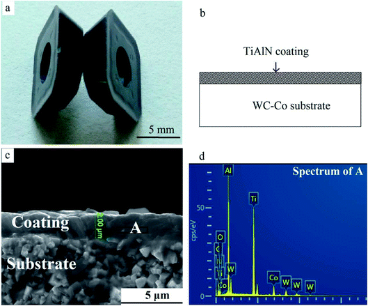 | ||
| Fig. 1 TiAlN hard coating on WC–Co substrates. (a) Macrograph, (b) schematic, (c) cross-sectional SEM image, and (d) the EDS result of area A. | ||
2.2 Experimental procedures
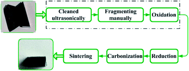
Fig. 2 shows the oxidation and reduction-carbon process for recycling hardmetal scraps.17 In this paper, worn coated cemented carbides were ultrasonically cleaned with acetone, deionized water, and ethanol for 15 min, consecutively. Cleaned insert tips were then placed into drying oven (DZG-6050, Senxin, Shanghai, China) at 100 °C for 1 h. Some dried inserts were subsequently broken into pieces or milled into powders manually. Powders were passed through a 100 mesh sieve and particle size was below 0.15 mm. Untreated inserts, fragments and powders of the same weight were put in to rectangular alumina crucibles, then isothermally maintained in ambient air at 900 °C after heating from room temperature in an electrical resistance furnace (SX2-4-10, Yifeng, Shanghai, China) for 10, 30, 60, 120, and 180 min. Further oxidation time for the whole inserts was prolonged to 240 min for complete oxidation.Chemical phases were examined by X-ray diffraction (XRD, PANalytical, EMPYREAN, Netherlands) in the Bragg–Brentano geometry with Cu-Kα radiation (λ = 0.154 nm) using the continuous scanning mode in 2θ ranging from 10° to 90°. XRD patterns were acquired with a step size of 0.01° and a speed of 2° min−1. The voltage was 40 kV and current was 40 mA. Backscattered electron (BSE) morphologies of samples were observed under vacuum using field emission scanning electron microscope (FESEM, Nova NanoSEM450, FEI, USA), with 20 kV working voltage. The elements' distribution was characterized by energy-dispersive X-ray spectroscopy (EDS, X-max 80, Oxford Instruments, UK). Al concentration was tested using an inductively coupled plasma optical emission spectrometer (ICP-OES, optima 8000, PerkinElmer, USA) with an accuracy of 0.005 mg L−1. Weights were measured using an electronic balance (lucky, Wuxin) with 0.001 g accuracy.
3. Results and discussion
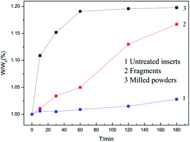
3.1 Oxidation kinetics
Coated hardmetal scraps were oxidized at 900 °C, according to previously published methods,5,18 which was demonstrated in our previous work.17 Fig. 3 illustrates time dependence of the weight ratio (W/W0) when samples were oxidized at 900 °C. W was the oxidation weight and W0 was the weight before oxidation. As shown in Fig. 3, the weight ratio for untreated inserts increased slowly due to the protective coating. For fragments, the weight ratio increased faster as more WC–Co surfaces were exposed to air, but the value only reached about 1.16 when oxidized for 180 min. The coated hardmetal tool tips were milled into powders to accelerate the oxidation process. Fig. 3 illustrates that the weight ratio for powdered samples exhibited parabolic-like behavior. The weight ratio increased rapidly before 60 min. As oxidation continued for 180 min, the weight ratio was ∼1.19, which was almost reached the maximum relative weight gain when fully oxidized.19 These data indicate that total oxides can be obtained when powdered samples with particle size below 0.15 mm are oxidized in air at 900 °C for 180 min.Fig. 4 presents macrographs in the oxidation process. Fig. 4a shows milled powders at different oxidation times. Many black WC particles are clearly visible when oxidized for 10 and 30 min. After oxidation for 60 min, only a few black WC particles were visible, as they were either oxidized or wrapped in oxides. These results were complementary to those in Fig. 3, where the weight ratio was ∼1.18 at that time.19 Powders became completely bluish-gray upon further oxidation for 180 min. According to the result in Fig. 3, they were fully oxidized.
 | ||
| Fig. 4 Macrographs of samples in the oxidation process. (a) Milled powders, (b) whole inserts, and (c) fragments. | ||
Coatings were too small and difficult to find in powdered samples sieved through a 100 mesh screen. In order to study the oxidation behavior of TiAlN hard coating in detail, unfragmented inserts and fragments were oxidized under the same conditions. As shown in Fig. 4b, surface color visibly changed. The coating was violet-grey before oxidation, changed to bright purple, gray and yellowish-gray when oxidized for 30, 60, and 180 min, respectively. This demonstrated phase transition during the oxidation process. Surface color on fragments changed more rapidly (Fig. 4c), indicating a faster oxidation rate. The result revealed that the oxidation rate of milled powders was the most rapid and the slowest of unfragmented inserts. The main reason being that the protective coating inhibited element diffusion. It is proposed that coated hardmetal scraps can be milled into powders before being recycled by the oxidation and reduction-carbon process for accelerating the recycling process.
3.2 Coatings in the oxide powders
Fig. 5 shows the oxide obtained when milled powders were oxidized for 180 min. The black fragment (area A) was seen clearly among white particles. The EDS result displayed that O, Ti, and Al elements were found at point B. The high O and non-existence N content demonstrated that TiAlN were transformed to mixed oxides containing Ti and Al. The concentration of Al was 228 mg kg−1, tested by ICP-OES. Therefore, Al-containing coating was retained in final oxide powders, which would influence the downstream recycling process and recycled products.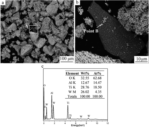 | ||
| Fig. 5 Milled powders oxidized for 180 min. (a) SEM image, (b) magnified image of area A, and (c) the EDS result of point B. | ||
3.3 Phase transitions
Fig. 6 shows that the phases changed with increasing oxidation time. Fig. 6a depicts the XRD results of milled powders below 0.15 mm. Peaks of CoWO4 and WO3 can be found when a number of WC–Co surfaces are oxidized for 10 min. The number of peaks of CoWO4 and WO3 increased upon further oxidation, while the number of WC peaks decreased. After oxidation for 180 min, no WC peak was present, while CoWO4 and WO3 remained. It can be described by the following reactions.19,20
 | (1) |
| WC + 2O2 → WO3 + CO↑ | (2) |
| Co + WC + 3O2 → CoWO4 + CO2↑ | (3) |
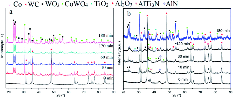 | ||
| Fig. 6 XRD patterns of samples at different oxidation times for (a) milled powders, (b) surface of whole inserts. | ||
At 900 °C, the Gibbs free energy of the above reactions (eqn (1)–(3)) at one atmospheric pressure were approximately −930 kJ, −750 kJ, and −1117 kJ, respectively, according to the reported thermodynamic calculations.5,6,18 They were all below zero, indicating that the above three reactions take place when oxidized under 1 atmospheric pressure at 900 °C. The XRD patterns indicated that the oxidation process can be finished in 180 min for TiAlN coated WC–Co hardmetal powders. The final oxide was mixed with WO3 and CoWO4, which coincided with the results in Fig. 3 and 5. In addition, Al-containing phases were not detected due to their weak signals or they were hidden by the XRD pattern noise.
In order to study the detailed phase evolution of TiAlN coatings, Fig. 6b shows the XRD result for surfaces on whole inserts at different oxidation times. After oxidation for 10 min, peaks of WO3 and CoWO4 from substrate oxides appeared, as the thickness of TiAlN coating in raw material was only ∼2 μm. The peak of AlTi3N and AlN from the TiAlN coating were retained. When oxidized for 30 min, more WO3 and CoWO4 peaks appeared, and the AlN peak was still visible. It has been reported that AlTi3N was decomposed to TiN and AlN.13 TiN-related products cannot be detected due to their limited content. With further oxidation for 120 min, peaks of Al2O3 and TiO2 appeared, which were oxides of TiAlN coatings.10,14 This is in good agreement with EDS result shown in Fig. 5c. Al2O3 signal was weak for its low content or the formation of part amorphous phases.10,21 N element was transformed to N2 and evaporated. The following reaction could be proposed.22
| 2Ti1−xAlxNy + (2 − x/2)O2 → 2(1 − x)TiO2 + xAl2O3 + yN2↑ | (4) |
It is clear that Al2O3 is not easily decomposed or reactive with others under normal condition. It would be the defect, leading to the bad performance of recycled hard alloys. Consequently, Al2O3 poses a big problem for recycling coated hardmetal scraps.15 Therefore, reducing the negative impact will be the focus of our future work.
3.4 Evolution of coatings
Fig. 7 shows SEM images of surfaces at different oxidation times, and Fig. 7a presents the TiAlN coating before oxidation. Pits are visible on the coating, which appeared due to mechanical hitting or stress during the cutting operation. When oxidized for 10 min, more pits and micro-cracks were found. White particles were filled in pits or distributed along cracks, whereas the unbroken coating surface remained smooth, demonstrating that the coating was protective and inhibited elements diffusion. According to the diffusion theory, atoms diffused according to the diffusion coefficient D, which can be expressed as follows:
D = D0![[thin space (1/6-em)]](https://www.rsc.org/images/entities/char_2009.gif) exp(−Q/RT) exp(−Q/RT)
| (5) |
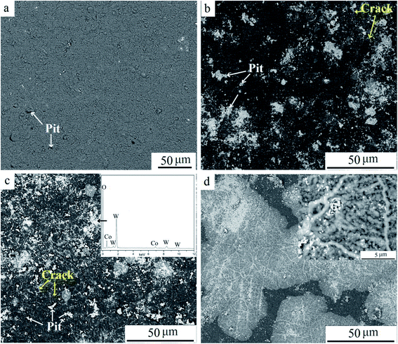 | ||
| Fig. 7 SEM surface images of samples at various oxidation times: (a) 0 min, (b) 10 min, (c) 30 min, and (d) 120 min. | ||
Unfragmented inserts were further oxidized for 240 min to study the elements' distribution in detail, as shown in Fig. 8. Pieces of coating were stripped off the substrate (Fig. 8a and b). On the coating's surface, the pitting like area was visible. There were three distinct regions, the gray area A, the white-gray area B, and the white area C (Fig. 8c), due to the different contents of white WO3. The EDS results show that the content of O in all areas was high, suggesting oxide scale formation.10 The results also showed that the atomic ratio of W element was highest at point C, ∼2.6 times that at point B and 6.5 times that at point A. The significant differential distribution of W can be attributed to rapid element diffusion through defects, uneven distribution of defects, and considerable volatility of WO3 at 900 °C. It is well known that defects provide preferential pathways for element diffusion, as diffusion coefficient D is higher. Thus the outward diffusion of W was mainly via defects such as pits and cracks. Meanwhile, WO3 was notably volatile above 850 °C. A small quantity of WO3 in the substrate evaporated via through-wall cracks and deposited on the surface. As shown in Fig. 8c, area C was filed with white chemicals. Cracks and pits were clearly visible in this area. It was speculated that C was the defects concentrated area. Fewer obvious cracks can be found in region A and the concentration of W was lowest in this area. It confirms that the defect provides preferential pathways for W outward diffusion. Defects on coatings were related to the mechanical damage during the repeated operation before discarded, the stress presented for different thermal expansion coefficients when heated, and porous oxide such as TiO2.17,19 Furthermore, element distribution demonstrated that Al content was higher than that of Ti in respective areas, indicating more Al2O3 on the outmost surface compared to TiO2. This is attributed to the greater affinity of aluminum for oxygen than titanium.
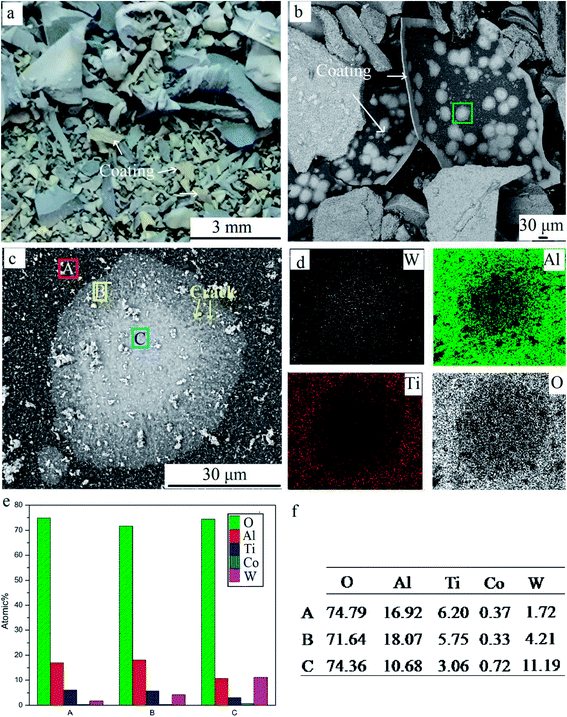 | ||
| Fig. 8 Coatings delaminated from the whole inserts. (a) Macrographs; (b) SEM image; (c) high magnification SEM image; and (d–f) EDS results of three points. | ||
Fig. 9 shows cross-sectional SEM images at different oxidation times. The coating remained dense when oxidized for 10 min. Pits and cracks were visible on the coating after oxidation for 60 min (Fig. 9b). With further oxidation for 240 min, coatings were broken mainly for stress when heated.16 A triple-layer structure can be seen in Fig. 9c. EDS results illustrated that O content was high in all points (Fig. 9d). According to the XRD result in Fig. 6, the layers mainly contained oxides. W, Al, and Ti contents were highest at points A, B, and C, respectively. W and Co contents at point C were both relatively high because the inner coating was in close proximity to the substrate. This implied that the triple-layered oxide scale mainly consisted of a WO3-dominated outmost layer, Al2O3-dominated middle layer, and TiO2-dominated inner layer. This is different from the bilayered Al2O3/TiO2 oxide scale that results during oxidation resistance tests for new TiAlN-coated hardmetals.23 The surface Al2O3 scale was protective and retarded further oxidation in the substrate. Compared to new coated hardmetal, many defects were presented in worn inserts during hitting operation. They provided preferred diffusion pathways, resulting in more W outward diffusion to surfaces. In addition, WO3 distribution on the outmost layer contributed to its volatilization and deposition at 900 °C. This result indicated that WO3, Al2O3, and TiO2 were mixed together in the final oxide scale, and this it was impossible to separate Al2O3. It has been proposed to transform Al2O3 into other chemicals or use it as the reinforcement phase for reducing negative effect. We aim to address this process in our future publication.
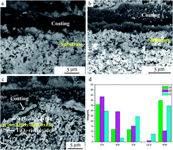 | ||
| Fig. 9 SEM cross-section images of samples at various oxidation times: (a) 10 min, (b) 60 min, (c) 240 min, and (d) EDS result of points. | ||
4. Conclusions
In this study, we investigated the isothermal oxidation of WC–Co cemented carbide inserts covered with TiAlN coating. Time dependence of the weight ratio for milled powders below 0.15 mm showed parabolic-like behavior. Milled powders were totally oxidized to a mixture of WO3 and CoWO4 in 180 min. Pieces of coatings can be found in the final oxide. The TiAlN coating was finally transformed to Al2O3 and TiO2.During oxidation, the coating was protective and caused retarded element diffusion. Oxidation began on the inserts' edges and corners, where defects were concentrated. Defects appeared and promoted due to the repeated cutting operation, stress, and chemicals volatilization. More cracks and pits were found in W-rich regions as oxidation time increased, since the defects provide a fast track for diffusion. It can be speculated that oxidation rates accelerate as more defects are pre-treated, such as shot blasting and quenching.
There were three distinct layers in the oxide scale, comprised of a WO3-dominated outmost layer, an Al2O3-dominated middle layer, and a TiO2-dominated inner layer. Consequently, Al2O3 is difficult to separate alone. Future work will focus on the reduction of Al2O3's harmful influences, or even transform it to behave as the reinforcement phase for improving recycled hardmetals.
Conflicts of interest
The authors declare no conflict of interest.Acknowledgements
This research was funded by the National High-tech Research and Development Program of China (No. 2012AA061902), the National Natural Science Foundation of China (No. 51564036 and 50904035), and the National Key Technology Research and Development Program of China (No. 2011BAC10B04).References
- T. IshIda, T. ITakura, H. MorIguchI and A. Ikegaya, SEI Tech. Rev., 2012, 75, 38–46 Search PubMed.
- I. Konyanshin, et al., US20180274065A1, 2018.
- K. J. Brookes, Met. Powder Rep., 2014, 69, 24–30 CrossRef.
- S. Kim, B. Seo and S. Son, Hydrometallurgy, 2014, 143, 28–33 CrossRef CAS.
- W. Gu, Y. S. Jeong, K. Kim, J. Kim, S. Son and S. Kim, J. Mater. Process. Technol., 2012, 212, 1250–1256 CrossRef CAS.
- H. Kuang, D. Q. Tan, W. He, X. R. Wang, J. Zhong, H. J. Wang and C. H. Yang, Mater. Tehnol., 2017, 51, 997–1003 CrossRef.
- Z. M. Chai, Y. H. Liu, X. C. Lu and D. N. He, RSC Adv., 2014, 4, 51047–51054 RSC.
- C. W. Kim and K. H. Kim, Thin Solid Films, 1997, 307, 113–119 CrossRef CAS.
- Z. Zhou, W. M. Rainforth, C. Rodenburg, N. C. Hyatt, D. B. Lewis and P. E. Hovsepian, Metall. Mater. Trans. A, 2007, 38, 2464–2478 CrossRef.
- Z. T. Wu, P. Sun, Z. B. Qi, B. B. Wei and Z. C. Wang, Vacuum, 2017, 135, 34–43 CrossRef CAS.
- C. M. Koller, R. Hollerweger, C. Sabitzer, R. Rachbauer, S. Kolozsvári, J. Paulitsch and P. H. Mayrhofer, Surf. Coat. Technol., 2014, 259, 599–607 CrossRef CAS.
- B. Grossmann, N. Schalk, C. Czettl, M. Pohler and C. Mitterer, Surf. Coat. Technol., 2017, 309, 687–693 CrossRef CAS.
- E. Aschauer, S. Sackl, T. Schachinger, H. Bolvardi, M. Arndt, P. Polcik, H. Riedl and P. H. Mayrhofer, Surf. Coat. Technol., 2018, 349, 480–487 CrossRef CAS.
- T. Chen, Z. W. Xie, F. Gong, Z. Z. Luo and Z. Yang, Appl. Surf. Sci., 2014, 314, 735–745 CrossRef CAS.
- H. B. Zhu, X. Yang, D. Q. Tan, Y. L. Li, W. He and B. B. Tang, Powder Metall. Mater. Sci. Eng., 2016, 21, 202–208 CrossRef.
- M. Tkadletz, N. Schalk, R. Daniel, J. Keckes, C. Czettl and C. Mitterer, Surf. Coat. Technol., 2016, 285, 31–46 CrossRef CAS.
- H. Kuang, D. Q. Tan, W. He, Z. H. Zhou and X. R. Wang, Materials, 2018, 11, 1796 CrossRef PubMed.
- W. Jung, J. Ind. Eng. Chem., 2014, 20, 2384–2388 CrossRef CAS.
- F. Lofaj and Y. S. Kaganovskii, J. Mater. Sci., 1995, 30, 1811–1817 CrossRef CAS.
- B. X. Liu, A. H. Shi, G. L. Yang, Q. Su, G. G. Chen, L. N. Zhang and B. Yang, Int. J. Refract. Met. Hard Mater., 2017, 67, 74–81 CrossRef CAS.
- B. J. Xiao, H. X. Li, H. J. Mei, W. Dai, F. Zuo, Z. T. Wu and Q. M. Wang, Surf. Coat. Technol., 2018, 333, 229–237 CrossRef CAS.
- P. Panjan, B. Navinšek, M. Čekada and A. Zalar, Vacuum, 1999, 53, 127–131 CrossRef CAS.
- K. Lee, S. Seo and K. Lee, Scr. Mater., 2005, 52, 445–448 CrossRef CAS.
| This journal is © The Royal Society of Chemistry 2019 |

