 Open Access Article
Strategy to construct polyzwitterionic hydrogel coating with antifouling, drag-reducing and weak swelling performance
Jiajia Shen ,
Miao Du
 *,
Ziliang Wu
 ,
Yihu Song
 and
Qiang Zheng
MOE Key Laboratory of Macromolecular Synthesis and Functionalization, Department of Polymer Science and Engineering, Zhejiang University, Hangzhou 310027, China. E-mail: dumiao@zju.edu.cn
First published on 15th January 2019
Abstract
Biological fouling, where marine microorganisms attach densely to various submerged surfaces, has been a serious economic problem worldwide. Different from most antifouling approaches based on stiff and solid materials or coatings, a soft and wet coating composed of zwitterionic polymer was prepared in this paper. With the combination of the anti-polyelectrolyte effect of poly-N-(3-sulfopropyl)-N-(methacryloxyethyl)-N,N-dimethylammonium betaine (PSBMA) and the typical polyelectrolyte effect of polyacrylic acid (PAA), a bicomponent hydrogel coating with weak swelling in saline solution was achieved, which could avoid peeling from solid substrates. The bicomponent hydrogel coating showed strong tensile properties and good compression performance and slipperiness. Although the large Young's modulus of the coating relatively weakens the drag reduction effect, entering the mixed lubrication region in low sliding rate is easy and a low friction coefficient at a high rate could thus be obtained. With the aid of silane coupling agent and weak deformation in water and saline solution, the hydrogel coating could be bound tightly on solid surfaces. After strong sandy water abrasion, the bicomponent hydrogel coating could maintain its original state without any cracks and peeling. The hydrogel coating exhibits good anti-bacterial adhesion and anti-protein adsorption. The bicomponent zwitterionic hydrogel coating reported here provides a new strategy for marine antifouling and drag reduction studies.
1. Introduction
Ships, oil platforms, and other facilities inevitably encounter marine biofouling problems, which is a global problem for marine industry and activities1,2 and has been a serious economic problem worldwide.3,4 Marine biofouling usually occurs on an immersed surface as a result of several successive steps from the formation of a conditioning film followed by the attachment of macroalgae, fungi, protozoa and the last invertebrate larvae.4,5 This phenomenon increases the surface roughness and the weight, causing reduced speed and manoeuvrability of ships, frequent dry-docking cleaning, and high fuel consumption.6Antifouling (AF) compounds and methods have been developed to inhibit fouling by marine organisms. Tributyltin (TBT),6 which exhibits high AF activity, is the most popular AF compound at one time. However, TBT was banned worldwide since 2008 due to its high endocrine disruptive effect (IMO 1999). Exploring novel alternative AF systems is urgently necessary to protect submerged surfaces and marine environment. Several environmentally benign AF approaches have been developed, such as surface coating with natural AF compounds7,8 and fouling-release coatings based on silicones and fluorocarbon polymers that have low surface energy.9,10 Most of these AF approaches are based on stiff and solid materials or coatings, which are effective only on vessels moving at speeds greater than 14 knots (e.g. Intersleek 900).11
Biofouling process is affected by many physical–chemical factors, such as surface tension,12 wettability,13 elastic modulus,14 surface chemistry,15 surface roughness16 and topography.17,18 Considering that the formation of biofilm is a nonspecific and reversible process, highly hydrated surface is proposed as a feasible approach to develop promising materials for fouling resistance applications.19–21 Recently, zwitterionic compounds, including 2-methacryloyloxyethyl phosphorylcholine,22–24 carboxybetaine methacrylate (CBMA), sulfobetaine methacrylate (SBMA)25–30 and so on, have been found to exhibit ultra-low-fouling, indicating that the surfaces coated with these polymers allow less than 5 ng cm−2 of protein adsorption.27–29 The surfaces coated with zwitterionic poly-CBMA highly resist non-specific protein adsorption even from undiluted blood plasma and serum27 and prohibits long-term bacterial colonization by Pseudomonas aeruginosa for up to 10 days at room temperature31 and the attachment of green marine alga, diatoms32,33 and Amphibalanus amphitrite.34 The ultra-low-fouling performance of zwitterionic materials is due to the high hydration around the opposing charges and high energetics required to remove that hydration layer.27,28 However, zwitterionic compounds are usually used in a form of nanofilms by means of superficial atom transfer radical polymerization or layer-by-layer self-assembly, that requires fastidious synthetic conditions35 and is unavailable for large-scale construction of marine AF coatings.
As far as highly hydrated surface is concerned, hydrogel materials, being soft, wet and exhibiting many fascinating properties which cannot be found in solid and liquid materials, followed into our spotlight. The surface properties of hydrogels can be easily modulated by selecting monomer species. Many synthetic polymer hydrogels, including neutral, positively charged and negatively charged hydrogels, exhibit remarkable AF performance against algae15 and barnacle cyprid larvae in vitro.16 Moreover, hydrogels exhibit extremely low surface frictional forces against themselves or solid substrates.10,11,36 Therefore, hydrogels have been investigated as AF material due to its soft surface, drag-reducing effect and low surface energy, just like fish epidermal mucus. Gong et al. reported that one of the key factors of hydrogel AF performance is a low elastic modulus.37 Researchers have successfully developed many new kinds of cross-linked polymer hydrogels for effective marine AF.38–44 Jiang et al. prepared hydrogels with hierarchical surfaces displaying superoleophobicity, which show the potential for AF application.45 All of the hydrogel samples prepared are independent bulk hydrogels that ignore the adhesion between hydrogels and solid substrates. As fouling occurs most in solid surface, such as ship's hulls, aquaculture cages, cooling water intake channels of power plants and so on, the applicability of bulk hydrogels is limited due to the processing difficulty. Another method for hydrogel coating preparation is to blend gel polymer with coating resin, and then a layer of hydrogel is formed on solid surface through water absorption and leaching out of the polymer.46 In addition, Hansen M. R. et al. synthesized a cross-linked zwitterionic thin film to the PDMS surface by the ultraviolet photopolymerization method. The paper paid more attention to the potential of coatings in biological applications, and the film only worked under mild cell and protein adsorption conditions.47 Rosenhahn et al. prepared low fouling thin hydrogel coatings by synthesizing sulfobetaine- and sulfabetaine-bearing zwitterionic copolymers containing a photo-cross-linker.48 These method are not in the preliminary stage of research and is far from actual application in the sea.46,49 Developing absolute hydrogel coatings seems extremely difficult due to its poor adhesive strength to substrates and the strong swelling or shrinking in pure water or saline solution.
In this paper, a zwitterionic hydrogel coating with hydrophilic, soft and slippery submerged surface was prepared on solid surface with strong cohesiveness. SBMA was used to construct the AF and slippery hydrogel coating. Simple SBMA hydrogel coating showed excellent AF and drag-reducing performances; however, the swelling or shrinking behaviors during processing hindered its practical application in harsh marine environment. Poly-SBMA (PSBMA) exhibits antipolyelectrolyte effect, implying that PSBMA hydrogel would swell when transferred from water to saline solution. Conventional water-soluble polymers, especially charged polymers with typical polyelectrolyte effect, were introduced to form bicomponent hydrogel coating to suppress such swelling that would make hydrogel coating be peeled off from the solid substrate. On the other hand, the single PSBMA hydrogel coating is fragile due to its stiff macromolecular chain. The design of such bicomponent hydrogel could improve simultaneously the mechanical properties of hydrogel based on the double network (DN) or interpenetrating network method40 to some extent. Building on the ideas above and the aid of silane coupling agent, tough, antifouling and slippery bicomponent hydrogel coatings adhered on solid substrate were prepared in this paper. The hydrogel swelling behaviors during processing, mechanical properties, anti-bacterial adhesion performance, anti-protein adsorption performance and drag-reduction properties of various coatings (single or bicomponent) were explored in detail.
2. Experimental section
2.1. Materials
N-(3-Sulfopropyl)-N-(methacryloxyethyl)-N,N-dimethyl-ammonium betaine (SBMA), acrylic acid (AA), acrylamide (AM), methyl acrylic acid (MAA), hydroxyethyl methacrylate (HEMA), dimethyl diallyl ammonium chloride (DMDAAC), N,N′-methylenebis acrylamide (MBAA), 2-hydroxyl-4′-(2-hydroxyethoxy)-2-methylpropiophenone (2959), 3-methacryloxypropyl-trimethoxysilane, bovine serum albumin (BSA), and Coomassie Brilliant Blue G-250 were purchased from Shanghai Aladdin Biochemical Technology Co., Ltd. Sea salt was purchased from Guangzhou Yier Biological Engineering Co., Ltd. The water used for all experiments was deionized and supplied by a water purification system. All of the other reagents were used as received without further purification.2.2. Methods
![[thin space (1/6-em)]](https://www.rsc.org/images/entities/char_2009.gif) :
:![[thin space (1/6-em)]](https://www.rsc.org/images/entities/char_2009.gif) 1
1![[thin space (1/6-em)]](https://www.rsc.org/images/entities/char_2009.gif) :
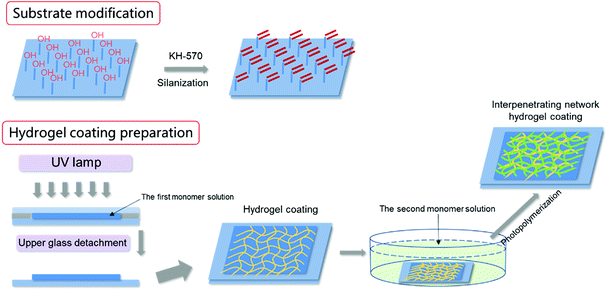
:![[thin space (1/6-em)]](https://www.rsc.org/images/entities/char_2009.gif) 4) for 2 h. After being rinsed with ethanol and dried, the substrates were ready for use. The hydrogel coating was prepared by monomer polymerization directly onto the silanized solid substrates as shown in Scheme 1. The single component hydrogel coatings were prepared through a “sandwich” mould of an untreated glass, the precursor aqueous solution and the silanized substrate (for example, glass) by UV photopolymerization (365 nm wavelength, 30 mW cm−2) for 30 min.38 Subsequently, the hydrogel coatings together with the glass substrate were immersed in pure water for 3 days until they reached swelling equilibrium. For pure PSBMA and PAA hydrogel, the precursor aqueous solutions were composed of 2.5 M SBMA or 3 M AA, 0.5 mol% of cross-linker MBAA, and 0.5 mol% of initiator 2959 (both relative to the monomer).
4) for 2 h. After being rinsed with ethanol and dried, the substrates were ready for use. The hydrogel coating was prepared by monomer polymerization directly onto the silanized solid substrates as shown in Scheme 1. The single component hydrogel coatings were prepared through a “sandwich” mould of an untreated glass, the precursor aqueous solution and the silanized substrate (for example, glass) by UV photopolymerization (365 nm wavelength, 30 mW cm−2) for 30 min.38 Subsequently, the hydrogel coatings together with the glass substrate were immersed in pure water for 3 days until they reached swelling equilibrium. For pure PSBMA and PAA hydrogel, the precursor aqueous solutions were composed of 2.5 M SBMA or 3 M AA, 0.5 mol% of cross-linker MBAA, and 0.5 mol% of initiator 2959 (both relative to the monomer).
The bicomponent hydrogel coatings were prepared by a two-step sequential free-radical polymerization. In the first step, the first network hydrogel coating was prepared as described above. In the second step, the prepared hydrogel coating together with the substrate was immersed into the aqueous solutions containing the second monomer, MBAA and initiator for 16 h. The swollen first network hydrogel was then photopolymerized by UV irradiation in the same way. Subsequently, the hydrogel coatings together with the glass substrate were immersed in pure water for 3 days until they reached swelling equilibrium. The hydrogel coatings on other solid substrates were prepared as the same as described above. If the first network was PSBMA, the second network was polyacrylic acid (PAA), and the ultimate bicomponent hydrogel was denoted as PSBMA/PAA. PAA was the first network, whereas PSBMA was the second network, and the ultimate bicomponent hydrogel was then denoted as PAA/PSBMA. The PAA/PSBMA hydrogels were coded as PAA/PSBMAx, where, x stands for the crosslinker content (mol%, relative to the second monomer). The compositions of the samples synthesized are shown in Table 1. The hydrogel swelling behaviours during processing, mechanical properties, anti-bacterial adhesion performance, anti-protein adsorption performance and drag-reduction properties of various coatings (single or bicomponent) were explored in detail.
| Sample | CAA (M) | CSBMA (M) | CMBAAa (mol%) | CMBAAb (mol%) | Water contentc (wt%) | Ed (kPa) | Tensile strengthd (MPa) | Elongation at breakd (%) | |
|---|---|---|---|---|---|---|---|---|---|
| a Relative to the first monomer.b Relative to the second monomer.c Water content in deionized water.d Tensile results. | |||||||||
| 1 | PAA | 3 | — | 1 | — | 90.75 | 38.3 | 0.037 | 106 |
| 2 | PSBMA | — | 1 | 1 | — | 60.37 | 37.8 | 0.002 | 3 |
| 3 | PSBMA/PAA | 3 | 2.5 | 0.5 | 0.5 | 54.19 | 79.4 | 0.259 | 311 |
| 4 | PAA/PSBMA-i | 3 | 1 | 1 | 0.3 | 48.31 | 98.4 | 0.231 | 199 |
| 5 | PAA/PSBMA0.1% | 3 | 1 | 0.5 | 0.1 | 56.78 | 72.9 | 0.222 | 345 |
| 6 | PAA/PSBMA0.5% | 3 | 1 | 0.5 | 0.5 | 53.62 | 94.1 | 0.212 | 187 |
| 7 | PAA/PSBMA2.0% | 3 | 1 | 0.5 | 2 | 52.21 | 109.5 | 0.396 | 251 |
Compression performances of the hydrogels were measured through compressive test using a tensile-compressive tester (Shenzhen Suns Technology, UTM2000). Samples of 1.05–1.4 mm in thickness were cut into a cylindrical shape with the diameter of 16.5 mm. Hydrogel samples were placed at the centre of the lower compression plate. The sample was then compressed by upper plate, which was connected to a 1000 N load cell at a velocity of 2 mm min−1. The tensile property of hydrogels was measured by using a tensile tester (Instron, 5543A). For the tensile test, samples of 1.05–1.4 mm in thickness were cut into a dumbbell shape (width of 2 mm, length of 12 mm) using a cutter. Tensile velocity was 100 mm min−1. For both compressive and tensile test, the strength and the break strain were determined as the nominal stress and the nominal strain at the failure point, respectively. Young's modulus (E) was also determined as the slope at the 0–0.1 strain range from the stress–strain curve. Measurements were performed at least three times for each sample.
Protein adsorption experiments were carried out in BSA phosphate buffered saline (PBS) solutions with a concentration of 1 mg mL−1. The hydrogel sample with a diameter of 16.5 mm and a thickness of 1.05–1.4 mm was equilibrated in 0.1 M PBS buffer solution (pH 7.4) in a beaker at 37 °C for 24 h on a rotary shaker and then immersed in protein solution at 37 °C for 24 h under the same condition to reach an adsorption–desorption equilibrium. The protein concentration in the solution was quantified through Bradford method.50 1 mL dye reagent containing Coomassie Brilliant Blue G-250 was added into the solution. After incubation for 5 min, the absorbance at a wavelength of 595 nm was measured by a UV-vis spectrophotometer (Shimadzu, UV-1800). The amount of the adsorbed BSA was determined by the difference before and after contact with the hydrogels. A calibration curve between the spectrophotometrical absorbance and the BSA concentration was established to reduce the effect of protein adsorption on the surface of the experimental device. The data were the average of three measurements for each sample.
Escherichia coli (E. coli) and Staphylococcus aureus (S. aureus) were selected as model bacteria to evaluate anti-bacterial adhesion property of the hydrogels. Samples were cut into a wafer shape (with a diameter of 16.5 mm and a thickness of 1.05–1.4 mm). After being sterilized by ultraviolet radiation for 30 min, the hydrogel wafer was co-cultured with E. coli or S. aureus suspension at 106 CFU mL−1 for 12 h, and then the wafers were stained with the LIVE BacLightTM Bacterial Viability Kit and observed under a fluorescence microscope. For each sample, three wafers were tested for fluorescence microscope. Nine different points were measured for each wafer. For the quantitative test, after co-cultured with E. coli or S. aureus suspension at 106 CFU mL−1 for 12 h, the wafers were taken out and placed in 20 mL phosphate buffered saline for 12 h at 37 °C. After 106 times dilution, 100 μL of the bacterial suspension was spread onto the TSA (Tryptic Soy Agar) plate, 3 plates for each sample. The number of viable bacteria was counted after incubation for 12 h.
The static contact angles to water were measured by Harke-SPCA (Harke laboratory apparatus Co. Ltd) in air at room temperature. The volume of the water droplet (6 μL) was maintained constant for all the substrates, and the gravity effect could be neglected. The water on the surface of the hydrogels was removed slightly using a Kimwipe before measurements. The data were the average of five measurements for each sample.
The friction coefficients between glass plate and samples were determined at 25 °C using an AR-G2 rotational rheometer (TA Instruments, USA). The rheometer was equipped with a plate geometry (radius R = 10 mm) and a Peltier plate. The Peltier plate was glued with a glass plate and the plate geometry was glued with samples. For tribological measurements, approximately 0.5 mL of deionized water, 1 M NaCl solution or ASW was placed on the glass plate below and then pressed using the geometry with a normal force (Fn) of 1 N (apparent normal pressure (P) of 3.2 kPa). The rheometer drove the plate geometry to rotate in one direction with a rotating angle velocity (ω), and the torque (T) was recorded. Friction coefficient (μ) was obtained according to μ = T/RFn. To investigate the sliding velocity (v) dependence of friction, we changed ω stepwise from 0.01 rad s−1 to 10 rad s−1 with every single velocity point lasting for 180 s, corresponding to v of 10−3 m s−1 to 10−1 m s−1, and the average torque of the last 150 s was adopted to calculate the friction coefficients.
The abrasion test of hydrogel coatings was carried out as follows. The glass plate with hydrogel coatings was fixed to the inner wall of the beaker (diameter = 10 cm), which was filled with sandy water. The sandy water was stirred up by an electric stirrer with a stirring speed of 700 rad min−1 for 1 h.
3. Results and discussion
3.1. Swelling behavior during hydrogel coating preparation
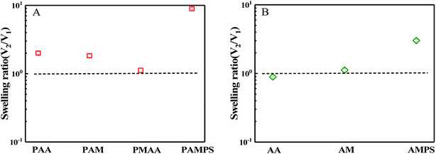
Hydrogels are usually prepared in an aqueous circumstance and will shrink or swell to some extent when immersed into sea water with high salt content. When one side of the hydrogels as a coating is adhered on a solid surface, the swelling or shrinking is anisotropic. Such heterogeneous deformations would cause the coating to partially or completely peel off from the solid substrates. During synthesis of bicomponent hydrogel coating, the first hydrogel network must be immersed into the precursor solution of the second monomer with high concentration. In this case, the first network that has adhered on the substrate might be peeled off due to the shrinking or swelling. Thus, swelling behaviours of the first network in the second monomer precursor solution and the ultimate hydrogel coating in saline solution were first investigated. According to DN hydrogel method,51 the first hydrogel network is composed of crosslinked stiff macromolecules, whereas the second hydrogel network is uncrosslinked flexible polymer chain. In this paper, both the mechanical and the anti-fouling properties of the hydrogel should be considered simultaneously. Although the chains of PSBMA are stiff and the corresponding hydrogel is fragile, the hydrogel coatings with PSBMA as either the first or second network were prepared in this paper. Moreover, the two networks were all crosslinked. Thus, the ultimate hydrogels were termed as bicomponent hydrogel.In the case of PSBMA as the second network, Fig. 1a presents the swelling ratio of the four first hydrogel networks, PAA, polyacrylamide (PAM), polymethacrylic acid (PMAA) and poly(2-acrylamido-2-methylpropanesulfonic acid) (PAMPS), in SBMA monomer solutions with a concentration of 1 M. Here, the swelling ratio is the volume of the hydrogel in the second monomer (i.e. SBMA) solution (V2) to that the volume of the hydrogel just synthesized by using a UV radiation (V1). After transferring from the glass mould into SBMA solution, several hydrogels were all swollen. Possessing large methyl as side group compared with PAA, PMAA hydrogel exhibits a swelling ratio close to 1. PAM hydrogel, as a neutral polymer hydrogel, shows a swelling ratio of 1.8. PAMPS, as a typical anionic polyelectrolyte with sodion as contra-ion, exhibits much large swelling ratio of ∼10. Note that PAA, PAM and PMAA hydrogels show lower swelling ratio than that of PAMPS hydrogel, and the superabsorbent capacity comes from the strong intrinsic polyelectrolyte macromolecules. The swollen balance of these hydrogels in SBMA solution is dependent on the hydrophilicity of the polymer chain, the degree of crosslinking, ion interaction and the osmotic pressure. PMAA chains show relatively weak hydrophilicity owing to the large methyl group and thus low swelling ratio. Although SBMA does contain both positively and negatively charged hydrophilic groups in the same molecules, SBMA is formally uncharged, which causes weak ion interaction between SBMA and the chains of hydrogels. Furthermore, these opposing charges lead to large dipole moments for SBMA molecules with hydrophilicity intermediate between the ionic and conventional nonionic chemicals. In this paper, the concentration of SBMA solution is 1 M, being much higher than its critical micelle concentration,52 implying that most SBMA molecules are in the form of micelles, which generate lower osmotic pressure. All of the mentioned factors above make PAA, PAM and PMAA hydrogels display low swelling ratio in SBMA aqueous solution. Peeling off from the solid substance is difficult if these three hydrogels act as the first network.
In the case of SBMA as the first network, Fig. 1b presents the swelling ratio of the PSBMA hydrogel networks in the second monomer (AA, AM or AMPS) aqueous solution with a concentration of 1 M. After being transferred from the glass mould into AA aqueous solution, PSBMA hydrogel slightly shrank. PSBMA hydrogel could maintain its original shape in AM solution and would neither shrink nor swell. In AMPS solution, the swelling ratio is approximately 3.0, which is the largest one. Note that the swelling ratio of PSBMA hydrogel in the second monomer aqueous solution was much lower than that of PAA, PAM, PMAA and PAMPS hydrogel in SBMA solution owing to the intrinsic zwitterionic character of PSBMA chain. The result of Fig. 1 reveals that AA, MAA and AM could be selected as the other component to construct the bicomponent hydrogel coatings whether SBMA is used as the first or second monomer. Considering that most fouling algae are negatively charged together with the weak swelling during preparation processing, more flexible and negatively charged PAA was selected to construct the bicomponent hydrogel coating with SBMA. Exhibiting the combination of the anti-polyelectrolyte effect of PSBMA and the typical polyelectrolyte effect of PAA, the bicomponent hydrogel coatings would show weak swelling in saline solution and avoid the peeling from solid substrates.
The swollen ratios of PAA, PSBMA, PAA/PSBMA (i.e. PAA/PSBMA-i in Table 1) and PSBMA/PAA hydrogels in NaCl solution at various concentrations and artificial sea water (ASW, sea salt aqueous solutions with a concentration of 3.3 wt%) are shown in Fig. 2. Here, the swollen ratio is the volume of hydrogel in solution (V) to that in deionized water (V0). PAA hydrogel shrinks while PSBMA hydrogel swells in saline solution. PAA hydrogel coating, as a typical anionic polyelectrolyte, exhibits a relatively larger volume in low concentration of saline solution due to electrostatic shielding effect.53 When the concentration of NaCl solution is higher than a certain value, the swollen ratio decreases with concentration, that is, volume collapse occurs and causes shrinkage. The swelling degree of PAA hydrogel in ASW is only 0.3. By contrast, PSBMA hydrogel, as a zwitterionic polymer, exhibits significant antipolyelectrolyte effect, that is, the molecular chains are more stretchable in NaCl solution causing volume expansion and the swollen ratio increases with the concentration of NaCl solution. The swollen ratio of PSBMA hydrogel in ASW is 2.9 or so. Combining the above two polymers with opposite electrolyte effect in saline solution, the hydrogel coating with weak swelling could be achieved. As shown in Fig. 2, both the PAA/PSBMA-i and PSBMA/PAA bicomponent hydrogels exhibit lower swollen ratio than that of single PSBAM and PAA hydrogel in NaCl solution and in ASW (1.5–1.8). Moreover, the swollen ratio for the bicomponent hydrogels changed slightly after varying the concentration of NaCl solution. Increasing the crosslinker loading of PSBMA that acted as the second network (such as PAA/PSBMA0.5%) leads to the smaller swollen ratio and weaker sensitivity to the concentration of NaCl solution.
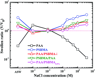 | ||
| Fig. 2 Swollen ratio of PAA, PSBMA, PAA/PSBMA and PSBMA/PAA hydrogel in saline solution and ASW. The samples correspond to those shown in Table 1. | ||
3.2. Tough bicomponent hydrogel
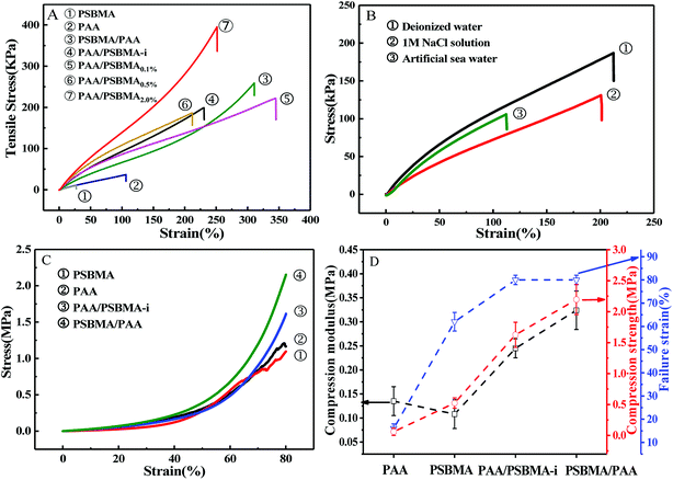
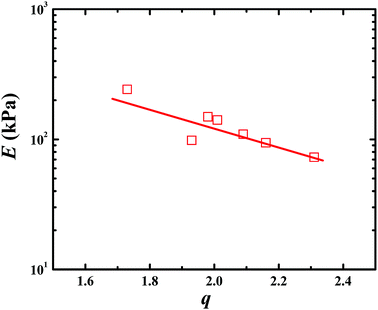
Fig. 3 presents the tensile and compressive stress–strain curves of PAA, PSBMA, PAA/PSBMA-i and PSBMA/PAA hydrogel in water and saline solution. Both PSBMA and PAA hydrogels exhibit low tensile strength (σ) and elastic modulus (E). PSBMA hydrogel is especially fragile in water and its σ and elongation at break (ε) are extremely low, only 2 kPa and 30% respectively, which is not enough to resist water scour as the coating of an immersed surface. After combination with PAA, such as in PAA/PSBMA-i and PSBMA/PAA hydrogels, the mechanical properties were increased remarkably (Fig. 3A). The hydrogel with more crosslinker shows higher E and σ. To further evaluate the marine applicability of PAA/PSBMA-i hydrogel, we performed tensile tests after immersing in 1 M NaCl solution and ASW (Fig. 3B). PAA/PSBMA0.5% with moderate mechanical strength was chosen for the further studies. Both σ and ε of PAA/PSBMA0.5% hydrogel in saline solution decreased due to the slight swelling compared with that in water. Although the mechanical strength decreases, the strength of the bicomponent hydrogel was still high enough to be used in a form of submerged coating and could match the mechanical requirements of many applications for marine field.Besides the tensile mode, the mechanical properties under compressive mode were also measured as shown in Fig. 3C and D. Similar to that under tensile mode, the bicomponent hydrogels exhibited high compressive modulus, strength and failure strain. Given the similar flexibility (or toughness) between PAA and PSBMA, slight difference in mechanical properties was observed for PSBMA/PAA and PAA/PSBMA-i. Swollen degree q (w/w0) is roughly the inverse of polymer volume fraction, E ∝ q−9/4 and E ∝ q−1, which respectively prevail for neutral and polyelectrolyte hydrogels in water at equilibrium swelling state regardless of their preparation conditions.54 To elucidate whether the bicomponent hydrogels behave like typical neutral or polyelectrolyte hydrogels, we plotted the relationship between E and q of the PAA/PSBMA-i hydrogel synthesised at different cross-linker loading and monomer concentrations of the precursor solution, as shown in Fig. 4. We found that the scaling relationship of E and q follows E ∝ q−1.7. The exponent −1.7 is between the theoretical value of −9/4 for a neutral hydrogel and −1 for a polyelectrolyte hydrogel. For a polyzwitterions hydrogel, such as poly(N-(carboxymethyl)-N,N-dimethyl-2-(methacryloyloxy)ethanaminium, inner salt) hydrogel, the exponent is −2.15 because of the presence of both the negatively charged –COO− group and the positively charged R3N+ group and thus behaving as a hydrophilic neutral hydrogel in water.40 The exponent −1.7 of PAA/PSBMA-i hydrogel is lower than −2.15 due to the introduction of polyelectrolyte PAA.
3.3. Anti-bacterial adhesion and anti-protein adsorption
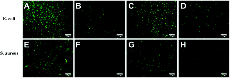
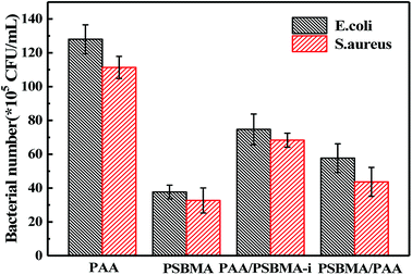
Marine biofouling usually occurs on the immersed surfaces as a result of several successive steps and originates from the formation of a conditioning film, followed by the attachment of macroalgae, fungi, and protozoa to the last invertebrate larvae. The fundamental reason for the fouling of marine organisms is that protein adsorption leads to the growth of bacteria and thus the enrichment of marine organisms. To evaluate the AF property of the as-obtained bicomponent hydrogel coatings, anti-bacterial adhesion and anti-protein adsorption experiments were carried out. Fig. 5 and 6 presents the results of the adsorption tests of Escherichia coli (E. coli) and Staphylococcus aureus (S. aureus) on the four hydrogels, that is, two kinds of single component hydrogels and two kinds of bicomponent hydrogel coatings. PSBMA hydrogel exhibited fewest bacterial adhesion amount attributed to its strong hydrophilicity arising from specific zwitterionic structure, whereas weak polyelectrolyte PAA hydrogel exhibited a certain amount of bacterial adhesion due to its negatively charged surface. The anti-bacterial adhesion of the two bicomponent hydrogel was intermediate between the two single network hydrogels. PSBMA/PAA hydrogel with PSBMA as the first network showed better anti-bacterial adhesion than PAA/PSBMA-i with PAA as the first network, perhaps because of the slightly higher E of PAA/PSBMA-i.55 In addition, the E. coli adhere more than the S. aureus to the four hydrogels. This can be explained in two ways. One is the shape of bacteria. Compared with the spherical S. aureus, the rod-shaped E. coli exhibits larger contact area on the surface of the hydrogel coatings, which makes it easier to be adhered. The second is the thickness and structure of the peptidoglycan layer of bacterial cell wall. E. coli is a kind of Gram-negative bacteria, while S. aureus is Gram-positive bacteria. Gram-negative bacteria E. coli has thinner cell wall as well as more abundant lipid and less peptidoglycan content in cell wall than Gram-positive bacteria—S. aureus. Thus, E. coli is softer than S. aureus which makes it easier to deform and adhere to sample surfaces.Protein adsorption on underwater equipment surfaces is thought to be the first step of many undesired marine biofouling, creating a conditioning film on the substrates, followed by the adhesion of cells and bacteria and colonisation by micro/macroalgae and other macro foulants. The amount of protein adsorbed on the surface is one of the most important factors in evaluating the anti-biofouling property of materials. As shown in Fig. 7A, PSBMA hydrogel showed an excellent anti-protein adsorption performance as expected. The anti-protein adsorption performance of the two bicomponent hydrogel was poorer than that of PSBMA, which was consistent with the results of anti-bacterial adhesion. The other bicomponent hydrogels were obtained by changing the type of the second network using PSBMA as the first network, such as PSBMA/PAM, PSBMA/polyhydroxyethyl methacrylate (PHEMA) and PSBMA/polydimethyl diallyl ammonium chloride (PDMDAAC), and their anti-protein adsorption results are shown in Fig. 7B. Compared with single component hydrogels, the introduction of PSBMA could play a certain effect on inhibiting protein adsorption, in which PSBMA/PAM showed excellent anti-protein adsorption performance. However, the mechanical properties of PSBMA/PAM are too poor to act as a submerged coating.
 | ||
| Fig. 7 (A) BSA adsorption of PAA, PSBMA, PAA/PSBMA-i and PSBMA/PAA hydrogel coatings. (B) BSA adsorption of PAM, PSBMA/PAM, PSBMA/PDMDAAC, PHEMA and PSBMA/PHEMA hydrogel coatings. | ||
3.4. Friction reduction
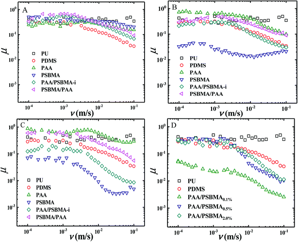
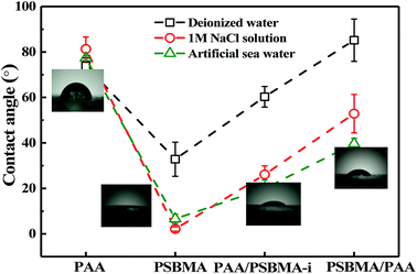
Fig. 8 shows the friction behaviour of the hydrogels in water and saline solution. The friction coefficient (μ) of PU plate, usually as the surface component of ship, did not considerably change with sliding velocity (v) in water. Polydimethylsiloxane (PDMS), with low surface energy, showed a typical Stribeck behaviour, that is, high μ in low v region and then low μ in large v region. The μ ∼ v curves of PAA and PSBMA hydrogels that reached the swollen equilibrium state in deionised almost overlapped with that of PU despite their high water content and did not considerably change with v. The normal strain (λ = P/E, P is the normal pressure) during friction for PAA and PSBMA hydrogel was approximately 8.4%. Under a very large λ, the hydrogels were forced to deform severely and led to large real contact area with the substrate and therefore increased friction. The mixed friction was also difficult to form in this case. The bicomponent hydrogel coating, PAA/PSBMA-i and PSBMA/PAA, exhibited similar friction behaviour to that of PDMS, where a weak mixed friction region could be observed. Usually, a hydrogel with high E could form mixed lubrication in relatively low v due to its large elastic coherence length.56 Thus, high E is effective in reducing the friction at high v region. Note that all the hydrogels in water exhibited friction as high as that of PU.The friction of the hydrogel coatings in 1 M NaCl solution and ASW was shown in Fig. 8B and C. The friction behaviour of PU and PDMS in ASW was the same as that in pure water due to their bulk nonionic character and anhydration. However, the μ of PAA hydrogel was even higher than the μ of PU. In saline solution, PAA chain severely shrunk, and its E increased. Furthermore, PAA hydrogel immersed in saline solution showed a weak attractive interaction with glass surface. By contrast, PSBMA hydrogel coating exhibited much lower μ than that in pure water due to its swelling in saline solution coming from the zwitterionic group on the side of PSBMA chain. The smallest μ was as low as 0.003. Reasonably, PAA/PSBMA-i with SBMA as the second monomer showed lower μ than PSBMA/PAA with AA as the second monomer. For PAA/PSBMA-i hydrogel, the surface bound a large amount of water molecules to form a water layer and PSBMA existed as the second network so that the surface of the hydrogel was mostly composed of PSBMA molecules, which can reduce the friction coefficient through electrostatic hydration. The second monomer played an important role in friction behavior. To validate the surface property difference of these four hydrogels, the contact angle test in air under conditions of deionized water, NaCl solution and ASW was measured. As shown in Fig. 9, the contact angles of water on the four hydrogels in different mediums exhibited the same trend, and PSBMA hydrogel showed a very hydrophilic surface after reaching swelling equilibrium in saline solution and became superhydrophilic, which correlated with the observations in the tribological test.
By changing the crosslinking degree of the second network, we obtained hydrogels with different modulus. Even the hydrogel coatings with high E exhibited a large μ in boundary friction region, entering the mixed lubrication region in a low sliding rate and thus a low μ at a higher rate of 10−2 to 10−1 m s−1 could be easily obtained (Fig. 8D).
3.5. Adhesive and wear
The adhesive state on solid substrates is important to the durability of the soft hydrogel coatings. Silane coupling agent surface treatment allowed easy and tight adherence of the soft coating on conventional solid substrate, such as glass, Al and PU plates, by binding with hydrogel through free radical polymerisation. A test has been performed to examine the robustness of the hydrogel coating. The glass with hydrogel coatings was adhered on the inner wall of a beaker in which sandy water was poured into. With a stirrer, the sandy water was stirred at a rate of 700 rpm for 1 h. Fig. 10 shows the polarizing optical micrograph of the hydrogel coatings before and after sand abrasion. PAA hydrogel coating cracked after sand abrasion and a part edge of the coating was even peeled off. No apparent cracks and splits were observed for the PSBMA and PAA/PSBMA hydrogel coatings, indicating that the surfaces were slippery and the hydrogel coatings were sufficiently tough, and the coatings could maintain the original state even after strong sand abrasion. Unexpectedly, PSBMA/PAA hydrogel coating showed a slight rupture under the microscope which was invisible under naked eye, probably because the surface of the hydrogel coating was mainly composed of the second polymer, PAA. The results of Fig. 10 are consistent with Fig. 8, where PAA hydrogel coating exhibited large μ, whereas the others showed relatively small μ, especially in high sliding velocity. This result indicates that the more slippery the surface is, the less sand abrasion occurs. Furthermore, even under intense scour of sandy water, the hydrogel coatings could not be peeled off the glass surface, indicating the strong cohesiveness between the coating and solid surface.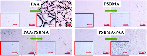 | ||
| Fig. 10 Polarizing optical micrograph of hydrogels before and after sand abrasion with rotating rate = 700 rpm, rotating time = 1 h. | ||
4. Conclusions
Exhibiting the combination of the anti-polyelectrolyte effect of PSBMA and the typical polyelectrolyte effect of PAA, the bicomponent hydrogel coatings with weak swelling in saline solution were achieved, which could avoid the peeling from solid substrates. The bicomponent hydrogel coatings exhibited good mechanical properties and relatively small swelling degree and were slippery. Although the large Young's modulus of the coatings weakens the drag reduction effect relatively, entering the mixed lubrication region in a low sliding rate and thus a low μ at high rate could be easily obtained. With the aid of silane coupling agent together with the weak deformation in water and saline solution, the hydrogel coatings could be bound tightly on the solid surface. After undergoing strong sandy water abrasion, the bicomponent hydrogel coatings maintained their original state without any cracks owing to their slippery surface and tough adhesion. Furthermore, the hydrogel coatings exhibited good AF properties. The bicomponent zwitterionic hydrogel coating reported in this paper provides a new idea for the marine AF and drag-reduction study.Conflicts of interest
The authors declare no conflict of interest.Acknowledgements
This study received funding from the Zhejiang Provincial Natural Science Foundation of China (LY16B040002) and National Natural Science Foundation of China (Grant No. 51673172, No. 51873180 and No. 51333004).References
- M. Wahl, Mar. Ecol.: Prog. Ser., 1989, 58, 175–189 CrossRef.
- L. D. Chambers, K. R. Stokes, F. C. Walsh and R. J. K. Wood, Surf. Coat. Technol., 2006, 201, 3642–3652 CrossRef CAS.
- D. M. Yebra, S. Kiil and K. Dam-Johansen, Prog. Org. Coat., 2004, 50, 75–104 CrossRef CAS.
- S. Dobretsov, H. U. Dahms and P. Y. Qian, Biofouling, 2006, 22, 43 CrossRef CAS PubMed.
- M. G. Hadfield, Biofouling, 1998, 12, 9–29 CrossRef.
- A. Abbott, P. D. Abel, D. W. Arnold and A. Milne, Sci. Total Environ., 2000, 258, 5–19 CrossRef CAS.
- V. Smyrniotopoulos, L. A. Abatis DTziveleka, C. Tsitsimpikou, V. Roussis, A. Loukis and C. Vagias, J. Nat. Prod., 2003, 66, 21–24 CrossRef CAS PubMed.
- J. Zheng, C. Lin, L. Di, D. Duan, D. Hui, W. Li, J. Zhang, Y. Peng and J. Zhou, Adv. Mater. Res., 2009, 79–82, 1079–1082 CAS.
- M. Du, Y. Maki, T. Tominaga, H. Furukawa, J. P. Gong, Y. Osada and Z. Qiang, Macromolecules, 2007, 40, 4313–4321 CrossRef CAS.
- D. L. Schmidt, C. E. Coburn, B. M. Dekoven, G. E. Potter, G. F. Meyers and D. A. Fischer, Nature, 1994, 368, 39–41 CrossRef CAS.
- I. Marabotti, A. Morelli, L. M. Orsini, E. Martinelli, G. Galli, E. Chiellini, E. M. Lien, M. E. Pettitt, M. E. Callow and J. A. Callow, Biofouling, 2009, 25, 481–493 CrossRef CAS PubMed.
- K. Becker and M. Wahl, Biofouling, 1991, 4, 275–291 CrossRef.
- M. Dahlström, H. Jonsson, P. R. Jonsson and H. Elwing, J. Exp. Mar. Biol. Ecol., 2004, 305, 223–232 CrossRef.
- R. F. Brady and I. L. Singer, Biofouling, 2000, 15, 73–81 CrossRef CAS PubMed.
- P. D. Steinberg, N. R. De and S. Kjelleberg, J. Chem. Ecol., 2002, 28, 1935–1951 CrossRef CAS PubMed.
- K. Becker and M. Wahl, Biofouling, 2009, 4, 275–291 CrossRef.
- S. Petronis, K. Berntsson, J. Gold and P. Gatenholm, J. Biomater. Sci., Polym. Ed., 2000, 11, 1051–1072 CrossRef CAS PubMed.
- A. V. Bers and M. Wahl, Biofouling, 2004, 20, 43 CrossRef CAS PubMed.
- T. Ekblad, G. Bergström, T. Ederth, S. L. Conlan, R. Mutton, A. S. Clare, S. Wang, Y. Liu, Q. Zhao and F. D'Souza, Biomacromolecules, 2008, 9, 2775–2783 CrossRef CAS PubMed.
- Z. Hu, L. Chen, D. E. Betts, A. Pandya, M. A. Hillmyer and J. M. Desimone, J. Am. Chem. Soc., 2008, 130, 14244 CrossRef CAS PubMed.
- S. Krishnan, C. J. Weinman and C. K. Ober, J. Mater. Chem., 2008, 18, 3405–3413 RSC.
- J. Park, S. Kurosawa, M. Takai and K. Ishihara, Colloids Surf., B, 2007, 55, 164–172 CrossRef CAS PubMed.
- P. Akkahat, S. Kiatkamjornwong, S. Yusa, V. P. Hoven and Y. Iwasaki, Langmuir, 2012, 28, 5872 CrossRef CAS PubMed.
- S. P. Zhang, L. L. Wang, S. Yang and Y. K. Gong, Sci. China: Chem., 2013, 56, 174–180 CrossRef CAS.
- Z. Zhang, J. A. Finlay, L. Wang, Y. Gao, J. A. Callow, M. E. Callow and S. Jiang, Langmuir, 2009, 25, 13516 CrossRef CAS PubMed.
- S. Jiang and Z. Cao, Adv. Mater., 2010, 22, 920–932 CrossRef CAS PubMed.
- Y. Chang, S. Chen, Q. Yu, Z. Zhang, M. Bernards and S. Jiang, Biomacromolecules, 2007, 8, 122–127 CrossRef CAS PubMed.
- Y. Chang, S. Chen, Z. Zhang and S. Jiang, Langmuir, 2006, 22, 2222–2226 CrossRef CAS PubMed.
- S. Chen and S. Jiang, Adv. Mater., 2010, 20, 335–338 CrossRef.
- Z. Zhang, A. Timothy Chao and S. Jiang, J. Phys. Chem. B, 2008, 112, 5327 CrossRef CAS PubMed.
- Z. Zhang, S. Chen, Y. Chang and S. Jiang, J. Phys. Chem. B, 2006, 110, 10799–10804 CrossRef CAS PubMed.
- G. Cheng, H. Xue, Z. Zhang, S. Chen and S. Jiang, Angew. Chem., 2008, 47, 8831–8834 CrossRef CAS PubMed.
- J. Ladd, Z. Zhang, S. Chen, J. C. Hower and S. Jiang, Biomacromolecules, 2008, 9, 1357–1361 CrossRef CAS PubMed.
- G. Cheng, G. Li, H. Xue, S. Chen, J. D. Bryers and S. Jiang, Biomaterials, 2009, 30, 5234–5240 CrossRef CAS PubMed.
- C. J. Huang, S. H. Chu, C. H. Li and T. R. Lee, Colloids Surf., B, 2016, 145, 291–300 CrossRef CAS PubMed.
- A. E. Meyer, R. E. Baier and R. W. King, Can. J. Chem. Eng., 2010, 66, 55–62 CrossRef.
- T. Murosaki, T. Noguchi, A. Kakugo, A. Putra, T. Kurokawa, H. Furukawa, Y. Osada, J. P. Gong, Y. Nogata and K. Matsumura, Biofouling, 2009, 25, 313 CrossRef CAS PubMed.
- L. R. Carr, Y. Zhou, J. E. Krause, H. Xue and S. Jiang, Biomaterials, 2011, 32, 6893 CrossRef CAS PubMed.
- L. Xie, F. Hong, C. He, C. Ma, J. Liu, G. Zhang and C. Wu, Polymer, 2011, 52, 3738–3744 CrossRef CAS.
- H. Yin, T. Akasaki, T. L. Sun, T. Nakajima, T. Kurokawa, T. Nonoyama, T. Taira, Y. Saruwatari and J. P. Gong, J. Mater. Chem. B, 2013, 1, 3685–3693 RSC.
- L. Xue, X. Lu, H. Wei, P. Long, J. Xu and Y. Zheng, J. Colloid Interface Sci., 2014, 421, 178 CrossRef CAS PubMed.
- M. He, H. Jiang, R. Wang, Y. Xie, W. Zhao and C. Zhao, J. Colloid Interface Sci., 2016, 484, 60–69 CrossRef CAS PubMed.
- M. He, Q. Wang, W. Zhao, J. Li and C. S. Zhao, Polym. Chem., 2017, 8(35), 5344–5353 RSC.
- W. Yang, P. Lin, D. Cheng, L. Zhang, Y. Wu, Y. Liu, X. Pei and F. Zhou, ACS Appl. Mater. Interfaces, 2017, 9, 18295 CrossRef CAS PubMed.
- L. Lin, M. Liu, L. Chen, P. Chen, J. Ma, D. Han and L. Jiang, Adv. Mater., 2010, 22, 4826–4830 CrossRef CAS PubMed.
- J. W. Zhang, C. G. Nin, J. Zhou, L. Wang and J. J. Shao, Mar. Environ. Sci., 2010, 29, 904–907 CAS.
- B. L. Leigh, E. Cheng, L. Xu, A. Derk, M. R. Hansen and C. A. Guymon, Langmuir, 2018 DOI:10.1021/acs.langmuir.8b00838.
- J. Koc, E. Schönemann, A. Amuthalingam, J. Clarke, J. A. Finlay, A. S. Clare, A. Laschewsky and A. Rosenhahn, Langmuir, 2018 DOI:10.1021/acs.langmuir.8b02799.
- J. F. Schumacher, M. L. Carman, T. G. Estes, A. W. Feinberg, L. H. Wilson, M. E. Callow, J. A. Callow, J. A. Finlay and A. B. Brennan, Biofouling, 2007, 23, 55–62 CrossRef CAS PubMed.
- J. B. W. Hammond and N. J. Kruger, Methods Mol. Biol., 1988, 32, 9–15 Search PubMed.
- M. A. Haque, T. Kurokawa and J. P. Gong, Polymer, 2012, 53, 1805–1822 CrossRef CAS.
- A. Bhatia and S. Qutubuddin, Colloids Surf., 1993, 69, 277–292 CrossRef CAS.
- Y. Wu, J. Liang, F. Horkay and M. Libera, J. Polym. Sci., Part B: Polym. Phys., 2016, 54, 64–72 CrossRef CAS.
- H. Yin, T. Akasaki, T. Linsun, T. Nakajima, T. Kurokawa, T. Nonoyama, T. Taira, Y. Saruwatari and J. Pinggong, J. Mater. Chem. B, 2013, 1, 3685–3693 RSC.
- T. Murosaki, N. Ahmed and J. P. Gong, Sci. Technol. Adv. Mater., 2012, 12, 064706 CrossRef PubMed.
- P. Xu, M. Du and Q. Zheng, Acta Polym. Sin., 2014, 708–714 CAS.
| This journal is © The Royal Society of Chemistry 2019 |

