 Open Access Article
High dispersion and oxygen reduction reaction activity of Co3O4 nanoparticles on platelet-type carbon nanofibers
Naohito Yamadaa,
Damian Kowalski b,
Akira Koyamab,
Chunyu Zhu
 ab,
Yoshitaka Aoki
 ab and
Hiroki Habazaki
 *ab
*ab
aFaculty of Engineering, Hokkaido University, Sapporo, Hokkaido 060-8628, Japan. E-mail: habazaki@eng.hokudai.ac.jp
bGraduate School of Chemical Sciences and Engineering, Hokkaido University, Sapporo, Hokkaido 060-8628, Japan
First published on 28th January 2019
Abstract
In this study, platelet-type carbon nanofibers prepared by the liquid phase carbonization of polymers in the pores of a porous anodic alumina template were used to prepare the Co3O4/carbon electrocatalysts. For comparison, Co3O4 nanoparticles were also deposited on multiwall carbon nanotubes (MWCNTs). Both the nitrogen-free platelet-type carbon nanofibers (pCNFs) and the nitrogen-containing analogue (N-pCNFs) exhibited better dispersion and higher amount of deposited Co3O4 nanoparticles compared to the MWCNTs. In addition, many individual Co3O4 nanoparticles were deposited separately on pCNF and N-pCNF, whereas aggregated deposition was commonplace on MWCNTs. The results indicated that the side wall of the pCNFs, which consisted of carbon edge planes, was the preferential nucleation site of Co3O4 nanoparticles rather than the basal planes of carbon that predominated the surface of the MWCNTs. The oxygen reduction reaction (ORR) activity of the Co3O4/pCNF composite in 0.1 mol dm−3 KOH solution was better than that of Co3O4/MWCNTs. The N-pCNF further enhanced the ORR activity of the Co3O4/pCNFs even though the dispersion and supported amount of Co3O4 nanoparticles were negligibly affected by the presence of the nitrogen species. Synergistic interactions of the Co3O4 nanoparticles with N-doped CNFs contributed to the increased ORR activity.
Introduction
Oxygen evolution reaction (OER) and oxygen reduction reaction (ORR) in acid and alkaline media are the primary electrochemical reactions operating in metal–air secondary batteries, regenerative fuel cells, and water splitting. Metal–air batteries and fuel cells are highly promising electrochemical energy storage and conversion systems with extremely high theoretical energy densities and have been studied extensively for future applications.1,2 As the kinetics of ORR and OER are sluggish, efficient electrocatalysts are required to accelerate these reactions and improve the efficiency of the metal–air battery and fuel cell systems. It is well known that platinum and iridium/ruthenium oxides are the benchmark electrocatalysts for ORR and OER, respectively, showing relatively high activity at low overpotentials.3–6 However, the scarcity and high cost of these noble metal elements limits their large-scale commercialization. It is, therefore, of recent great interest to develop noble metal-free ORR and OER electrocatalysts with high activity and durability.7–10Noble metal-free oxide/carbon composites are promising electrocatalysts for ORR and OER. Such electrocatalysts must allow high electric conductivity to ensure a high reaction current. As most noble metal-free oxides possess insufficient electric conductivity at room temperature, conductive nanocarbon materials such as carbon black, carbon nanotubes, and reduced graphene oxide are added to the oxides to form highly active ORR and OER electrodes. The oxide/carbon composites are usually prepared by either physical mixing or chemical synthesis. Compared to physical mixing, the chemical approach allows stronger oxide/carbon coupling interactions and better dispersion of each component.11–14 For instance, Co3O4/carbon composites with oxidized carbon nanotubes and reduced graphene oxide with and without nitrogen doping were prepared by a chemical approach, and the composites with the strong Co3O4–carbon interaction exhibited much higher activity for ORR and OER in comparison with either Co3O4 or carbon alone as well as a physical mixture of Co3O4 and carbon.13,14
Apart from the key role of carbon as a conductive support in oxide/carbon composite electrocatalysts, recent studies have pointed out the direct participation of carbon in the ORR pathway as a catalyst for the first step of O2 reduction to HO2− in alkaline solutions.15–17 The basic reactions of oxygen reduction in an alkaline solution are shown in the following equations.18
| O2 + 2H2O + 4e− → 4OH− | (1) |
| O2 + H2O + 2e− → HO2− + OH− | (2) |
| HO2− + H2O + 2e− → 3OH− | (3) |
| 2HO2− → 2OH− + O2 | (4) |
Nishio et al. have reported that gas-diffusion electrodes containing perovskite oxides such as La0.5Sr0.5CoO3, LaNiO3, La0.6Sr0.4FeO3, LaMnO3, and carbon black exhibit much higher ORR activity as compared to the respective carbon-free electrodes in an alkaline electrolyte.19,20 Upon addition of carbon, the enhancement of the ORR activity was remarkably higher than the moderate enhancement of OER activity, suggesting that carbon played an additional role in the ORR besides the enhanced electric conductivity. The authors proposed that the ORR proceeds via the peroxide pathway; carbon promotes the two-electron reduction of O2 to HO2− (eqn (2)) and the perovskite oxides are active for electroreduction or chemical decomposition of HO2− (eqn (3) or (4)).
It has also been reported that strongly coupled interactions between the oxide and carbon additive enhance the ORR activity. For instance, Dai et al. demonstrated that the strongly coupled Co3O4/N-doped reduced graphene oxide composites exhibit highly enhanced ORR activity, which they explained to be a result of the synergistic chemical coupling between Co3O4 and N-doped reduced graphene oxide.14
These previous findings suggest that the carbon structure and composition have a significant effect on the ORR performance of the oxide/carbon composite electrodes. In addition to the catalytic properties of the oxide itself, a uniform dispersion of oxide nanoparticles is important to increase the active surface area and develop a good electrical conduction pathway. The strong chemical interaction at the oxide/carbon interface is likely to enhance the ORR activity. Compared to the basal plane of graphitic carbon, the edge plane is more active in its interaction with the oxide nanoparticles and probably more suitable for the uniform dispersion and strong interaction to oxide nanoparticles. Therefore, carbon materials with a high density of edge planes are a suitable choice for fabricating highly active oxide nanoparticles/carbon composite electrodes for ORR.
In this study, platelet-type carbon nanofibers were used as a carbon support of Co3O4 nanoparticles. Zheng et al. have previously prepared Pt nanoparticles supported on platelet, fish-bone, and tubular-type carbon nanofibers (CNFs), and found that the Pt on platelet-type carbon nanofibers had a smaller Pt particle size and stronger Pt–carbon interactions, exhibiting better ORR activity compared to the Pt on the fish-bone- and tubular-type CNFs.21 Tsuji et al. have reported that the Pt nanoparticles were uniformly dispersed on the platelet-type CNFs and these composites had highly improved durability for ORR in sulfuric acid solution because of the strong interaction between Pt nanoparticles and the CNFs that inhibited the migration of Pt on carbon.22 Based on these findings, it was concluded that platelet-type CNFs are promising options for the preparation of oxide/carbon electrocatalysts with a uniform dispersion of oxide nanoparticles and a strong oxide–carbon interaction, leading to the enhanced ORR activity. In the present study, Co3O4 nanoparticles were deposited on the platelet-type CNFs with and without nitrogen doping and the ORR activity was examined in alkaline KOH solution. The Co3O4 dispersion and ORR activity of these composites were compared with those of Co3O4 nanoparticles deposited on multiwalled carbon nanotubes (MWCNTs).
Experimental
Materials preparation
CNFs with and without nitrogen species were prepared by liquid phase carbonization of polymer powders in a porous anodic alumina template.23,24 The porous anodic alumina template was prepared by anodizing a 99.99% pure aluminum sheet of 0.1 mm thickness at 40 V in 0.3 mol dm−3 oxalic acid solution for 2 h at 293 K. Subsequent pore widening treatment, i.e., immersion of the anodized specimen in 5 wt% phosphoric acid at 303 K for 20 min, was also conducted to control the diameter of the cylindrical pores to ∼50 nm.The CNFs were prepared by heating a mixture of the template and polyvinyl chloride (PVC) powders (Shin-Etsu Chemicals, TK-2500) or polyacrylamide (PAA) powders (Kishida Chemical) at 573 K for 40 min and then at 873 K for 1 h in a high purity Ar (99.999%) atmosphere. The heating rate to the prescribed temperatures was 400 K h−1. Then, the template was dissolved in 10% NaOH solution and CNFs were obtained. Finally, the obtained CNFs were heat-treated at 1373 K for 1 h in a high purity Ar atmosphere. Hereafter, the CNFs derived from PVC and PAA are denoted as pCNF and N-pCNF, respectively. For comparison, the commercial MWCNTs (Sigma Aldrich) were also used as a support for Co3O4.
Co3O4/carbon electrocatalysts were prepared as follows. The pCNFs, N-pCNFs, or MWCNTs (30 mg) were dispersed in ethanol (37.5 mL) ultrasonically for 30 min. After the addition of 0.1 mol dm−3 cobalt(II) acetate aqueous solution (1.6 mL) and 28% ammonia solution (0.6 mL), the mixture was stirred for 30 min, and the precipitation reaction of Co3O4 was performed at 353 K for 12 h. Finally, the carbon-supported Co3O4 were filtered and dried in air.
Materials characterization
The morphology and structure of the carbon materials with and without Co3O4 nanoparticles were characterized using the Sigma-500 (ZEISS) field-emission scanning electron microscope (SEM) operated at 1.5 kV or less and the JEM-2010F (JEOL) field emission transmission electron microscope (TEM) operated at 200 kV. In addition, the degree of graphitization and phase of Co3O4 were identified by the RINT2200 (Rigaku) X-ray diffractometer with Cu Kα radiation (λ = 015418 nm) and XproRA (Horiba Scientific) Raman spectrometer with laser wavelength of 532 nm. The specific surface areas of the specimens were examined by nitrogen gas adsorption/desorption at 77 K using Belsorp-mini equipment (Bel Japan). Prior to the measurements, the specimens were heat-treated in vacuo at 473 K for 3 h. The amount of Co3O4 loading on the carbon supports was evaluated by a Netzsch, STA 2500 Regulus TG-DSC system, operated in air at a heating rate of 20 K min−1 to 1273 K. The nitrogen content and nitrogen species in the N-pCNFs were examined by a JEOL, JPS-9200 X-ray photoelectron spectrometer (XPS) with Mg Kα (1253.6 eV) excitation.Electrochemical measurements
A rotating ring-disk electrode (RRDE) system with a platinum ring electrode, connected with a Princeton Applied Research, VersaSTAT 4 potentiostat/galvanostat, was used to conduct the electrochemical measurements. A Pt sheet was used as a counter electrode, whereas the reference electrode was the Ag/AgCl electrode with saturated KCl solution electrolyte. The potential values in this paper have been referenced to the reversible hydrogen electrode (RHE). The working electrodes were glassy carbon (GC) disk electrodes (5 mm in diameter) coated with Co3O4/carbon or carbon materials. The coating was conducted as follows. First, a catalyst ink was prepared by mixing Co3O4/carbon or carbon powders (1 mg), ethanol (120 μL), Milli-Q water (120 μL), and 5% Nafion® solution (10 μL) ultrasonically. The ink (5 μL) was coated on the GC electrode. After drying in air, the coated electrode was heat-treated at 333 K for 5 min. The electrochemical measurements were conducted in Ar or O2 saturated 0.1 mol dm−3 KOH solution at room temperature. Cyclic voltammograms were obtained at a potential sweep rate of 100 mV s−1 in the potential range between 0.05 and 1.2 V vs. RHE in the Ar-saturated solution. The capacitance of the electrode, C, was estimated using the following equation;
 | (5) |
 | (6) |
Results and discussion
Characterization of carbon
Fig. 1 shows the scanning electron micrographs of carbon materials used in this study. The pCNFs (Fig. 1a) and N-pCNFs (Fig. 1b) exhibited nanofiber morphology and had diameters of ∼50 nm, which corresponded to the pore size of the porous anodic alumina template. The length of the nanofibers was less than 1 μm, being much shorter than the length of the cylindrical pore channels in the template (∼20 μm). The formation of short nanofibers was associated with the trapping of gaseous species generated during carbonization of the polymers in the cylindrical pores as well as the poor mechanical strength of platelet-type CNFs.24 The commercially available MWCNTs used in this study (Fig. 1c) had diameters in the range of 50–200 nm with the length being much larger than 5 μm. Therefore, the aspect ratio of the MWCNTs was larger than that of the pCNFs and N-pCNFs.Further detailed structure of the carbon materials was examined using TEM (Fig. 2). It is evident from Fig. 2a and b that there were hollow regions, as indicated by arrows, in the pCNFs and N-pCNFs, which had probably developed because of gas generation during the carbonization of polymers in the pores of the template. The high magnification images of these two carbon nanofibers revealed their platelet structure with the carbon layers approximately normal to the fiber axis (Fig. 2d and e). The nanotubular morphology of the MWCNTs can be clearly seen in Fig. 2c; the multi-walled carbon layers were parallel to the tube axis (Fig. 2f), in contrast to the platelet structure of the pCNFs and N-pCNFs. Thus, the basal planes of carbon were predominantly exposed at the side wall of the MWCNTs, whereas the side wall of the pCNFs and N-pCNFs was mainly composed of the edge planes of graphitic carbon.
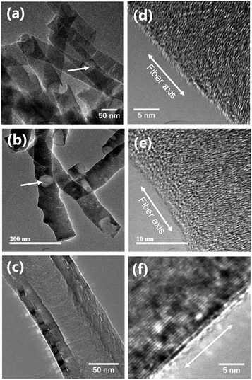 | ||
| Fig. 2 Transmission electron micrographs of (a and d) pCNFs, (b and e) N-pCNFs, and (c and f) MWCNTs. | ||
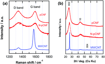
The graphitization degree was further examined by Raman spectroscopy and XRD. Raman spectroscopy is a powerful tool to characterize carbon materials.25,26 Highly graphitic carbon, such as highly oriented pyrolytic graphite (HOPG), exhibited a main first order E2g peak at 1582 cm−1, often referred to as the G band. When disorder was introduced into the graphite structure, additional peaks appeared at ∼1350 cm−1 (D band) and ∼1620 cm−1 (D′ band) in addition to the broadening of the G band. The intensity ratio of the D band to the G band (ID/IG) is often used to evaluate the graphitization degree of carbon materials. It has been previously reported that the ID/IG ratio is inversely proportional to the size of graphitic crystals, which can be determined by peak broadening of the 002 refection in the XRD pattern.27–29
The Raman spectra of the three carbon materials are plotted in Fig. 3a and their ID/IG ratios are listed in Table 1. Both the D and G bands were visible in the spectra of all carbon materials, although their intensity ratios differed widely. The MWCNTs exhibited the lowest D band intensity and the sharpest G band, suggesting the highest graphitization degree. This observation was also supported by the ID/IG ratio (Table 1). The peak position of the G band of MWCNTs was slightly lower than those of the other three carbon materials, probably reflecting the very weak D′ band (∼1620 cm−1) for the MWCNTs. The similar ID/IG ratios of pCNFs and N-pCNFs suggests that they also had similar degrees of graphitization. This was also confirmed by XRD patterns (Fig. 3b). The MWCNTs showed a sharp 002 reflection at 28° whereas pCNFs and N-pCNFs showed a similar broad 002 reflection.
| Raman ID/IG | LC (002) (nm) | BET (m2 g−1) | Capacitance (mF cm−2) | ORR onset potential (V vs. RHE) | ORR electron transfer number (0.7 V vs. RHE) | |
|---|---|---|---|---|---|---|
| pCNFs | 1.25 | 1.9 | 43.2 | 20.8 | 0.790 | 2.62 |
| N-pCNFs | 1.01 | 2.1 | 63.4 | 20.7 | 0.854 | 3.00 |
| MWCNTs | 0.19 | 16.0 | 79.2 | 7.7 | 0.723 | 3.04 |
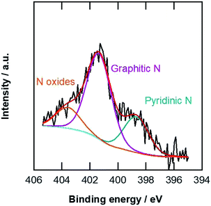
The specific surface areas of the carbon materials were examined by nitrogen adsorption at 77 K. The Brunauer–Emmett–Teller (BET) specific surface areas listed in Table 1 indicate that the pCNFs had slightly lower specific surface areas compared with the N-pCNFs, being nearly half that of the MWCNTs. The N-pCNFs contain nitrogen species because the polymer precursor (PAA) has an amide group. Fig. 4 shows the N 1s XPS spectrum of the N-pCNFs. The following three types of nitrogen species were identified; pyridinic nitrogen with a peak binding energy of 398.8 eV, graphitic nitrogen at 401.4 eV, and oxidized nitrogen species at 403.6 eV.30 The major nitrogen species was graphitic nitrogen and pyrrolic nitrogen was not resolved in the present N-pCNFs. It has been reported that pyridinic nitrogen creates Lewis basic sites and enhances the ORR activity.8 From the XPS quantitative analysis, the nitrogen content in the N-pCNFs was determined to be 2.6 at% and that of pyridinic nitrogen was only 0.7 at%.
Characterization of Co3O4/carbon materials
Co3O4 nanoparticles were deposited on the three types of carbon materials. Fig. 5 shows the scanning electron micrographs of the Co3O4/carbon composites. Nanoparticles with a lighter appearance in these backscattering images correspond to Co3O4 and the carbon materials appear dark because of lower atonic number of carbon. It was evident that higher amounts of Co3O4 nanoparticles were deposited on pCNFs and N-pCNFs as compared with the MWCNTs. The Co3O4 content in the Co3O4/carbon composites was determined by thermogravimetric analysis. The content of Co3O4 in the composites was estimated (Table 2) from the mass loss of the composites during heating in air because of oxidative consumption of carbon and transformation of Co3O4 to CoO. The Co3O4 content on the pCNFs was similar to that on the N-pCNFs, whereas that on the MWCNTs was approximately half of that on the pCNFs. Thus, it is reasonable to assume that the Co3O4 nanoparticles prefer to deposit on the carbon edge planes on the pCNFs as compared to the carbon basal planes.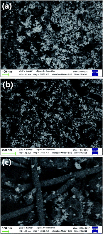 | ||
| Fig. 5 Backscattered electron scanning electron micrographs of (a) Co3O4/pCNF, (b) Co3O4/N-pCNF, and (c) Co3O4/MWCNT. | ||
| Co3O4 content (wt%) | Anodic peak current (mA cm−2) | ORR current at 0.8 V vs. RHE (mA cm−2) | ORR onset potential (V vs. RHE) | ORR electron transfer number (0.7 V vs. RHE) | |
|---|---|---|---|---|---|
| Co3O4/pCNF | 39.7 | 1.08 | 1.20 | 0.887 | 3.81 |
| Co3O4/N-pCNF | 33.1 | 1.15 | 2.52 | 0.906 | 3.88 |
| Co3O4/MWCNT | 18.4 | 0.50 | 0.16 | 0.828 | 3.72 |
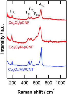
The high-resolution transmission electron micrograph of the Co3O4/pCNF composite (Fig. 6a) revealed that the deposition of highly crystalline Co3O4 nanoparticles on the platelet-type carbon nanofibers. The Co3O4 nanoparticles deposited on all carbon materials showed high crystallinity (Fig. 6). The size of the Co3O4 nanoparticles was 4–10 nm. On the platelet-type carbon nanofibers (Fig. 6a and b), a high percentage of Co3O4 nanoparticles were directly deposited on the carbon surface, whereas the Co3O4 nanoparticles deposited on the MWCNTs would often form agglomerates. Our findings suggested that the carbon edge planes on the platelet-type carbon nanofibers were the preferred nucleation sites of the Co3O4 nanoparticles. In contrast, the basal planes of carbon were less active for Co3O4 nucleation, resulting in the agglomeration of the Co3O4 nanoparticles. The formation of the Co3O4 phase was identified by Raman spectroscopy (Fig. 7). All peaks found in the Raman spectra could be assigned to Co3O4.
 | ||
| Fig. 6 High-resolution transmission electron micrographs of (a) Co3O4/pCNF, (b) Co3O4/N-pCNF and (c) Co3O4/MWCNT. | ||
Electrochemical characteristics
Fig. 8 shows the cyclic voltammograms of the three types of carbon materials measured in 0.1 mol dm−3 KOH solution. The shape of cyclic voltammogram deviates to some extent from ideal rectangular shape, which is typical of double layer capacitive behavior without redox reaction. The current density of pCNFs was similar to that of N-pCNFs, but that of MWCNTs was almost half those of the pCNFs and N-pCNFs. The capacitance of each carbon material was estimated from the cyclic voltammograms and the results are summarized in Table 1. The pCNFs and N-pCNFs showed similar capacitance even though the latter contained nitrogen species, which usually enhance the capacitance because of pseudocapacitance.31 There was no obvious enhancement of the capacitance by nitrogen doping, which may be attributed to the relatively low level of nitrogen content (<3 at% by XPS) in the N-pCNFs. The capacitance of MWCNTs was less than half those of pCNFs and N-pCNFs, even though the specific surface area of MWCNTs was larger than that of the platelet-type carbon nanofibers. The difference in capacity is probably associated with the larger double layer capacitance of the edge plane of graphite compared with the basal plane.32,33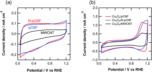 | ||
| Fig. 8 Cyclic voltammograms of the (a) three carbon materials and (b) Co3O4/carbon composites in Ar-saturated 0.1 mol dm−3 KOH solution at room temperature. | ||
The cyclic voltammograms of the Co3O4/carbon composites (Fig. 8b) reveal a redox peak above 0.8 V vs. RHE, which is associated with the following reaction.13
| Co3O4 + OH− + H2O ⇄ 3CoOOH + e− | (7) |
The anodic peak current of the pCNFs and N-pCNFs with Co3O4 was larger than that of the MWCNTs, because of the higher amount of Co3O4 deposition of the former two composites. The anodic peak current of the Co3O4/MWCNT composite was half that of Co3O4/pCNF, which was consistent with the loading amount of Co3O4.
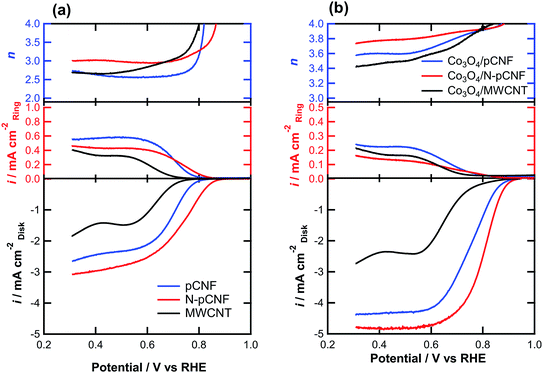
The ORR activity was examined by linear sweep voltammetry (LSV) on a RRDE in O2-saturated 0.1 mol dm−3 KOH solution for carbon and Co3O4/carbon composites (Fig. 9). The N-pCNFs showed the highest ORR onset potential, defined as the potential at 0.1 mA cm−2, among the Co3O4-free carbon materials (Table 1). The increased ORR activity may be associated with the presence of nitrogen species that introduce the ORR active sites. The nitrogen-free pCNFs showed a nobler onset potential compared to the MWCNTs, suggesting that the edge planes of carbon, which are mainly present at the side wall of pCNFs, were more active for ORR than the basal planes exposed at the side wall of the MWCNTs. From the ring current, the formation of HO2− by the two-electron reduction of O2 was obvious. The electron transfer number was ∼3.0 or less and thus, the four-electron reduction was not predominant.
When the Co3O4/carbon composites were used as electrocatalysts, a significant ennoblement of the onset potential to ∼0.9 V vs. RHE was found (Fig. 9b). In addition, the limiting current density increased significantly by the addition of Co3O4 (Fig. 9). This is owing to the increased electron transfer number for ORR as confirmed from the ring current; a lower ring current was observed for the Co3O4/carbon composites as compared to the Co3O4-free carbon materials (Fig. 9a) even though the disk current was higher. The Co3O4/carbon composites had higher electron transfer numbers than the Co3O4-free carbon materials, and the value for the Co3O4/N-pCNF composite was as high as ∼3.9. The higher electron transfer number and higher ORR current of Co3O4/N-pCNF in comparison with the other two composites may be attributed to a positive effect of nitrogen doping of pCNF on the ORR activity. The onset potential of the present Co3O4/N-pCNF is slightly better than those of the previously reported Co3O4/N-doped Vulcan carbon34 and Co@Co3O4@N-doped carbon core/shell35 electrocatalysts.
The ORR current densities of the Co3O4/carbon composites at 0.8 V vs. RHE, at which the current is apparently controlled by charge transfer, were compared (Table 2). The current density of the Co3O4/MWCNT composite was only 0.16 mA cm−2, which is almost one order of magnitude lower than that of Co3O4/pCNF. Such a low activity of Co3O4/MWCNT for ORR may not be simply explained by the lower Co3O4 loading on the MWCNTs. In fact, the ORR activity of the Co3O4/MWCNT was still much lower than that of Co3O4/pCNF when the Co3O4 loading on MWCNT was increased to 44 wt% by increasing the cobalt(II) acetate concentration in the deposition solution. The Co3O4 nanoparticles are mainly deposited individually on the pCNFs and agglomerated nanoparticles are predominant on the MWCNTs. The individual deposition of Co3O4 nanoparticles on carbon is preferable to ensure a sufficient electron conducting path from the current collector to the Co3O4 electrocatalyst. In addition, the strong Co3O4–carbon coupling, which is important to enhance the catalytic activity,11–13,36 could also contribute to the enhanced activity of Co3O4/pCNF. Further increase in the activity of the Co3O4/N-pCNF composite appears to be associated with the nitrogen doping effect of carbon, as reported previously.14 The synergistic effect of Co3O4 and N-doped carbon contributes to the enhanced ORR activity, although the detailed mechanism is still unclear.
It is worth mentioning that uniform dispersions of Co3O4 nanoparticles on carbon nanotubes have been previously reported.13,37 However, the introduction of the surface functional group on the side wall of carbon nanotubes is always necessary for a uniform dispersion of oxide nanoparticles. The present study demonstrates that when platelet-type carbon nanofibers are used as a support of oxide nanoparticles, the introduction of surface functional groups is not necessary, and as-formed pCNF can be utilized because of the high reactivity of the edge planes of carbon.
Conclusions
The present study demonstrates that platelet carbon nanofibers with edge planes of carbon at their side wall were a suitable support for Co3O4 nanoparticles. Without any pre-treatment to introduce the surface functional groups to carbon, the nanoparticles could be uniformly and individually dispersed on the side walls of the carbon nanofibers. The edge planes of carbon were the preferred sites for the deposition of oxide nanoparticles. The Co3O4/pCNF composite showed high ORR activity in alkaline solution and doping of pCNFs with nitrogen further enhanced the ORR activity.Conflicts of interest
Authors declare no conflict of interest.Acknowledgements
The present study was supported in part by JSPS KAKENHI grant number 16H04530. A part of this work was conducted at Hokkaido University, supported by the “Nanotechnology Platform” Program of the Ministry of Education, Culture, Sports, Science and Technology (MEXT), Japan.References
- O. Z. Sharaf and M. F. Orhan, Renewable Sustainable Energy Rev., 2014, 32, 810–853 CrossRef CAS.
- Y. G. Li and H. J. Dai, Chem. Soc. Rev., 2014, 43, 5257–5275 RSC.
- M. H. Shao, Q. W. Chang, J. P. Dodelet and R. Chenitz, Chem. Rev., 2016, 116, 3594–3657 CrossRef CAS PubMed.
- Y. Nie, L. Li and Z. D. Wei, Chem. Soc. Rev., 2015, 44, 2168–2201 RSC.
- S. Cherevko, S. Geiger, O. Kasian, N. Kulyk, J. P. Grote, A. Savan, B. R. Shrestha, S. Merzlikin, B. Breitbach, A. Ludwig and K. J. J. Mayrhofer, Catal. Today, 2016, 262, 170–180 CrossRef CAS.
- T. Reier, H. N. Nong, D. Teschner, R. Schlogl and P. Strasser, Adv. Energy Mater., 2017, 7, 18 Search PubMed.
- C. R. Raj, A. Samanta, S. H. Noh, S. Mondal, T. Okajima and T. Ohsaka, J. Mater. Chem. A, 2016, 4, 11156–11178 RSC.
- D. H. Guo, R. Shibuya, C. Akiba, S. Saji, T. Kondo and J. Nakamura, Science, 2016, 351, 361–365 CrossRef CAS PubMed.
- A. Brouzgou, S. Q. Song, Z. X. Liang and P. Tsiakaras, Catalysts, 2016, 6, 159 CrossRef.
- S. Saha and A. K. Ganguli, ChemistrySelect, 2017, 2, 1630–1636 CrossRef CAS.
- H. Wang and H. Dai, Chem. Soc. Rev., 2013, 42, 3088–3113 RSC.
- Y. Liang, Y. Li, H. Wang and H. Dai, J. Am. Chem. Soc., 2013, 135, 2013–2036 CrossRef CAS PubMed.
- Y. Liang, H. Wang, P. Diao, W. Chang, G. Hong, Y. Li, M. Gong, L. Xie, J. Zhou, J. Wang, T. Z. Regier, F. Wei and H. Dai, J. Am. Chem. Soc., 2012, 134, 15849–15857 CrossRef CAS PubMed.
- Y. Liang, Y. Li, H. Wang, J. Zhou, J. Wang, T. Regier and H. Dai, Nat. Mater., 2011, 10, 780–786 CrossRef CAS PubMed.
- T. S. Olson, S. Pylypenko, P. Atanassov, K. Asazawa, K. Yamada and H. Tanaka, J. Phys. Chem. C, 2010, 114, 5049–5059 CrossRef CAS.
- S. Malkhandi, P. Trinh, A. K. Manohar, K. C. Jayachandrababu, A. Kindler, G. K. Surya Prakash and S. R. Narayanan, J. Electrochem. Soc., 2013, 160, F943–F952 CrossRef CAS.
- T. Poux, F. S. Napolskiy, T. Dintzer, G. Kéranguéven, S. Y. Istomin, G. A. Tsirlina, E. V. Antipov and E. R. Savinova, Catal. Today, 2012, 189, 83–92 CrossRef CAS.
- L. Jörissen, J. Power Sources, 2006, 155, 23–32 CrossRef.
- K. Nishio, S. Molla, T. Okugaki, S. Nakanishi, I. Nitta and Y. Kotani, J. Power Sources, 2015, 278, 645–651 CrossRef CAS.
- K. Nishio, S. Molla, T. Okugaki, S. Nakanishi, I. Nitta and Y. Kotani, J. Power Sources, 2015, 298, 236–240 CrossRef CAS.
- J. S. Zheng, X. Z. Wang, R. Fu, D. J. Yang, P. Li, H. Lv and J. X. Ma, Int. J. Hydrogen Energy, 2012, 37, 4639–4647 CrossRef CAS.
- E. Tsuji, T. Yamasaki, Y. Aoki, S.-G. Park, K.-i. Shimizu and H. Habazaki, Carbon, 2015, 87, 1–9 CrossRef CAS.
- H. Konno, S. y. Sato, H. Habazaki and M. Inagaki, Carbon, 2004, 42, 2756–2759 CrossRef CAS.
- H. Habazaki, M. Kiriu, M. Hayashi and H. Konno, Mater. Chem. Phys., 2007, 105, 367–372 CrossRef CAS.
- Y. Wang, D. C. Alsmeyer and R. L. McCreery, Chem. Mater., 1990, 2, 557–563 CrossRef CAS.
- M. A. Pimenta, G. Dresselhaus, M. S. Dresselhaus, L. G. Cancado, A. Jorio and R. Saito, Phys. Chem. Chem. Phys., 2007, 9, 1276–1290 RSC.
- F. Tuinstra and J. L. Koenig, J. Compos. Mater., 1970, 4, 492–499 CrossRef CAS.
- F. Tuinstra and J. L. Koenig, J. Chem. Phys., 1970, 53, 1126–1130 CrossRef CAS.
- D. S. Knight and W. B. White, J. Mater. Res., 1989, 4, 385–393 CrossRef CAS.
- J. R. Pels, F. Kapteijn, J. A. Moulijn, Q. Zhu and K. M. Thomas, Carbon, 1995, 33, 1641–1653 CrossRef CAS.
- T. Q. Lin, I. W. Chen, F. X. Liu, C. Y. Yang, H. Bi, F. F. Xu and F. Q. Huang, Science, 2015, 350, 1508–1513 CrossRef CAS PubMed.
- J. P. Randin and E. Yeager, J. Electroanal. Chem., 1975, 58, 313–322 CrossRef CAS.
- J. P. Randin and E. Yeager, J. Electroanal. Chem., 1972, 36, 257–276 CrossRef CAS.
- T. An, X. Ge, T. S. A. Hor, F. W. T. Goh, D. Geng, G. Du, Y. Zhan, Z. Liu and Y. Zong, RSC Adv., 2015, 5, 75773–75780 RSC.
- Z. Wang, B. Li, X. Ge, F. W. Goh, X. Zhang, G. Du, D. Wuu, Z. Liu, T. S. Andy Hor, H. Zhang and Y. Zong, Small, 2016, 12, 2580–2587 CrossRef CAS PubMed.
- Y. L. Zhu, W. Zhou and Z. P. Shao, Small, 2017, 13, 1603793 CrossRef PubMed.
- M. S. Ahmed, B. Choi and Y. B. Kim, Sci. Rep., 2018, 8, 2543 CrossRef PubMed.
| This journal is © The Royal Society of Chemistry 2019 |


