 Open Access Article
Adverse effects of post-heat treatment on the interfacial bonding strength of direct laser deposition Inconel 625/1045 composites
Chen Zhou,
Ding Jin,
Qiaoxin Zhang * and
Jingui Yu*
School of Mechanical and Electronic Engineering, Wuhan University of Technology, 122 Luoshi Road, Wuhan, 430070, P. R. China. E-mail: zhangqx@whut.edu.cn; yujingui@whut.edu.cn; Tel: +86-136071774574 Tel: +86-13517209978
First published on 29th March 2019
Abstract
Interfacial bonding strength is critical to the service life of components in the remanufacturing field. To identify the interfacial mechanical properties, a nickel-based Inconel 625 alloy powder was deposited on the AISI 1045 steel substrate by direct laser deposition. The effects of post-heat treatment on the phase transformation, composition segregation and residual stress releasing near the interface were investigated. A series of microstructural characterizations, such as SEM, FE-SEM, EDS and XRD, were used. By uniaxial tensile experiments, the interfacial bonding strength with/without post-heat treatment were compared, we found that the interfacial bonding strength of original specimen (556.8 MPa) was stronger than that of post-heat treatment (452.3 MPa). This was attributed to the fact that the thermal expansion coefficient of Inconel 625 powder (αd = 14.7) was less than that of the AISI 1045 substrate (αs = 15.6), resulting in the compressive residual stress at the edge of interface. After post-heat treatment, the release of beneficial compressive residual stress and the change of phase composition near the interface were the reasons for the decrease of interfacial bonding strength. These results indicated that post-heat treatment is not suitable for all heterogeneous bonding materials. This kind of material matching (αd < αs) is more advantageous to remanufacturing field.
1. Introduction
Direct Laser Deposition (DLD) is a kind of Additive Manufacturing (AM) technology with coaxial powder feeding. Compared with Selective Laser Melting (SLM) technology,1,2 it is more widely used in repairing and remanufacturing engineering because it is not restricted by the irregular damaged surface of parts. Laser deposition is a rapid non-equilibrium metallurgical process. Because of the complex thermal history experienced during the deposition process, many microstructural defects such as thermal cracks, micro-pores, and incompletely melted powders will arise.3–6 In order to improve the repair quality, researchers usually optimize the process factors and material factors. In terms of process factors, orthogonal experiments are usually used to determine the main process parameters.7 The key is to control the temperature gradient and cooling rate, so as to control the nucleation rate, grain morphology, and obtain microstructures with less defects.8,9 In multi-layer deposition, the material being cooled and solidified is limited by the material already deposited, which results in tensile stress in the top layer and compressive stress in the underlying layer. By optimizing the laser deposition path and strategy, the residual stress distribution can be tailored. In terms of material factors, the choice of deposited powder materials is based on two main indicators: thermal stability and thermal shock resistance.10,11 Thermal stability is inversely proportional to the coefficient of thermal expansion. The difference of thermal expansion coefficient between the deposited powder material and substrate should not be too large, otherwise, there will be large residual stress at the interface. An alloy's crack susceptibility may reduce by increasing its thermal shock resistance, which can potentially be achieved through an increase in tensile strength.12 The addition of some trace elements in powder materials can also affect the mechanical properties.13–15In addition to these problems, laser remanufacturing also faces a problem of interface bonding between deposition and substrate. The bonding interface of heterogeneous materials is considered to be the weak position of the composites. Even if the repairing material is the same as the substrate, thermal residual stress and performance discontinuity will still occur at the interface. In general, this thermal residual stress will do harm to the mechanical properties. The common method of eliminating thermal residual stress is post-heat treatment. Besides, the microstructure can be improved by post-heat treatment. To understand the microstructural and textural evolution that takes place during such treatments is underway worldwide. Godoy's research indicated that post-heat treatment in NiCrAl/AISI 1020 steel system should be carried out taking into account the differences between the coating and substrate thermal expansion coefficients, especially to improve bonding strength.16 Ghadami had been studied the effects of different heat treatment temperatures on the Ni-based coating/steel system. The results showed that by increasing post-heat treatment temperature appropriately, higher bonding strength could be obtained, which was due to the control of interfacial porosities and formation of partially metallurgical bonding.17 The effects of post-heat treatment on stainless steel 316L coatings was found that heat treatment reduced porosity, improved inter-particle bonding, and increased ductility.18 Whether post-heat treatment is absolutely beneficial to the interfacial bonding strength, it is worth discussing.
To evaluate the interfacial bonding strength, the most accurate method is to directly measure the mechanical properties at the interface. However, direct imaging of the indentation is generally not a viable experimental procedure.19 In engineering, the interfacial bonding strength was measured by some indirect methods. The indirect way is also called “actual bonding strength”, which regards the force or energy required to separate the two materials as the interfacial bonding property. Different interface bonding models were established to evaluate their performance.20,21
In this paper, the Inconel 625 powders were multi-layer deposited on AISI 1045 steel substrate. Ni-base Inconel 625 superalloy (In625) have excellent processability and weldability, which is widely used in various industrial applications, such as aerospace engines, chemical equipment, and nuclear industries.22 The actual interfacial bonding strength of samples with/without post-heat treatment was compared by uniaxial tensile experiments. Macroscopic mechanical analysis and fracture metallographic analysis were used to determine the effects of post-heat treatment on interfacial bonding strength.
2. Experimental details
2.1. Materials and DLD process
AISI 1045 steel with size 50 × 50 × 80 mm was selected as substrate. The In625 powders with an average particle diameter ranging from 50 to 108 μm were dried for 2 h at 100 °C before laser processing. The composition of In625 were as follows (wt%): C-0.1%, Si-0.3%, Al-0.7%, Mn-0.5%, Mo-10%, Co-1%, Cr-23%, Fe-5%, Nb-4%, Ni-Bal. DLD process with TRUMPF TruDisk 4002 laser was in Fig. 1a. High-energy laser heat source formed a molten pool on the AISI 1045 substrate surface. Simultaneously, the In625 powder was feeding into the molten pool. As the laser heat source moving, the heating region warmed rapidly to form a new molten pool, while the temperature reduced sharply to solidification. For improving the residual stress distribution, the scanning path rotated 90 degrees for each five layers rising, as shown in Fig. 1b. Argon was used as shielding gas and feeding gas. The main processing parameters were listed in Table 1.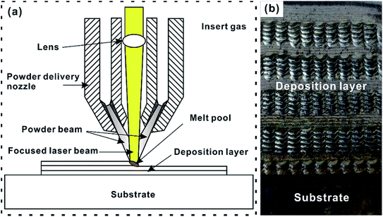 | ||
| Fig. 1 DLD process and specimens preparation. (a) Schematic diagram of DLD process; (b) deposition strategy. | ||
| Parameter | Value |
|---|---|
| Laser spot diameter (mm) | 5 |
| Laser power (kW) | 1.8 |
| Laser scanning speed (m s−1) | 0.1 |
| Feeding gas flow (L min−1) | 4 |
| Protective gas flow (L min−1) | 20 |
| Overlap distance (mm) | 2 |
| Each layer rising height (mm) | 1 |
2.2. Interface bonding strength experiment
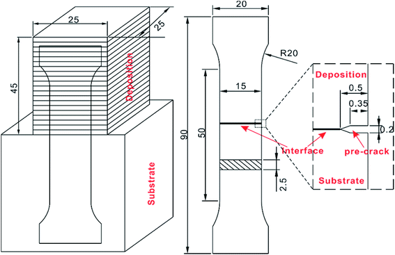
A pre-crack was fabricated at the interface edge by wire cutting machine to ensure that the initial crack propagated along the interface. The specific size was shown in Fig. 2. Half of specimens were post-heat treatment as control group. Their temperature would rise from room temperature to 850 °C with a speed of 10 °C min−1, keep 4 h and then cooled down to the room temperature in the furnace. INSTRON-5500R universal testing machine was used for uniaxial tensile experiments. Displacement loading method was adopted, and the value was 1 mm min−1. The experimental procedure strictly followed the ISO 6892-1 standard.2.3. Material characterization
A series of microstructural characterization, such as scanning electron microscope (SEM, JSM-IT300), field emission scanning electron microscopy (FE-SEM, JEM-7500F) with an energy dispersion spectroscope (EDS), electron probe micro-analyzer (EP, JXA-8230) and rotation anode high power X-ray diffractometer (XRD, D/MAX-RB), had been used to analyse. The actual thermal expansion coefficient of the In625 deposition and AISI 1045 substrate were measured by thermal expansion instrument (DIL402C).3. Results and discussion
3.1. Mechanical analysis
The displacement–load curves were in Fig. 3a. The black curve represented the original specimen, while the red curve represented the post-heat treatment specimen. Because the elastic modulus of In625 was different from that of 1045 substrate, there was no obvious linear elastic stage. The ultimate load of both specimens exceeded the yield strength (σs) of AISI 1045 steel. It can be concluded that plastic deformation occurs in both the substrate and deposition. The composite without post-heat treatment shew better mechanical properties. Each group of specimens was repeated five times, and the statistical data were in Fig. 3b.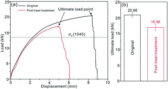 | ||
| Fig. 3 Tensile experiment data. (a) Displacement–load curves of two composites; (b) statistical results of average ultimate load. | ||
The average normal stress (σ = P/A) of two composites was 556.8 MPa and 452.3 MPa respectively. Its ultimate tensile strength was reduced by nearly 20%. Due to the existence of pre-crack, tensile fracture initial propagated along the interface in Fig. 4a. Once the normal stress reached the critical value, the front of the pre-crack began to crack and propagated along the bonding interface. With loading, the crack propagated along the interface rapidly, resulting in steep drop of displacement–load curve. This critical value could be defined as the interfacial bonding strength of composites. In terms of crack propagation path, the original specimen was always along the interface. For post-heat treatment, due to the uneven local plastic deformation, the crack deflected toward 1045 substrate side (relatively weak material side) at the end of interface in Fig. 4b. From the actual results, post-heat treatment did lead to a decrease in interfacial bonding strength.
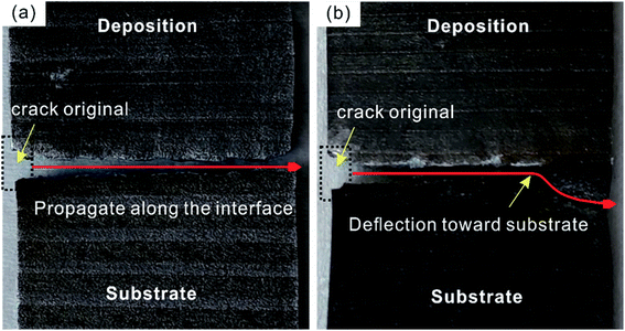 | ||
| Fig. 4 Macroscopic tensile fracture section. (a) Original specimen; (b) post-heat treatment specimen. | ||
The effect of post-heat treatment is embodied in the removal of residual stress and phase transformation of microstructures. Residual stress will inevitably occur at the bonding interface due to the different thermos-physical parameters of heterogeneous materials. Usually, thermal residual stress has an adverse effect on the mechanical properties of components. However, the uniaxial tensile experiment data conflicted with the general situation. In thermal processes, residual stresses mainly arise from two sources: (i) phase transformation shrinkage of In625 powder particles after solidification and (ii) differences of thermal expansion coefficient between In625 deposition and 1045 substrate. The thermal expansion coefficients of the two materials were measured from room temperature to 600 °C. The thermal expansion coefficient of In625 deposition (αd = 14.7) was less than that of 1045 substrate (αs = 15.6). And the main physical parameters of In625 and 1045 were shown in Table 2.
DLD process produced non-uniform temperature field, which was characterized by high temperature in the middle of deposition and low temperature on both sides. When the heating temperature was too high, large internal deformation would occur in the central part of the deposition, which leaded to plastic deformation when the thermal strain exceeded the yield strength. Once restored to room temperature, residual deformation would form a residual stress, in which the center was tensioned and the sides were compressed. The thermal expansion coefficient of 1045 substrate was larger than that of In625 deposition, causing the bonding residual stress near the interface edge was compressive. This part of residual stress was beneficial to tensile strength. After post-heat treatment, these compressive residual stresses were released, which resulted in the decrease of interfacial bonding strength.
3.2. Fractography and metallographic analysis
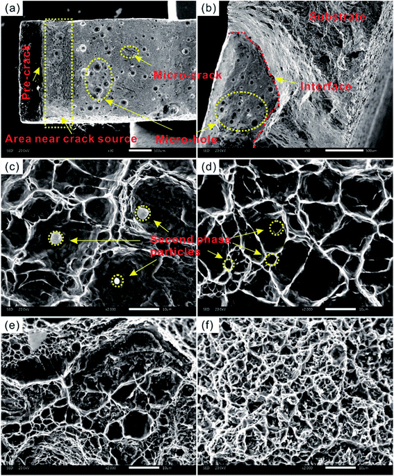
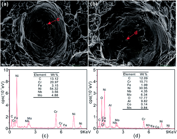
Macroscopic fracture morphology of tensile specimens was dark and fibrous in Fig. 5a (original specimen near the pre-crack (×30)) and Fig. 5b (post-heat specimen at crack deflection location (×50)), there were many holes and cracks visible to the naked eye. In the DLD processing, some micro-pores and thermal cracks were easily formed at the interface. Under the action of external force, stress concentration occurred in these defects, and accumulated until fracture. Microscopic fracture morphology was obvious equiaxed dimples in Fig. 5c and d (original specimen and post-heat specimen near the crack source (×2000)). The size of dimples was different, while the large dimples were surrounded by small dimples. The distribution of the second phase particles was similar to dimple distribution, showing a one-to-one correspondence feature. The second phase particles separated from the matrix can be found by observing the bottom of big dimples by high magnification in Fig. 5e and f (original specimen and post-heat specimen at the interface terminal (×2000)). It can deduce that these second phase particles were the core of forming dimples. The average dimple diameter of the original specimen was less than that of post-heat treatment. Many small dimples gathered around the large dimples. Because dislocations can accumulate on different slip planes, dislocations on other slip planes moved towards micro-voids to make them grew up. A large number of micro-voids accumulated under external force, while the matrix cross-section between adjacent micro-voids shrunk continuously, which leaded to fracture and dimples growth. By contrast, in the middle of fracture section, the dimples of original specimen were larger and flat, while the dimples after post-heat treatment were smaller conical.The formation mechanism of dimples is void accumulation, and the evolution process goes through nucleation, growth, accumulation and fracture. Most of the alloy voids are formed at the second phase particles, which can be found at the bottom of the dimples. Generally, cracks in alloys nucleated at the second phase particles or their interface with the matrix, then grew and propagated.23 By comparing the composition of the second phase particles at the bottom of dimples in Fig. 6, it was found that the oxygen content increased significantly after post-heat treatment. This would cause grain boundary segregation, reduced its effective surface energy, weakened grain boundary, and increased the risk of crack propagation along grain boundary. As shown in Fig. 6c and d, Nb as an additive can ensure strength by forming γ′′-Ni3Nb phase. Due to the segregation of Nb, a dense accumulation phase such as Laves phase will be formed. Laves phase is an intermetallic compound with A2B structure, where A = Fe/Ni/Cr, B = Nb/Mo/Si. When it forms in solid state, it usually causes strength loss and premature failure. In addition, Ni–Al formed γ′ precipitation strengthening phase. Only when the Al elements do not exceed the dissolution limit value in nickel-rich austenite phase can they become effective strengthening agents. After post-heat treatment, the Al content obviously exceeds the dissolution limit value (approximate to 7% at 1000 °C). The γ′ phase leads to aging shrinkage, which is the inducing factor of hot cracking.
3.3. Effect of post-heat treatment on microstructure at the interface
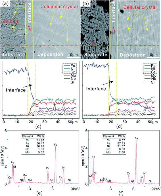
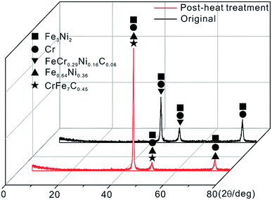
The grain morphology of In625 deposition near the interface and the composition of interfacial phase were analysed and compared. In Fig. 7a and b (microstructure of original specimen and post-heat specimen (×1000)), the left half was corroded AISI 1045 steel substrate, while the right half was In625 deposition. It can be seen that the interfacial phase was a bright white plane crystal band with a width of about 5 μm. The grain morphology of original specimen was columnar crystal, and the growth direction was perpendicular to the interface. After post-heat treatment, the grain morphology changed from columnar to cellular. The results of EDS line scanning along the red line were shown in Fig. 7c and d. The contents of Fe/Ni/Cr had obvious mutation at the interface, which were due to the melting and dilution of In625 and substrate in DLD process. The composition analysis of the selected two red points were in Fig. 7e and f. After post-heat treatment, the content of Cr/Ni/Mo elements decreased, except for the increased of iron. The reduction of solution strengthening element Cr in matrix caused will result in loss of strength. And decrease in Cr and Mo can promote the formation of M23C6 carbides. They have the potential to form orthorhombic intermetallic δ phase in the segregation region near the interface. The precipitation of M23C6 carbides and the brittle δ phase can potentially reduce the ductility and toughness of materials.By analysing the composition of second phase particles and interfacial phase, the phase transition did take place after post-heat treatment. To further determine the phase transition, the XRD analysis was in Fig. 8. We selected the first layer of deposition above the interface to ensure that XRD analysis was close to the interface phase. In625 was a solid solution strengthening alloy with austenite structure (FeCr0.29Ni0.16C0.06) with limited solubility to alloying elements. Austenite solution strengthening was carried out by Fe/Cr/Mo elements. In the face-centered cubic structure of Ni, the solution of Cr played a role in both solid solution and oxidation passivation, thus improving the corrosion resistance and high temperature oxidation resistance. Austenite solid-state phase transformation was occurred after post-heat treatment. The diffusion ability of carbon in Ni-rich γ-Fe was much lower than that of α-Fe. Carbon atoms were affected by the greater affinity of Cr, and chromium carbides were precipitated by diffusion and migration. These alloying elements interacted with Ni and Fe in the matrix to form eutectic with low melting point, segregated at grain boundary, and produced crystallization cracks under thermal stress. In the solidification processing, the undercooling at the bonding interface was relatively high, and the columnar austenite crystals with strong orientation will be formed. These low melting point eutectic segregated between columnar crystals. After post-heat treatment, the grain growth was obvious, which further promoted the formation of these eutectic. Therefore, crack sources were more likely to be generated under external force.
4. Conclusions
In this paper, Inconel 625/1045 were used to deposit composites by DLD process. The interfacial bonding strength of composites with/without post-heat treatment were compared by uniaxial tensile experiments. It was found that the interfacial bonding strength of original specimen (556.8 MPa) was stronger than that of post-heat treatment specimen (452.3 MPa). After post-heat treatment, the grains near the interface changed from columnar to cellular. The precipitation of chromium carbides and eutectic alloys at grain boundaries increased the risk of cracking. EDS of the second phase particles showed that the aluminum content exceeded its dissolution limit in nickel-rich austenite, which potentially increased the risk of thermal cracking. With the increase of oxygen content, the effective surface energy decreased and the grain boundary weakened. These changes indicated that post-heat treatment in In625/AISI 1045 composites could adversely affect interfacial bonding strength. The thermal expansion coefficient of In625 deposition (αd = 14.7) was less than that of 1045 substrate (αs = 15.6) in actual measurement. The compressive residual stress at the edge of interface will be generated during DLD process, which was beneficial to interfacial bonding strength. Residual stress releasing that caused by post-heat treatment will reduce the mechanical properties of composites. These results indicated that post-heat treatment process can be omitted for the repair application of nickel-based Inconel 625 alloy. It has important engineering value for improving repair efficiency. Moreover, it provides an idea of material matching, that is, this kind of material matching (αd < αs), is more suitable for remanufacturing field.Conflicts of interest
There are no conflicts to declare.Acknowledgements
This work was financially supported by the National Natural Science Foundation of China (No. 51210008, 51875425) and Fundamental Research Funds for the Central Universities (WUT: 2018IVA023).Notes and references
- R. Muñoz-Moreno, V. D. Divya, S. L. Driver, O. M. D. M. Messe, T. Illston, S. Baker, M. A. Carpenter and H. J. Stone, Mater. Sci. Eng., A, 2016, 674, 529–539 CrossRef.
- N. Shamsaei, A. Yadollahi, L. Bian and S. M. Thompson, Addit. Manuf., 2015, 8, 36–62 CrossRef.
- C. Sainan and G. Dongdong, J. Mater. Res., 2015, 30(23), 13 Search PubMed.
- J. Y. Jin and S. I. Hong, Mater. Sci. Eng., A, 2014, 596(3), 1–8 CrossRef CAS.
- B. E. Carroll, R. A. Otis, J. P. Borgonia, J. Suh, R. P. Dillon, A. A. Shapiro, D. C. Hofmann, Z. Liu and A. M. Beese, Acta Mater., 2016, 108, 46–54 CrossRef CAS.
- J. Chen, S. H. Wang and L. Xue, J. Mater. Sci., 2011, 47(2), 779–792 CrossRef.
- L. J. Kumar and C. G. K. Nair, Mater. Today: Proc., 2017, 4(10), 11068–11077 Search PubMed.
- G. Sun, R. Zhou, J. Lu and J. Mazumder, Acta Mater., 2015, 84, 172–189 CrossRef CAS.
- R. M. Molak, H. Araki, M. Watanabe, H. Katanoda, N. Ohno and S. Kuroda, J. Therm. Spray Technol., 2015, 24(8), 1459–1479 CrossRef CAS.
- A. Chaudhuri, Y. Raghupathy, D. Srinivasan, S. Suwas and C. Srivastava, Acta Mater., 2017, 129, 11–25 CrossRef CAS.
- N. Ahmed, K. T. Voisey and D. G. Mccartney, J. Therm. Spray Technol., 2014, 23(3), 402–409 CrossRef CAS.
- N. J. Harrison, I. Todd and K. Mumtaz, Acta Mater., 2015, 94, 59–68 CrossRef CAS.
- Y. Li, X. Cui, G. Jin, Z. Cai, N. Tan, B. Lu and Z. Gao, Mater. Des., 2017, 123, 54–63 CrossRef CAS.
- D. Tomus, T. Jarvis, X. Wu, J. Mei, P. Rometsch, E. Herny, J. F. Rideau and S. Vaillant, Phys. Procedia, 2013, 41(complete), 823–827 CrossRef.
- Y. Zhang, D. Sun, X. Gu and H. Li, Mater. Lett., 2016, 185, 152–155 CrossRef CAS.
- C. Godoy, E. A. Souza, M. M. Lima and J. C. A. Batista, Thin Solid Films, 2002, 420(02), 438–445 CrossRef.
- F. Ghadami, M. H. Sohi and S. Ghadami, Surf. Coat. Technol., 2015, 261, 289–294 CrossRef CAS.
- B. Al-Mangour, P. Vo, R. Mongrain, E. Irissou and S. Yue, J. Therm. Spray Technol., 2014, 23(4), 641–652 CrossRef CAS.
- X. Wu and Y. Hong, Mater. Sci. Eng., A, 2001, 318(1–2), 15–21 CrossRef.
- L. Lin, X. Wang and X. Zeng, Eng. Fract. Mech., 2017, 169, 276 CrossRef PubMed.
- X. C. Zhang, B. S. Xu, H. D. Wang and Y. X. Wu, Thin Solid Films, 2005, 488(1), 274–282 CrossRef CAS.
- Y. L. Hu, X. Lin, X. F. Lu, S. Y. Zhang, H. O. Yang, L. Wei and W. D. Huang, J. Mater. Sci., 2018, 1–17 Search PubMed.
- J. Yang, G. Z. Wang, F. Z. Xuan, S. T. Tu and C. J. Liu, Mater. Des., 2014, 53, 611–619 CrossRef CAS.
| This journal is © The Royal Society of Chemistry 2019 |

