 Open Access Article
Creative Commons Attribution 3.0 Unported Licence
A general method to fabricate MoO3/C composites and porous C for asymmetric solid-state supercapacitors†
Yu Jianga,
Xuemin Yan *a,
Yapeng Chenga,
Yan Zhanga,
Wei Xiaoa,
Lu Ganc and
Haolin Tang
 *b
*b
aCollege of Chemistry and Environmental Engineering, Yangtze University, Jingzhou 434023, Hubei, China. E-mail: XueminYan@126.com
bState Key Laboratory of Advanced Technology for Materials Synthesis and Processing, Wuhan University of Technology, Wuhan 430070, PR China. E-mail: thln@whut.edu.cn
cSchool of Foreign Studies, Yangtze University, Jingzhou 434023, Hubei, China
First published on 30th April 2019
Abstract
MoO3 is one of the most promising electrodes for high energy density supercapacitors due to its layered structure, which facilitates the insertion/removal of small ions. However, the commercial recognition of MoO3-based electrodes has been hampered by their low electronic conductivity, poor structural stability and narrow working potential window. A MoO3/C composite (MCs) has been synthesized by a polymerization method followed by calcination of the obtained hydrogel. The obtained MCs electrode exhibits remarkable electrochemical performance in both aqueous (432.5 F g−1 at a current density of 0.5 A g−1, 100% capacity retention after 10![[thin space (1/6-em)]](https://www.rsc.org/images/entities/char_2009.gif) 000 cycles) and all-solid (220.5 F g−1 at 0.5 A g−1) systems with porous C as the positive electrode, demonstrating its potential in commercial utilization.
000 cycles) and all-solid (220.5 F g−1 at 0.5 A g−1) systems with porous C as the positive electrode, demonstrating its potential in commercial utilization.
1. Introduction
Supercapacitors, a widely used class of energy storage devices, can perfectly bridge the performance gap between lithium ion batteries and conventional capacitors due to their advanced power density, cyclicity and excellent energy density.1,2 The development of supercapacitors has been spurred by the rising demand for more powerful energy devices, especially for emerging energy storage devices such as public transportation, hybrid electric vehicles, backup energy systems and consumer electronic devices. The energy density can be enhanced via increasing the specific capacitance (C) and the operation voltage (V) based on the equation: E = 1/2CV2.3,4 Therefore, considerable attention has been attracted by pseudo-capacitors due to their higher energy density than electrochemical double-layer capacitors resulting from their extraordinary storage mechanisms of charges, which undergo fast reversible faradaic reactions on the surface of the electrode materials.5MoO3 has been extensively explored as a supercapacitor electrode for the improvement of energy density due to its unique structure, which is composed of stacking bilayer sheets of MoO6 octahedra with van der Waals interactions to facilitate the insertion/extraction of ions.6,7 However, MoO3-based supercapacitors suffer from inadequate cycle life and limited practical capacitance due to their sluggish faradaic redox kinetics, low conductivity (10−5 S cm−1) and lack of structural integrity during cycling, especially at high rates in electrochemical devices.8,9 Combining MoO3 with a conductive material appears to be an effective way to address these capacitance attenuation problems; this can significantly improve the conductivity of MoO3-based electrodes and provide a firm framework for MoO3, facilitating maintenance of the structural integrity of the electrodes during cycling. For example, Shaheen and his co-workers reported that the specific capacitance of an rGO/MoO3@C composite electrode can reach 562 F g−1 at a current density of 1 A g−1.10 Rout et al. synthesized a MoO3/reduced graphene oxide composite material which can deliver a specific capacitance of 724 F g−1 at 1 A g−1 and which exhibits a superior capacitance retention of 50% even after 800 cycles.11 Shakir et al. synthesized hydrogenated molybdenum trioxide (HxMoO3) nanowires that yielded a specific capacitance of 168 F g−1 at 0.5 A g−1, with excellent capacitance retention of 97% after 3000 cycles.12 Wen et al. synthesized polypyrrole@MoO3/reductive graphite oxide nanocomposites which demonstrate favorable cycling behavior at a current density of 0.5 A g−1; the capacity loss was only 12% after 600 cycles.13 However, the energy density of MoO3-based electrodes is hindered by their narrow operation potential window, which is only about −1 to 0 V vs. Ag/AgCl in Na2SO4 aqueous solution due to decomposition of the aqueous electrolyte. Although using organic electrolyte is a feasible approach to enhance the potential window, poor safety and environmental toxicity undermine their application potential in supercapacitors.14–16 Therefore, neutral aqueous electrolytes (e.g., Na2SO4 and Li2SO4) are still promising electrolyte systems for the next generation of supercapacitors due to their advantages of no corrosion, environmental benignity and mass scale application.
Assembling asymmetric supercapacitors with positive electrodes provides a new cell configuration to increase the working potential window in aqueous electrolyte. Herein, we assembled an asymmetric supercapacitor using the MCs and porous carbon (PC) as a negative and positive electrode, respectively. For the negative electrode, a high surface area for faradaic reactions can be formed due to the deposition of MoO3 nanoparticles on the surface of the C substrate. The strong oxygen bonding between the MoO3 nanoparticles and carbon facilitates interfacial charge transfer and prevents the collapse of the nanostructures. For the positive electrode, the porous structure decreases the diffusion path for both ions and electrons, enhancing the rate performance of the electrode. Furthermore, considering environmental friendliness and safety, a Na2SO4/PVP gel was used as the electrolyte. Based on the working potential window of the MCs and the PC, the voltage range of the hybrid ASCs should be much wider than that of symmetric cells based on the MCs or PC. The specific capacitance of a single electrode in the ASCs can reach 220.5 F g−1 at 0.5 A g−1, certifying its outstanding electrochemical performance. Building on these data, it is reasonable to speculate that these ASCs, which can be fabricated via a simple procedure, hold great promise as alternative devices in energy storage applications.
2. Experimental
2.1. Chemicals and regents
Acrylamide, N,N′-methylenebisacrylamide, ammonium persulfate, phosphomolybdic acid hydrate, and ammonium hydroxide were obtained from Sinopharm Chemical Reagent Co., Ltd. No purification was performed on these chemicals before use. The resistance of the deionized (DI) water used in the reactions is 18.2 MΩ cm−1.2.2. Preparation of MCs
For synthesis of the MCs, 5 g of acrylamide, 3.5 g of phosphomolybdic acid hydrate, 0.2 mL of ammonium hydroxide and 0.01 g of N,N′-methylenebisacrylamide were mixed in 15 mL DI water under vigorous stirring. After a homogeneous solution was formed, 5 mL of ammonium persulfate (4 mg mL−1) was added slowly, followed by curing at 75 °C for 5 min. The obtained hydrogel was calcinated at 650 °C for 2 h under argon after drying in a lyophilizer.PC was synthesized through a similar synthetic procedure without addition of phosphomolybdic acid hydrate or ammonium hydroxide.
2.3. Characterization
The morphological details of the as-prepared samples were examined using a scanning electron microscope (SEM, Merlin, GER) at an acceleration voltage of 10.0 kV and a transmission electron microscope (TEM, a JEM-2100HR, JPN) at an acceleration voltage of 200 kV. X-ray photoelectron spectra (XPS) of the samples were obtained using an Al Kα X-ray source (1486 eV). Raman spectra were measured using a confocal LabRAM HR800 spectrometer with an excitation wavelength of 514 nm provided by an argon ion laser.2.4. Electrochemical measurements
To prepare the working electrodes, the MCs (80%) or PC (80%), acetylene (10%) and polytetrafluoroethylene (10%) were mixed to form a slurry, which was dip-coated onto a carbon paper with an area of ∼1 cm2. After that, the obtained carbon paper was dried at 80 °C under vacuum (the mass loadings of MCs and PC were ∼1.0 mg and ∼4.8 mg, respectively). In the three-electrode configuration, the electrochemical performance of the MCs or PC was tested in 1.0 M Na2SO4 aqueous electrolyte with Ag/AgCl as a reference electrode and Pt mesh as a counter electrode. The ASC was assembled using the MCs as a positive electrode, the PC as a negative electrode, PVP/Na2SO4 gel as the electrolyte, which was prepared by mixing 4 g PVP (K30) and 3 g Na2SO4 in 40 mL DI water at 90 °C with 4 h of vigorous stirring, and fibrous paper as a separator. All electrochemical tests were carried out using a CHI 660E workstation (Shanghai Chenghua).3. Results and discussion
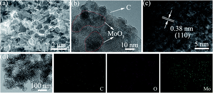
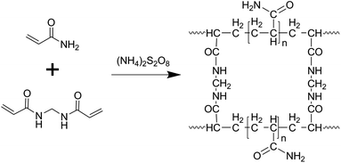
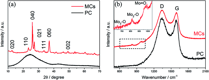
The morphology of the MCs is shown in Fig. 1a and b; a 3D structure with a smooth surface can be clearly observed, illustrating that the MoO3 nanoparticles were uniformly distributed on the surface of C. The formation of the 3-dimensional porous structure may be due to the polymerization of acrylamide and N,N′-methylenebisacrylamide (as shown in the polymerization reaction in Scheme 1). The addition of ammonium hydroxide can improve the solubility of phosphomolybdic acid hydrate in aqueous solution contained in the polymer matrix, which facilitates the even distribution of MoO3 in the C substrate after calcination. The existence of MoO3 can also be certified by HRTEM (Fig. 1c), in which well-defined lattice fringes with an interplanar spacing of 0.38 nm can be observed, matching the (110) planes of MoO3.17,18 Furthermore, element mapping analysis of Fig. 1d shows an even spatial distribution of C, O and Mo elements, which is consistent with the aforementioned measurements.The XRD pattern of the MCs is shown in Fig. 2a; all of the diffraction peaks can be readily indexed to α-MoO3 (JCPDS file no. 05-0508) with no impurities detected, suggesting high purity of the MCs.19,20 For the PC, only a hump diffraction peak can be observed at around 24.5°, which is ascribed to the graphite (002) plane; this results from the carbonization of the hydrogel.21,22 Note that the presence of MoO3 can also be identified by the Raman spectra in Fig. 2b; the Raman bands at around 995 cm−1, 818 cm−1 and 665 cm−1 are assigned to the Mo![[double bond, length as m-dash]](https://www.rsc.org/images/entities/char_e001.gif) O and Mo3–O stretching modes, respectively.23,24 The appearance of two prominent peaks in the Raman spectrum correspond to the characteristic G (associated with the E2g phonons of C sp2 atoms) and D (arising from the mode of the k point phonons with A1g symmetry) bands of the graphitic structure.25,26 The thermogravimetric analysis (TGA) curve shows that the hydrogel undergoes significant decomposition when heated to 800 °C under nitrogen flow, exhibiting a three-step degradation process, as indicated in Fig. S1.† The mass loss (∼2 wt%) below 150 °C can be attributed to removal of adsorbed water, and the mass loss (∼52 wt%) at 150 °C to 400 °C and 400 °C to 800 °C can be assigned to pyrolysis of oxygen functional groups and decomposition of phosphomolybdic acid hydrate.
O and Mo3–O stretching modes, respectively.23,24 The appearance of two prominent peaks in the Raman spectrum correspond to the characteristic G (associated with the E2g phonons of C sp2 atoms) and D (arising from the mode of the k point phonons with A1g symmetry) bands of the graphitic structure.25,26 The thermogravimetric analysis (TGA) curve shows that the hydrogel undergoes significant decomposition when heated to 800 °C under nitrogen flow, exhibiting a three-step degradation process, as indicated in Fig. S1.† The mass loss (∼2 wt%) below 150 °C can be attributed to removal of adsorbed water, and the mass loss (∼52 wt%) at 150 °C to 400 °C and 400 °C to 800 °C can be assigned to pyrolysis of oxygen functional groups and decomposition of phosphomolybdic acid hydrate.
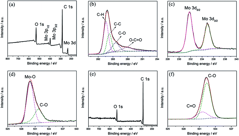
High-resolution XPS measurements were applied to characterize the chemical valence states of Mo, O and C. As shown in Fig. 3a, Mo, C and O are the only elements that can be recognized in the survey spectrum of the MCs. The deconvolution of C 1s in Fig. 3b implies the presence of four different components with binding energies of 283.8, 284.6, 285.8 and 287.9 eV, corresponding to C–H, C–C, C–O and O–C![[double bond, length as m-dash]](https://www.rsc.org/images/entities/char_e001.gif) O, respectively.27,28 This implies the existence of oxygenated functional groups in the C nanoparticles, which facilitates the deposition of MoO3 nanoparticles on the surface of the C substrate. In the spectrum of the Mo 3d region in Fig. 3c, a doublet can be identified at binding energies of 232.5 eV and 235.6 eV; these are attributed to Mo(VI) 3d5/2 and 3d3/2, demonstrating the formation of MoO3.29,30 Fig. 3d shows the spectral deconvolution of O 1s, which consists of two different components; the peak at 532.6 eV can be assigned to C–O of the C substrate, while the peak at 530.2 eV can be attributed to Mo–O in MoO3. The survey spectrum of the PC is shown in Fig. 3e; only C and O can be identified. As shown in Fig. 3f, two peaks at banding energies of around 531.5 and 532.4 eV can be confirmed in the spectral deconvolution of O 1s, corresponding to C
O, respectively.27,28 This implies the existence of oxygenated functional groups in the C nanoparticles, which facilitates the deposition of MoO3 nanoparticles on the surface of the C substrate. In the spectrum of the Mo 3d region in Fig. 3c, a doublet can be identified at binding energies of 232.5 eV and 235.6 eV; these are attributed to Mo(VI) 3d5/2 and 3d3/2, demonstrating the formation of MoO3.29,30 Fig. 3d shows the spectral deconvolution of O 1s, which consists of two different components; the peak at 532.6 eV can be assigned to C–O of the C substrate, while the peak at 530.2 eV can be attributed to Mo–O in MoO3. The survey spectrum of the PC is shown in Fig. 3e; only C and O can be identified. As shown in Fig. 3f, two peaks at banding energies of around 531.5 and 532.4 eV can be confirmed in the spectral deconvolution of O 1s, corresponding to C![[double bond, length as m-dash]](https://www.rsc.org/images/entities/char_e001.gif) O and C–O of the C substrate, respectively.24,31,32 These comparisons imply the formation of C–O–Mo in the MCs.
O and C–O of the C substrate, respectively.24,31,32 These comparisons imply the formation of C–O–Mo in the MCs.
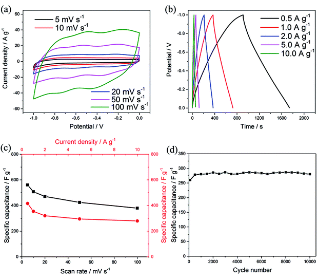
To evaluate the electrochemical performance of the MCs as an electrode for supercapacitors, cyclic voltammetry (CV) and galvanostatic charge–discharge (GCD) tests were performed in aqueous 1 M Na2SO4 electrolyte using a three-electrode system. Typical CV curves can be observed at a scan rate of 5–100 mV s−1 within a potential window of −1 to 0 V, as shown in Fig. 4a; two pairs of redox peaks can be observed at −0.21/−0.34 and −0.54/−0.68, attributed to the reversible and fast insertion/extraction of Na+ into/out of the MoO3 phase, suggesting pseudocapacitance behavior.6,8,33 The current response was enhanced with increasing scan rate and showed no obvious shift at the positions of the redox peaks, which is consistent with fast electron-transfer kinetics. Meanwhile, all the GCD curves presented relatively symmetric shapes with varied current densities from 0.5 A g−1 to 10 A g−1 (Fig. 4b). The specific capacitance C (F g−1) for a single electrode was calculated from the CV and GCD results by eqn (1) and (2), respectively:34,35
 | (1) |
 | (2) |
![[thin space (1/6-em)]](https://www.rsc.org/images/entities/char_2009.gif) 000 charge–discharge cycles (as shown in Fig. 4d); this indicates fast ion diffusion and excellent electronic transport, which originate from the unique 3D structure of the MCs. The C substrate in the MCs serves dual functions as both a framework to maintain the structural integrity of MoO3 and as conductive channels to improve the charge transfer kinetics during cycling.
000 charge–discharge cycles (as shown in Fig. 4d); this indicates fast ion diffusion and excellent electronic transport, which originate from the unique 3D structure of the MCs. The C substrate in the MCs serves dual functions as both a framework to maintain the structural integrity of MoO3 and as conductive channels to improve the charge transfer kinetics during cycling.
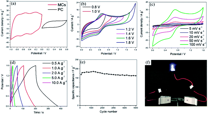
To evaluate the electrochemical performance of the MCs in a practical cell, an ASC was assembled using PC and the MCs as the positive and negative electrode, respectively. In order to explore the stable potential windows and balance the capacity of the MCs-based electrode and PC-based electrode, CV measurements of each material were performed in 1 M Na2SO4 aqueous solution at a scan rate of 50 mV s−1, as shown in Fig. 5a. The PC-based electrode was measured within a potential window of 0 to 0.8 V (Ag/AgCl); it exhibited typical double-layer characteristics, which afford superior cycling performance, as shown in Fig. S5.† Meanwhile, the MCs-based electrode was measured within a potential window of −1 to 0 V (Ag/AgCl). Because the total cell voltage is the sum of the potential ranges of the positive and negative electrodes, the asymmetric cell can be operated within a potential window of 0 to 1.8 V. The specific capacitances calculated from the CV curves were 424.2 F g−1 for the MCs-based electrode and 110.3 F g−1 for the PC-based electrode. In order to balance the charges of the positive electrode and negative electrode, the optimized mass ratio of the negative electrode/positive electrode should be 0.21 in the cell, based on the equation: Q = C × V × m.36
CV curves of the ASC in different potential windows (from 0 to 0.8 and 0 to 1.8 V) were measured at a scan rate of 50 mV s−1, as shown in Fig. 5b. The distorted rectangular shapes of the CVs in different ranges of potential indicate that the capacitance of the asymmetric cell is derived from a combination of pseudocapacitance and electrochemical double layer capacitance. Moreover, no obvious irreversible current can be observed in the CV curves, even when the potential window was increased to 1.6 V; this indicates that stable performance can be achieved in this wide potential window during cycling. To assess the electrochemical performance of the ASC, CV and GCD measurements were employed, as shown in Fig. 5c and d. The current response increased with increasing scan rate in the CV curves and showed no obvious shape changes, which demonstrates the superior electron-transfer kinetics of the ASCs. The specific capacitance of one electrode in the ASCs has been evaluated from the GCD curves according to the following equation: C = 4IΔt/mΔV,36,37 where I is the applied discharge current, Δt is the discharging time, m is the total mass of the positive and negative electrodes and ΔV is the potential window. A specific capacitance of 220.5 F g−1 was obtained at a current density of 0.5 A g−1, attributed to the superior electrochemical performance of both the positive and negative electrodes (which is also demonstrated by the Ragone plot in Fig. S6†). The cycling stability was evaluated between 0 and 1.6 V at a current density of 2 A g−1, as shown in Fig. 5e, in which the capacitance of the ASC exhibited only a slight decrease even after 5000 cycles. As shown in Fig. 5f, the ASCs were connected to a white LED to demonstrate the possibility of practical usage, and the LED could be easily lit.
4. Conclusions
In summary, a porous MCs-based electrode for supercapacitors has been fabricated by a simple and cost-efficient method. The MCs-based electrode exhibits remarkable electrochemical performance (432.5 F g−1 at a current density of 0.5 A g−1 and about 100% capacity retention after 10![[thin space (1/6-em)]](https://www.rsc.org/images/entities/char_2009.gif) 000 cycles), which is ascribed to the 3D interconnected structure and the strong interaction between MoO3 and the C substrate, which facilitates good accessibility of the electrode to the electrolyte and provides rapid and shorter diffusion paths for ions. Furthermore, an ASC has been assembled using the MCs-based electrode as the anode and the PC-based electrode as the cathode; it shows a high specific capacitance of 220.5 F g−1 at 0.5 A g−1 and good capacity retention, certifying the excellent potential of the electrode for all-solid-state supercapacitors.
000 cycles), which is ascribed to the 3D interconnected structure and the strong interaction between MoO3 and the C substrate, which facilitates good accessibility of the electrode to the electrolyte and provides rapid and shorter diffusion paths for ions. Furthermore, an ASC has been assembled using the MCs-based electrode as the anode and the PC-based electrode as the cathode; it shows a high specific capacitance of 220.5 F g−1 at 0.5 A g−1 and good capacity retention, certifying the excellent potential of the electrode for all-solid-state supercapacitors.
Conflicts of interest
There are no conflicts to declare.Acknowledgements
This work was financially supported by the National Science Foundation of China (51472034 and 51404038) and the Science and Technology Capability Innovation Project (Q20181318).References
- Y. Han, Z. Lai, Z. Wang, M. Yu, Y. Tong and X. Lu, Chem.–Eur J., 2018, 24, 7312–7329 CrossRef CAS PubMed.
- J. Zou, M. Zhang, J. Huang, J. Bian, Y. Jie, M. Willander, X. Cao, N. Wang and Z. L. Wang, Adv. Energy Mater., 2018, 8, 1702671 CrossRef.
- Y. N. Hou, Z. Zhao, Z. Yu, S. Zhang, S. Li, J. Yang, H. Zhang, C. Liu, Z. Wang and J. Qiu, Chem.–Eur J., 2018, 24, 2681–2686 CrossRef CAS PubMed.
- V. Strauss, K. Marsh, M. D. Kowal, M. El-Kady and R. B. Kaner, Adv. Mater., 2018, 30, 1704449 CrossRef PubMed.
- W. Wang, N. Zhang, Z. Shi, Z. Ye, Q. Gao, M. Zhi and Z. Hong, Chem. Eng. J., 2018, 338, 55–61 CrossRef CAS.
- J. Chen, S. Han, H. Zhao, J. Bai, L. Wang, G. Sun, Z. Zhang, X. Pan, J. Zhou and E. Xie, Chem. Eng. J., 2017, 320, 34–42 CrossRef CAS.
- H. S. Kim, J. B. Cook, H. Lin, J. S. Ko, S. H. Tolbert, V. Ozolins and B. Dunn, Nat. Mater., 2017, 16, 454–460 CrossRef CAS PubMed.
- D. Ruan, R. Lin, K. Jiang, X. Yu, Y. Zhu, Y. Fu, Z. Wang, H. Yan and W. Mai, ACS Appl. Mater. Interfaces, 2017, 9, 29699–29706 CrossRef CAS PubMed.
- S.-W. Zhang, B.-S. Yin, C. Liu, Z.-B. Wang and D.-M. Gu, Chem. Eng. J., 2017, 312, 296–305 CrossRef CAS.
- W. Shaheen, M. F. Warsi, M. Shahid, M. A. Khan, M. Asghar, Z. Ali, M. Sarfraz, H. Anwar, M. Nadeem and I. Shakir, Electrochim. Acta, 2016, 219, 330–338 CrossRef CAS.
- A. Pathak, A. S. Gangan, S. Ratha, B. Chakraborty and C. S. Rout, J. Phys. Chem. C, 2017, 121, 18992–19001 CrossRef CAS.
- I. Shakir, M. Shahid, U. A. Rana and M. F. Warsi, RSC Adv., 2014, 4, 8741 RSC.
- F. Yu, Y. Liu, Y. Zhu, F. Dai, L. Zhang and Z. Wen, Mater. Lett., 2016, 171, 104–107 CrossRef CAS.
- J. Noh, C.-M. Yoon, Y. K. Kim and J. Jang, Carbon, 2017, 116, 470–478 CrossRef CAS.
- P. Du, W. Wei, D. Liu, H. Kang, C. Liu and P. Liu, J. Mater. Sci., 2018, 53, 5255–5269 CrossRef CAS.
- C. Qu, B. Zhao, Y. Jiao, D. Chen, S. Dai, B. M. Deglee, Y. Chen, K. S. Walton, R. Zou and M. Liu, ACS Energy Lett., 2017, 2, 1263–1269 CrossRef CAS.
- X. Xiao, T. Ding, L. Yuan, Y. Shen, Q. Zhong, X. Zhang, Y. Cao, B. Hu, T. Zhai and L. Gong, Adv. Energy Mater., 2012, 2, 1328–1332 CrossRef CAS.
- K. Zhou, W. Zhou, X. Liu, Y. Sang, S. Ji, W. Li, J. Lu, L. Li, W. Niu, H. Liu and S. Chen, Nano Energy, 2015, 12, 510–520 CrossRef CAS.
- X. Cao, B. Zheng, W. Shi, J. Yang, Z. Fan, Z. Luo, X. Rui, B. Chen, Q. Yan and H. Zhang, Adv. Mater., 2015, 27, 4695–4701 CrossRef CAS PubMed.
- X. Zhang, X. Zeng, M. Yang and Y. Qi, ACS Appl. Mater. Interfaces, 2014, 6, 1125–1130 CrossRef CAS PubMed.
- P. M. Shafi, R. Dhanabal, A. Chithambararaj, S. Velmathi and A. C. Bose, ACS Sustainable Chem. Eng., 2017, 5, 4757–4770 CrossRef CAS.
- F. N. I. Sari and J.-M. Ting, ChemSusChem, 2018, 11, 897–906 CrossRef CAS PubMed.
- R. Kumar, N. Goel, M. Mishra, G. Gupta, M. Fanetti, M. Valant and M. Kumar, Adv. Mater. Interfaces, 2018, 1800071 CrossRef.
- B. Y. Zhang, A. Zavabeti, A. F. Chrimes, F. Haque, L. A. O'Dell, H. Khan, N. Syed, R. Datta, Y. Wang and A. S. Chesman, Adv. Funct. Mater., 2018, 28, 1706006 CrossRef.
- Y. Jiang, X. Yan, W. Xiao, M. Tian, L. Gao, D. Qu and H. Tang, J. Alloys Compd., 2017, 710, 114–120 CrossRef CAS.
- C. Chen, N. Hayazawa and S. Kawata, Nat. Commun., 2014, 5, 3312 CrossRef PubMed.
- Y. Jiang, Z.-J. Jiang, L. Yang, S. Cheng and M. Liu, J. Mater. Chem. A, 2015, 3, 11847–11856 RSC.
- J. Briscoe, A. Marinovic, M. Sevilla, S. Dunn and M. Titirici, Angew. Chem., Int. Ed., 2015, 54, 4463–4468 CrossRef CAS PubMed.
- L. B. Huang, L. Zhao, Y. Zhang, Y. Y. Chen, Q. H. Zhang, H. Luo, X. Zhang, T. Tang, L. Gu and J. S. Hu, Adv. Energy Mater., 2018, 1800734 CrossRef.
- M. Muneer, U. Alam, D. B. W. D. Bahnemann, J. Koch and C. Tegenkamp, Phys. Chem. Chem. Phys., 2018, 20, 4538–4545 RSC.
- J. Swiatowska-Mrowiecka, S. de Diesbach, V. Maurice, S. Zanna, L. Klein, E. Briand, I. Vickridge and P. Marcus, J. Phys. Chem. C, 2008, 112, 11050–11058 CrossRef CAS.
- B. M. Reddy, B. Chowdhury and P. G. Smirniotis, Appl. Catal., A, 2001, 219, 53–60 CrossRef CAS.
- W. Pan, R. Tian, H. Jin, Y. Guo, L. Zhang, X. Wu, L. Zhang, Z. Han, G. Liu and J. Li, Chem. Mater., 2010, 22, 6202–6208 CrossRef CAS.
- D. V. Pham, R. A. Patil, C.-C. Yang, W.-C. Yeh, Y. Liou and Y.-R. Ma, Nano Energy, 2018, 47, 105–114 CrossRef CAS.
- M. Zhang, K. Chen, C. Wang, M. Jian, Z. Yin, Z. Liu, G. Hong, Z. Liu and Y. Zhang, Small, 2018, 14, 1801009 CrossRef PubMed.
- J. Chang, M. Jin, F. Yao, T. H. Kim, V. T. Le, H. Yue, F. Gunes, B. Li, A. Ghosh, S. Xie and Y. H. Lee, Adv. Funct. Mater., 2013, 23, 5074–5083 CrossRef CAS.
- P. Song, X. Shen, W. He, L. Kong, X. He, Z. Ji, A. Yuan, G. Zhu and N. Li, J. Mater. Sci.: Mater. Electron., 2018, 29, 12206–12215 CrossRef CAS.
Footnote |
| † Electronic supplementary information (ESI) available. See DOI: 10.1039/c8ra10232e |
| This journal is © The Royal Society of Chemistry 2019 |

