 Open Access Article
Creative Commons Attribution 3.0 Unported Licence
Enhanced catalytic degradation of amoxicillin with TiO2–Fe3O4 composites via a submerged magnetic separation membrane photocatalytic reactor (SMSMPR)
Qilong Lia,
Hui Kongb,
Rongrong Jiaa,
Jiahui Shaoa and
Yiliang He *a
*a
aSchool of Environmental Science and Engineering, Shanghai Jiao Tong University, 800 Dongchuan Rd, Shanghai 200240, China. E-mail: ylhe@sjtu.edu.cn; Tel: +86-021-54744008
bSchool of Naval Architecture, Ocean and Civil Engineering, Shanghai Jiao Tong University, Shanghai 200030, PR China
First published on 23rd April 2019
Abstract
A novel photo-Fenton catalytic system for the removal of organic pollutants was presented, including the use of photo-Fenton process and a submerged magnetic separation membrane photocatalytic reactor (SMSMPR). We synthesized TiO2–Fe3O4 composites as the photocatalyst and made full use of the magnetism of the photocatalyst to realize the recollection of the catalyst from the medium, which is critical to the commercialization of photocatalytic technology for wastewater treatment. The photo-Fenton performance of TiO2–Fe3O4 is evaluated with amoxicillin trihydrate (AMX) as a target pollutant. The results indicate that the TiO2–Fe3O4/H2O2 oxidation system shows efficient degradation of AMX. Fe3O4 could not only enhance the heterogeneous Fenton degradation of organic compounds but also allow the photocatalyst to be magnetically separated from treated water. After four reaction cycles, the TiO2–Fe3O4 composites still exhibit 85.2% removal efficiency of AMX and show excellent recovery properties. Accordingly, the SMSMPR with the TiO2–Fe3O4 composite is a promising way for removing organic pollutants.
1. Introduction
The penetration of pharmaceuticals into the environment has drawn considerable attention in recent years.1–3 Several effective alternative water treatment technologies have been considered in recent studies, including adsorption,4,5 membrane filtration,6–8 coagulation9 and advanced oxidation technologies.10–12 Photocatalytic environmental remediation has always been the research focus since the breakthrough of water splitting was covered by Fujishima and Honda in 1972.13,14 Various photocatalysts have been used in the photocatalysis process, among which titanium dioxide (TiO2) is the most widely studied and applied owing to its advantages of strong oxidizing ability, chemical stability, nontoxicity, low cost and high hydrophilicity.13,15 The photo-Fenton process is a typical combination of two kinds of advanced oxidation process (AOP) and shows high oxidative removal efficiency of organics because of the highly enhanced generation of reactive hydroxyl radicals (·OH).16–18 However, one of the major drawbacks, separation and recycling of catalyst particles from large quantities of water, needs further cost and restrains the practical application of photocatalytic process. Accordingly, many studies were trying to explore an economic way to get the catalysts back. The ternary magnetic composite of Fe3O4@TiO2/SiO2 was prepared and used to remove Rhodamine B from wastewater. Results indicated that the Fe3O4@TiO2/SiO2 showed high photocatalytic activity and most importantly, it was recyclable.19 Fan et al. coated Fe3O4/SiO2 magnetic core with titania using hydrothermal synthetic method. With external magnetic field, the Fe3O4/SiO2/TiO2 magnetic nanocomposites could be separated from the suspension successfully. TiO2 decorated with Fe3O4 could generate greater photocatalytic activity as Fe3+ can occupy both of the electron capture position and hole capture position, resulting in the decrease of electron–hole pair recombination of TiO2. However, aggregation of TiO2 particles can influence the optical properties and photoactivity of catalyst,20 meaning the necessary of preventing the particles from aggregation during the photocatalysis process.Herein, we developed a special combination of TiO2–Fe3O4 catalysts, photo-Fenton process and SMSMPR. The incorporation of Fe3O4 can improve the catalytic activity of TiO2 (based on the energy level theory), and endowed TiO2 with excellent reusability with the help of external magnetic field.19 The two associated oxidation process, photocatalysis and Fenton oxidation can ensure the degradation of organics in an efficient way. The well-designed submerged magnetic separation membrane photocatalytic reactor can realize the waste water treatment and the separation of catalyst. The aeration in the reactor during the photocatalysis process will alleviate the agglomeration of TiO2 particles, which is essential to guarantee the specific surface area of photocatalyst. Also, the built-in backwashing treatment inside the SMSMPR could enhance the self-purification ability of membranes. We also evaluated the main factors influencing the removal of organics, tried to find out the optimum reaction condition and explored the possibility of cyclic utilization of the reaction system.
2. Materials and methods
2.1 Chemicals
Ferric nitrate (Fe(NO3)3·9H2O) and ethylene glycol (EG) were purchased from Shanghai Macklin Biochemical Co., Ltd. TiO2 was obtained from Degussa AG, Germany. Amoxicillin trihydrate (99.5%, k AMX), hydrogen peroxide (30%) and ethanol were supplied by Sinopharm Chemical Reagent Co., Ltd (Shanghai, China).2.2 Synthesis of TiO2–Fe3O4
TiO2–Fe3O4 particles were synthesized by a facile hydrothermal synthetic method.21 Firstly, 200 mL mixture of ethanol and water (v:v = 1![[thin space (1/6-em)]](https://www.rsc.org/images/entities/char_2009.gif) :
:![[thin space (1/6-em)]](https://www.rsc.org/images/entities/char_2009.gif) 1) was prepared. And different amounts of TiO2 and 5 mM Fe(NO3)3·9H2O were distributed in above solution by ultrasonic treatment for 3 h. Then it was dried at 60 °C, ground to powder and placed into a beaker, which was put in a 500 mL Teflon-lined autoclave. 60 mL ammonia solution was added into the autoclave beforehand and then sealed after the beaker was introduced. A drying oven was used to maintain a constant temperature for alkaline treatment in autoclave (180 °C for 12 h). Afterwards, the obtained samples were annealed at 200 °C for 5 h and the obtained powder was distributed in 100 mL EG by ultrasonic treatment for 3 h, after which the mixture was transferred to a 500 mL Teflon-lined autoclave and maintained at 180 °C for another 12 h. Finally, the obtained precipitates were washed three times with ethanol and distilled water and dried at 60 °C in vacuum. The final as-prepared products contained 10, 15, 20 and 25 wt% Fe3O4, respectively.
1) was prepared. And different amounts of TiO2 and 5 mM Fe(NO3)3·9H2O were distributed in above solution by ultrasonic treatment for 3 h. Then it was dried at 60 °C, ground to powder and placed into a beaker, which was put in a 500 mL Teflon-lined autoclave. 60 mL ammonia solution was added into the autoclave beforehand and then sealed after the beaker was introduced. A drying oven was used to maintain a constant temperature for alkaline treatment in autoclave (180 °C for 12 h). Afterwards, the obtained samples were annealed at 200 °C for 5 h and the obtained powder was distributed in 100 mL EG by ultrasonic treatment for 3 h, after which the mixture was transferred to a 500 mL Teflon-lined autoclave and maintained at 180 °C for another 12 h. Finally, the obtained precipitates were washed three times with ethanol and distilled water and dried at 60 °C in vacuum. The final as-prepared products contained 10, 15, 20 and 25 wt% Fe3O4, respectively.
2.3 Characterization
Scanning electronic microscope (SEM, JSM 7800F), transmission electron microscope (TEM) and high resolution transmission electron microscope (HRTEM, JEM-2100F) images were obtained to characterize the morphological features of samples. X-ray diffraction (XRD) was carried out using a Bruker D8 Advance X-ray diffractometer with Cu-Kα radiation over a scan rate of 10° min−1 in the 2θ range from 5° to 80°. A Tensor 27 Fourier-transform infrared spectroscopy (FTIR) spectrometer (Nicolet 6700) was used to record the FTIR spectra of catalyst. X-ray photoelectron spectroscopy (XPS) analysis (PerkinElmer PHI 5000C, AlKα) of TiO2–Fe3O4 nanocomposites was also performed.2.4 Photo-Fenton performance using SMSMPR
The photo-Fenton process was performed with the SMSMPR and a schematic illustration of the SMSMPR for organic contaminant removal was depicted in Fig. 1. In this study, AMX (30 mg L−1) was chosen as the model organic contaminant. The concentration of AMX was measured by the total organic carbon (TOC) using a total organic carbon analyzer (multi 3100, Analytik Jena, Germany). Firstly, a peristaltic pump was utilized to pump AMX from the feed tank into an stainless steel container (L × W × H = 200 mm × 200 mm × 500 mm) at a flow rate of 100 mL min−1, which accommodated low-pressure mercury lamps (TUV, Philips), perforated aeration pipes, the hollow ceramic membranes (150 mm in length, 120 mm in width, and 4 mm in thickness), a powerful magnet connected to an iron rod and the mixture of organic solution and catalyst. Low-pressure mercury lamps (LPML; Philips) were placed around the ceramic membrane for photocatalysis and the light intensity quantitatively of a 100 W LPML was 1200 mW cm−2. The perforated aeration pipes, connected to an air compressor, was placed at the bottom of the reactor to produce dissolved oxygen-rich micro-porous bubbles, which can keep the catalyst from gathering and settling down to the bottom. After the wastewater was successfully pumped into the reactor, the catalyst was dosed in and the air compressor was opened to fluidize the catalysts. The low-pressure mercury lamps were switched on and the photocatalysis began after 45 min, during which time the pharmaceutical solution and catalyst can be well-mixed and reach the equilibrium. As for the ceramic membranes, they were used for the separation of effluents from the catalyst slurry. After the photo-Fenton process finished, another peristaltic pump was used to pump the effluent out. Furthermore, the ceramic membranes were connected to the air compressor and can be used for backwashing, making the cyclic utilization of the system possible. Finally, an external magnetic field, provided by a powerful magnet connected to an iron rod was also employed to realize the recollection of catalysts.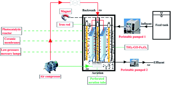 | ||
| Fig. 1 Schematic illustration of the submerged magnetic separation membrane photocatalytic reactor (SMSMPR). | ||
3. Results and discussion
Microimages of chemicals can provide its visual and intuitive morphology. The morphologies of photocatalysts were evaluated by SEM and TEM, and the corresponding images are presented in Fig. 2. Based on Fig. 2a and c, pure TiO2 had irregularly spherical shape with average diameter of 40 nm and the TiO2 particles were uniformly distributed in the plane. After combined with Fe3O4 (Fig. 2b and d), the nanoparticles showed obvious aggregation effect and smaller dimension, representing the presence of Fe3O4 in the composites and interaction between TiO2 and Fe3O4. Actually, during the formation of TiO2/Fe3O4 composites, the positively charged Fe3+ and negatively charged TiO2 can be attracted by each other and connected in the beginning. As the temperature becoming higher, the evaporated ammonia reacted with Fe3+ to produce Fe(OH)3 on the surface of TiO2 and the Fe(OH)3 were in situ formed on TiO2. After the annealed treatment at 200 °C for 5 h, the obtained Fe(OH)3 was decomposed to Fe2O3. Afterwards, EG was used as a reductant and effectively reduce Fe2O3 to Fe3O4 nanoparticles during the further hydrothermal process. Then TiO2–Fe3O4 composite was obtained. Accordingly, the driving force for the formation of TiO2–Fe3O4 composite was attributed to the attraction between the positively charged Fe3+ on Fe3O4 and negatively charged defects on the TiO2 surface. Fig. 2e revealed the interplanar distance of 0.345 nm and 0.315 nm, corresponding to the anatase (101) and rutile (101) planes of TiO2, respectively. As for the lattice fringes of 0.252 nm, they were characteristic of (311) crystal planes of cubic Fe3O4.22,23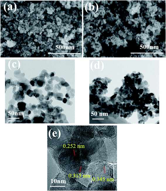 | ||
| Fig. 2 SEM and TEM images of pure TiO2 (a and c) and TiO2/15 wt% Fe3O4 (b and d) and (e) HRTEM images of TiO2/15 wt% Fe3O4. | ||
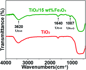
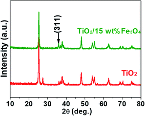
Fig. 3 and 4 depict the FTIR spectra and XRD patterns of pure TiO2 and TiO2/15 wt% Fe3O4, respectively. The obviously observed absorption band at 1640 and 3420 cm−1 in both of the catalysts corresponded to the bending vibration and symmetric stretching vibration of OH and surface absorbed water.19,24,25 Compared with FTIR spectra of pure TiO2, the peaks displayed in the FTIR spectra of TiO2/15 wt% Fe3O4 composites arose from not only OH group but also Fe–O vibration at 1087 cm−1.26 As displayed in Fig. 4, the peaks located at 2θ values of about 25.4°, 27.5°, 36.2°, 37.8°, 48.2° and 54.4° are the (101), (110), (101), (004), (200) and (204) diffraction peaks of TiO2. The intense and sharp peaks implied that the structure of TiO2 was well crystallized. The addition of Fe3O4 lowered the peak intensity of TiO2. In some other studies in the literature, the Fe3O4 characteristic peak of crystalline phase containing Fe3O4 could not be observed due to the low Fe3O4 content.21,27 In this paper, Similar result was found, the XRD characteristic diffraction peaks of Fe3O4 in TiO2/15 wt% Fe3O4 composites being not obvious because of the low loading content and high dispersion of Fe3O4. However, (311) crystal planes of Fe3O4 at 2θ = 35.86°,22 was slightly higher than that of pure TiO2, indicating the combination of TiO2 and Fe3O4.
XPS measurements were carried out to analyse the compositional and chemical states of samples and the results are shown in Fig. 5. Fig. 5a presents XPS spectrum of pure TiO2 and TiO2/15 wt% Fe3O4 composites. The full-scale XPS spectra indicated that there were elements O, Ti and C in TiO2, while TiO2/15 wt% Fe3O4 composites showed additional peaks of Fe 2p. The peak positions of Fe 2p3/2 and Fe 2p1/2 were 709.7 eV and 723.5 eV, respectively, which coincided with the previous literature.28 Actually, Fe3O4 should be described as FeO·Fe2O3, so the peaks are the comprehensive performance of Fe2+ and Fe3+. As for O 1s (Fig. 5c), the peak of pure TiO2 shifted from 529.2 eV to 528.7 eV for TiO2/15 wt% Fe3O4, implying the interaction between TiO2 and Fe3O4.
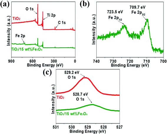 | ||
| Fig. 5 The XPS spectrum of pure TiO2 and TiO2/15 wt% Fe3O4 composites (a) Fe 2p from TiO2/15 wt% Fe3O4 composites (b) and O 1s from pure TiO2 and TiO2/15 wt% Fe3O4 composites (c). | ||
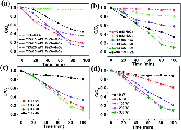
The removal efficiency of AMX under different conditions was investigated and the results were depicted in Fig. 6. As can be seen from the results, only 3.9% of the organic matter was removed even after 100 min in the absence the activation of Fe3O4, while the removal efficiency of AMX can increase to 85.0% with 15 wt% Fe3O4 dosage (Fig. 6a). Then it slightly decreases to 80.0 and 60.5% as the Fe3O4 content increases to 20% and 25%, respectively. According to Table 1, the BET surface areas of catalysts decrease from 59.5 to 24.8 m2 g−1 as the loading amount of Fe3O4 increases from 0 to 25%, which is almost independent of the removal efficiency of AMX. TiO2/15 wt% Fe3O4 showed the highest photo-Fenton catalytic performance. It was attributed to the fact that more Fe2+ sites were provided for H2O2 and thus more active ·OH was generated with the increase of the Fe3O4 content. However, overloading of Fe3O4 (TiO2/20 wt% Fe3O4 and TiO2/25 wt% Fe3O4) could block the light absorbance for TiO2 photocatalyst. In addition, excessive Fe2+ from Fe3O4 can consume ·OH on occasion of further increase in Fe3O4 content.29 Apparently, almost no obvious decrease of AMX was observed if there was no H2O2, which is essential in the oxidation of organics in photo-Fenton process (Fig. 6b). Within the first 30 minutes, more H2O2 corresponded to higher degradation rates. After 30 minutes, it showed the same trend when the concentration of H2O2 was below 24 mM. Undoubtedly, the increase of H2O2 resulted in the increase of ·OH, and thus the improvement in Fenton oxidation process. However, further increasing in H2O2 dosage from 24 to 30 mM, resulted in slight decrease in AMX removal indeed. This observation could be ascribed to the mechanism that excessive H2O2 could act as a self-scavenger for OH, following eqn (1) and (2), which leads to the greatly decrease of ·OH generation.30
| H2O2 + ·OH → ·OOH + H2O | (1) |
| ·OOH + ·OH → H2O + O2 | (2) |
| Samples | TiO2 | TiO2/10 wt% Fe3O4 | TiO2/15 wt% Fe3O4 | TiO2/20 wt% Fe3O4 | TiO2/25 wt% Fe3O4 |
|---|---|---|---|---|---|
| BET (m2 g−1) | 59.5 | 48.9 | 36.8 | 30.5 | 24.8 |
The initial pH of solution plays a vital role in chemical reaction by affecting the charge and other physicochemical property of substance in the mixture. The effect of pH on the photo-Fenton degradation of AMX was evaluated at pH values in the range of 1.01–7.45 (Fig. 6c). It is generally recognized that homogeneous Fenton process happens in acidic conditions and it came to the same conclusion in this photo-Fenton system.30,31 The AMX removal increased from 19.1% to 66.6% when the initial pH value decreased from 7.45 to 4.79. With further lower pH, more AMX was degraded and reached the highest at pH 2.84. This can be explained by the scramble of Fe3+ between OH− and H2O2. In other words, more Fe3+ will interact with OH− rather than H2O2 when pH is higher, leading to lower oxidation efficiency. Additionally, the LPML as the UV radiation source was used in the photoreactor. The light intensity in the SMSMPR was investigated to evaluate the kinetics of the photo-Fenton reaction via the electron hole formation, separation, and recombination rates (Fig. 6d). It was obvious that the concentration of AMX showed only slight decrease in the dark (light intensity = 0 W), indicating the limited adsorption capacity of TiO2/15 wt% Fe3O4 to AMX. At a low light intensity in the reactor (<200 W), the reaction rate increased remarkably with increasing light intensity, as the generation of electrons and holes was the predominant process. With further increase of light intensity (>200 W), the reaction rate increased slightly, owing to the high electron hole recombination. Meanwhile, electrons may have easily transferred from the catalyst to oxygen under the higher irradiation intensity, resulting in the generation of ·O2−, which is the rate limiting step for larger TiO2 particles. Therefore, light intensity of 200 W is the suitable operating condition for the SMSMPR.
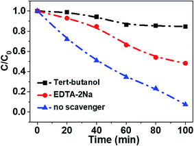
In order to reveal the charge transfer process between TiO2 and Fe3O4, AMX degradation mechanisms by TiO2/15 wt% Fe3O4 composite were further explored. First, the trapping experiments were conducted in the minified system. Specifically, 0.02 g photocatalysts were added into 50 mL AMX solution with a concentration 30 mg L−1 in the 100 mL photocatalysis reactor. EDTA-2Na (10 mM) and tert-butanol (TBA, 10 mM) were used as a hole scavenger and a hydroxyl radical scavenger (·OH), respectively (Fig. 7). The addition of a scavenger of holes (EDTA-2Na) caused a change in the photodegradation of AMX (50.9%). The degradation of AMX was significantly inhibited in the presence of TBA (15.2%). Thus, it is believed that ·OH and h+ should be the main active species in the photo-Fenton degradation of AMX process.
The mechanism of high AMX degradation in this photo-Fenton system was revealed in Fig. 8. In the TiO2/15 wt% Fe3O4 composite, excited electrons in the TiO2 rapidly transfer to the Fe3O4. The quick separation of photogenerated electron–hole pairs can effectively reduce the h+/e− pairs recombination, which contributes to AMX degradation by the h+ leaving in the valence band (route 1, Fig. 8). Meanwhile, introduction of Fe3O4 provided an additional ·OH generation pathway for AMX degradation (route 2, Fig. 8). The redox potential of Fe(II)/Fe(III) in Fe3O4 cycle is effective to activate H2O2 for the generation of ·OH. More importantly, the photogenerated electron trapped by Fe3O4 could facilitate the reduction process of Fe(III) to Fe(II) and then enhance the Fe(III)/Fe(II) cycle during the Fenton process. Therefore, the easier Fe(III)/Fe(II) cycle in TiO2/15 wt% Fe3O4 composite contributed to the higher activity and stability for AMX degradation.
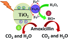 | ||
| Fig. 8 The proposed mechanism of photo-Fenton oxidation of AMX upon TiO2/15 wt% Fe3O4 composite photocatalyst under UV light irradiation. | ||
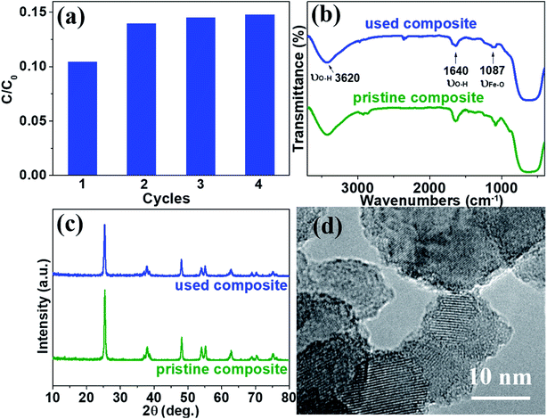
To examine the stability and repeatability of catalyst and SMSMPR, cycle experiments were carried out. After each cycle, an external magnetic field was imposed to the reactor and the photocatalyst was reclaimed, washed and used in next cycle. Fig. 9a presented the AMX degradation rates of four cycles, with the reaction time 100 min for each cycle. Except the first run (maybe because some loosely-combined catalyst leached), there was not significantly declined degradation ability of catalytic composites with more runs and the removal efficiency of AMX was as high as 85.3% even after 4 cycles. We also used FTIR, XRD and HRTEM to evaluate the difference between pristine and used TiO2/15 wt% Fe3O4. There was no obvious difference and the characteristic peaks of OH and Fe–O can be seen in both of the FTIR spectra (Fig. 9b). Fig. 9c illustrated that TiO2/15 wt% Fe3O4 sample after 4 reaction cycles maintained morphology, lattice parameters and crystallinity similar to those of fresh samples. There is no obvious morphology change from HRTEM images (Fig. 9d). These results reveal the high material stability of TiO2/15 wt% Fe3O4 and can be used as an environmentally friendly catalyst for photo-Fenton reaction.
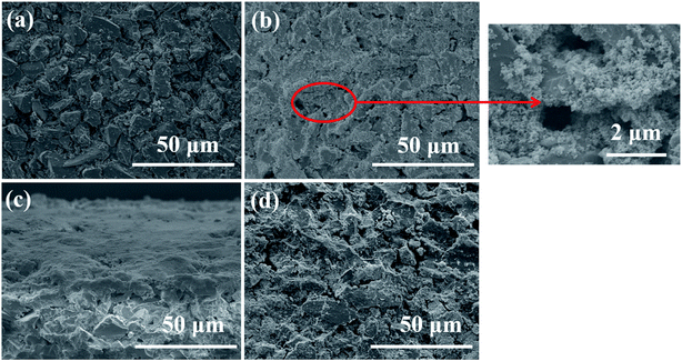
Subsequently, SEM was utilized to investigate the surface change of membrane in the SMSMPR and the results were delineated in Fig. 10. As can be seen, the raw ceramic membrane had rough surface and many micron-scale pores on the surface. After one cycle experiment, the TiO2–Fe3O4 particles were thickly deposited on the surface and even inside the pores of the membrane. However, most of the nanoparticles went away and the membrane recovered clean after backwashing treatment and exposure to the external magnetic field.
It is reported that the deposition of solid and pollutant can increase the trans-membrane pressure, lower the water flux and raise the cost of membrane technology.32 We also examined the trans-membrane pressure change during the cycle experiments and the result is given in Table 2. The initial trans-membrane pressure was measured after the cycle experiment started for 5 min and the final trans-membrane pressure was measured after the cycle experiment started for 100 min. As can be observed, the trans-membrane pressure was lifted much higher after one single cycle run. For example, the initial trans-membrane pressure was only 0.47 kPa, but the final was as high as 0.99 kPa after the second cycle started for 100 min. Although backwashing treatment can recover the trans-membrane pressure to some extent, the recovery effect was quite limited. By comparison, the use of external magnetic field maintained the trans-membrane pressure within a relatively low level even after 4 cycles.
| Pressure (kPa) | Cycle 1 | Cycle 2 | Cycle 3 | Cycle 4 |
|---|---|---|---|---|
| Initial trans-membrane pressure with backwashing only | 0.32 | 0.47 | 0.55 | 0.61 |
| Final trans-membrane pressure with backwashing only | 0.68 | 0.99 | 1.12 | 1.28 |
| Initial trans-membrane pressure with backwashing and external magnetic field | 0.32 | 0.39 | 0.41 | 0.40 |
| Final trans-membrane pressure with backwashing and external magnetic field | 0.50 | 0.51 | 0.60 | 0.55 |
Recently, researchers have used different kinds of magnetic photocatalysts to degrade organic pollutants. Chang et al. prepared Fe3O4/TiO2 magnetic photocatalyst for degradation of phenol.33 However, they utilized photocatalysis only instead of photo-Fenton process and then the degradation efficiency of organics reached maximum with the catalyst amount as much as 3 g L−1. As described above, photo-Fenton system has relatively higher degradation rate of pollutants under acidic conditions in most of the literature and we got the same result in the paper. Actually, researchers have been trying to overcome this drawback by adding chelating agents, such as ethylenediamine-N,N′-disuccinic acid (EDDS), ethylenediaminetetraacetic acid (EDTA) and nitrilotriacetic acid (NTA) in recent years,34 which could be adopted by the system in the paper. Another study also carried out recycling experiments to measure the repetitive use of the catalyst. With even better performance in reusability, the as-prepared Fe3O4@TiO2/SiO2 photocatalyst showed just a slight drop (from 94.5% to 90.1%) in removal efficiency after six cycles.19 This means that the repeatability of the SMSMPR system may be improved if stronger interaction between Fe3O4 and TiO2 was formed and further study is needed.
4. Conclusions
In summary, a novel photocatalysis reactor was successfully built and employed in the photo-Fenton process. Fe3O4 grown on a TiO2–Fe3O4 composite not only enhances the heterogeneous Fenton degradation of refractory organic compounds but also provides magnetism of the photocatalyst for magnetic separation from treated water. We combined an SMSMPR with the magnetic TiO2–Fe3O4 catalyst. The prepared TiO2–Fe3O4 composites showed high photo-Fenton catalytic activity for degradation of AMX. Cycle experiments demonstrate that the combination of backwashing treatment with magnetic separation could enhance the stability and reusability of the SMSMPR, promoting its practical application for removal of organic pollutants in aqueous solution.Conflicts of interest
There are no conflicts to declare.Acknowledgements
The authors are grateful for the financial support from the National Science and Technology Major Projects of Water Pollution Control and Management of China (2014ZX07206001), Major Science and Technology Program for Water Pollution Control and Treatment (2017ZX07202), and Singapore under its Campus for Research Excellence and Technological Enterprise (CREATE) programme (E2S2-CREATE project CS-B: Challenge of Emerging Contaminants on Environmental Sustainability in Megacities).References
- T. A. Ternes, M. Meisenheimer, D. McDowell, F. Sacher, H. J. Brauch, B. H. Gulde, G. Preuss, U. Wilme and N. Z. Seibert, Environ. Sci. Technol., 2002, 36, 3855–3863 CrossRef CAS PubMed.
- X. Guo, Z. Yan, Y. Zhang, X. Kong, D. Kong, Z. Shan and N. Wang, Environ. Sci. Pollut. Res., 2017, 24, 8769–8777 CrossRef CAS PubMed.
- D. A. Solís-Casados, L. Escobar-Alarcón, L. M. Gómez-Oliván, E. Haro-Poniatowski and T. Klimova, Fuel, 2017, 198, 3–10 CrossRef.
- Z. Feng, K. Odelius, G. K. Rajarao and M. Hakkarainen, Chem. Eng. J., 2018, 346, 557–566 CrossRef CAS.
- A. C. Fröhlich, G. S. dos Reis, F. A. Pavan, É. C. Lima, E. L. Foletto and G. L. Dotto, Environ. Sci. Pollut. Res., 2018, 25, 24713–24725 CrossRef PubMed.
- M. Awwad, F. Al-Rimawi, K. J. K. Dajani, M. Khamis, S. Nir and R. Karaman, Environ. Technol., 2015, 36, 2069–2078 CrossRef CAS PubMed.
- J. Svojitka, L. Dvořák, M. Studer, J. O. Straub, H. Frömelt and T. Wintgens, Bioresour. Technol., 2017, 229, 180–189 CrossRef CAS PubMed.
- X. Wei, X. Bao, J. Wu, C. Li, Y. Shi, J. Chen, B. Lv and B. Zhu, RSC Adv., 2018, 8, 10396–10408 RSC.
- C. Sheng, A. G. A. Nnanna, Y. Liu and J. D. Vargo, Sci. Total Environ., 2016, 550, 1075–1083 CrossRef CAS PubMed.
- G. Divyapriya, R. Srinivasan, I. Nambi and J. Senthilnathan, Electrochim. Acta, 2018, 283, 858–870 CrossRef CAS.
- S. Nachiappan and K. Muthukumar, Clean: Soil, Air, Water, 2014, 42, 1526–1533 CAS.
- Y. Segura, F. Martínez and J. A. Melero, Appl. Catal., B, 2013, 136–137, 64–69 CrossRef CAS.
- K. Nakata and A. Fujishima, J. Photochem. Photobiol., C, 2012, 13, 169–189 CrossRef CAS.
- A. Fujishima and K. Honda, Nature, 1972, 238, 37–38 CrossRef CAS PubMed.
- A. Ajmal, I. Majeed, R. N. Malik, H. Idriss and M. A. Nadeem, RSC Adv., 2014, 4, 37003–37026 RSC.
- A. W. Vermilyea and B. M. Voelker, Environ. Sci. Technol., 2009, 43, 6927–6933 CrossRef CAS PubMed.
- A. L. Giraldo-Aguirre, E. A. Serna-Galvis, E. D. Erazo-Erazo, J. Silva-Agredo, H. Giraldo-Ospina, O. A. Flórez-Acosta and R. A. Torres-Palma, Environ. Sci. Pollut. Res., 2018, 25, 20293–20303 CrossRef CAS PubMed.
- N. M. Costa, G. D. Silva, E. O. Marson, E. M. Richter, A. E. H. Machado and A. G. Trovó, Fuel, 2018, 221, 110–115 CrossRef CAS.
- Z.-D. Li, H.-L. Wang, X.-N. Wei, X.-Y. Liu, Y.-F. Yang and W.-F. Jiang, J. Alloys Compd., 2016, 659, 240–247 CrossRef CAS.
- F. Pellegrino, L. Pellutiè, F. Sordello, C. Minero, E. Ortel, V.-D. Hodoroaba and V. Maurino, Appl. Catal., B, 2017, 216, 80–87 CrossRef CAS.
- Y. Fan, C. Ma, W. Li and Y. Yin, Mater. Sci. Semicond. Process., 2012, 15, 582–585 CrossRef CAS.
- Y. P. Yew, K. Shameli, M. Miyake, N. Kuwano, N. Khairudin, S. E. B. Mohamad and K. X. Lee, Nanoscale Res. Lett., 2016, 11, 276 CrossRef PubMed.
- N. Zhao, S. Wu, C. He, Z. Wang, C. Shi, E. Liu and J. Li, Carbon, 2013, 57, 130–138 CrossRef CAS.
- S. S. Latif, S. Nahar and M. Hasan, J. Reinf. Plast. Compos., 2015, 34, 187–195 CrossRef CAS.
- S. N. Timmiati, A. A. Jalil, S. Triwahyono, H. D. Setiabudi and N. H. R. Annuar, Appl. Catal., A, 2013, 459, 8–16 CrossRef CAS.
- P. K. Boruah, B. Sharma, I. Karbhal, M. V. Shelke and M. R. Das, J. Hazard. Mater., 2017, 325, 90–100 CrossRef CAS PubMed.
- R. Nagarjuna, S. Challagulla, R. Ganesan and S. Roy, Chem. Eng. J., 2017, 308, 59–66 CrossRef CAS.
- A. P. Grosvenor, B. A. Kobe, M. C. Biesinger and N. S. McIntyre, Surf. Interface Anal., 2004, 36, 1564–1574 CrossRef CAS.
- Y. Zhang, K. Zhang, C. Dai, X. Zhou and H. Si, Chem. Eng. J., 2014, 244, 438–445 CrossRef CAS.
- S. Chen, Y. Wu, J. Wu, G. Li, G. Meng, X. Guo and Z. Liu, Appl. Clay Sci., 2017, 136, 103–111 CrossRef CAS.
- C. Xiao, J. Li and G. Zhang, J. Cleaner Prod., 2018, 180, 550–559 CrossRef CAS.
- H. Chang, H. Liang, F. Qu, B. Liu, H. Yu, X. Du, G. Li and S. A. Snyder, J. Membr. Sci., 2017, 540, 362–380 CrossRef CAS.
- J. Chang, Q. Zhang, Y. Liu, Y. Shi and Z. Qin, J. Mater. Sci.: Mater. Electron., 2018, 29, 8258–8266 CrossRef CAS.
- L. Clarizia, D. Russo, I. Di Somma, R. Marotta and R. Andreozzi, Appl. Catal., B, 2017, 209, 358–371 CrossRef CAS.
| This journal is © The Royal Society of Chemistry 2019 |

