 Open Access Article
A novel positively charged composite nanofiltration membrane based on polyethyleneimine with a tunable active layer structure developed via interfacial polymerization
Zhibin Jiangabe,
Jing Miao *ac,
Yuantao Heab,
Kai Tua,
Shunquan Chena,
Rui Zhang*c,
Ling Zhang
 *d and
Hao Yang
 *b
*b
aGuangdong Key Laboratory of Membrane Materials and Membrane Separation, Guangzhou Institute of Advanced Technology, Chinese Academy of Sciences (CAS), Guangzhou 511458, PR China. E-mail: jing.miao@giat.ac.cn; jmiao@jinzhenghb.com; Fax: +86-2022912525; Tel: +86-13829708450
bKey Laboratory for Green Chemical Process of Ministry of Education, School of Environmental Ecology and Biological Engineering, Wuhan Institute of Technology, Wuhan, 430205, PR China. E-mail: hyang@wit.edu.cn
cShandong Disk Tube Reverse Osmosis (DTRO) Membrane Engineering Laboratory, The New Water Technology, Inc. (NEWA), China. E-mail: niureal@gmail.com
dSchool of Resource and Environment, University of Jinan, Jinan 250022, PR China. E-mail: chm_zhangl@ujn.edu.cn
eSchool of Chemistry and Environment, South China Normal University, Guangzhou 510631, China
First published on 8th April 2019
Abstract
A novel positively charged composite nanofiltration (NF) membrane with tunable active layer structure was successfully developed via interfacial polymerization on a polysulfone (PSF) ultrafiltration (UF) membrane surface, using polyethyleneimine (PEI) as the monomer of the aqueous phase, and a mixture of isophthaloyl dichloride (IPC) and tri-mesoyl chloride (TMC) as the monomer of the organic phase. Interestingly, a synergetic effect of the mass ratio of IPC and TMC was observed on the pore size and the structure of the active layer of the resultant polyamide (PA)/polysulfone (PSF) composite NF membrane. The rejection (R) to the inorganic electrolytes increased with the mass ratio of IPC to TMC, while the permeate flux (F) escalated up to a 1![[thin space (1/6-em)]](https://www.rsc.org/images/entities/char_2009.gif) :
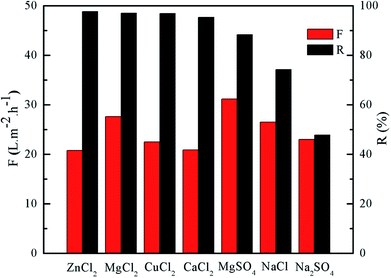
:![[thin space (1/6-em)]](https://www.rsc.org/images/entities/char_2009.gif) 1 mixing ratio of IPC to TMC and dropped at higher mixing ratios. The rejection to different inorganic electrolytes decreased in the order of ZnCl2, MgCl2, CaCl2, CuCl2, MgSO4, NaCl, and Na2SO4. At ambient temperature and 0.4 MPa, the optimized membrane demonstrated R and F to 1 g L−1 MgCl2 aqueous solution as 98.1% and 27.6 L m−2 h−1, respectively. Its rejection to various dyes reduced significantly in the order of cationic red X-GTL (100%), rhodamine B (94.2%), cationic gold yellow X-GL (93.5%), and brilliant blue KN-R (43.9%), in agreement with the decrease in the molecular weight (Mw) and the overall charges of the dye.
1 mixing ratio of IPC to TMC and dropped at higher mixing ratios. The rejection to different inorganic electrolytes decreased in the order of ZnCl2, MgCl2, CaCl2, CuCl2, MgSO4, NaCl, and Na2SO4. At ambient temperature and 0.4 MPa, the optimized membrane demonstrated R and F to 1 g L−1 MgCl2 aqueous solution as 98.1% and 27.6 L m−2 h−1, respectively. Its rejection to various dyes reduced significantly in the order of cationic red X-GTL (100%), rhodamine B (94.2%), cationic gold yellow X-GL (93.5%), and brilliant blue KN-R (43.9%), in agreement with the decrease in the molecular weight (Mw) and the overall charges of the dye.
1. Introduction
Membrane separation technology is the most economic approach among the seawater desalination technologies. Nanofiltration (NF) is a pretreatment technology for the reverse osmosis (RO) seawater desalination process, which effectively removes most di-/multi-valent ions (Mg2+, Ca2+, and SO42−, etc.) from seawater as well as some monovalent ions (Na+, K+, and Cl−, etc.), and hence reduces the operating pressure of the RO process.1–4 In addition to its use in pretreatment for seawater desalination, NF is also widely utilized in applications such as wastewater treatment, water purification, water softening, concentration and separation of active intermediates, etc.5–9Most of the currently available commercial NF membranes are negatively charged composite NF membranes for desalination,10 ionic exchange,11 dye purification,12 toluidine blue O separation,13 osmotic power generation from municipal wastewater,14 removal of typical pharmaceutical molecules,15 etc. As the NF technology has found vast applications in various industries, the demand for novel positively charged composite NF membranes has grown tremendously.
Interfacial polymerization (IP) on an ultrafiltration (UF) membrane at ambient temperature has been employed extensively in the fabrication of positively charged composite NF membranes due to its ease of operation, flexibility, effectiveness, and economical efficiency.16,17 The IP process occurs at the interface between the aqueous phase and the organic phase, as the water-soluble monomer comes into contact with the organic monomer.18,19 Most of the commercial NF membranes are PA composite NF membranes, fabricated using amine and acyl chloride as the aqueous monomer and the organic monomer, respectively. The rejection performances of the NF membrane were tuned by the types of monomer, the preparation method, the post heat treatment, the molecular weight cut-off (MWCO) of the base membrane, etc.20–23 In order to improve the rejection performance, anti-oxidization and antifouling properties, numerous studies have been focused on employing novel monomers, adding surfactants and additives to the aqueous or organic phase, and the conditions of post heat treatment, etc.18,24–26
Due to rich active amine groups in the polymer chains, polyethyleneimine (PEI) has been widely employed to prepare the positively charged composite NF membranes. The resultant PEI composite NF membranes showed high ion selectivity and rejection to positively charged solutes.
Several literatures reported fabrication, characterizations, and rejection performance of the positively charged composite NF membranes prepared via IP, using PEI as the monomer in the aqueous phase. Chiang,27 Sun,28 and Thong,29 et al. have investigated the impact of the chemical structure of the di-/multi-amine on the performance of the resultant composite NF membrane. It was found that the increase in the charged group in the resultant composite NF membranes could enhance the rejection to inorganic electrolytes and does not affect the permeate flux. The rejection also increased with the molecular weight (Mw) of PEI due to the decrease in the membrane pore size, while the permeate flux decreased. The above observation is contrary to the results by Thong et al. Furthermore, Gao,30 and Lee, et al.31 investigated the influence of the acyl chloride on the rejection performance of the resultant composite NF membrane. In the work done by Lee, et al., a novel pH-stable composite NF membrane was prepared with interfacial polymerization, using PEI and cyanuric chloride (CC) as the monomers in the aqueous and organic phases, respectively. The resultant composite NF membrane could be stable at extreme pHs, because the functional groups were able to resist the attacks by the nucleophilic and electrophilic reagents. In another word, rejection performance, including the rejection (R), the permeate flux (F), and the MWCO, was maintained with the resultant composite NF membranes immersed in HNO3 and NaOH aqueous solutions at pH 1 and pH 13, respectively, for more than one month. Moreover, a novel antifouling PEI-based thin film composite (TFC) NF membrane was developed via an in situ manipulation approach, using dextran (Dex) conjugate of PEI (PEI-Dex) as a new monomer or co-monomer together with TMC in the interfacial polymerization (IP).32 The resultant PEI-based membrane exhibited excellent antifouling properties compared to that of conventional TFC NF membranes based on piperazine and it was suitable for long-term water softening without frequent membrane cleaning.
The low-pressure PEI composite NF membranes with relatively high rejection (R) and permeate fluxes (F) had been developed by adjusting the parameters in preparation process, such as monomer concentration, IP time, the condition of post heat treatment, etc. Molecular assembly is another effective way to optimize the rejection performance of the PEI based composite NF membrane. TFC NF membranes with a layer-by-layer structure formed via IP between PEI and TMC were developed by repeating cycles of sequential reactant depositions and reactions for better salt rejection. The results suggested that the PEI-TMC NF membranes were much more permeable than the TMC-PEI NF membranes, and the proper post heat treatment boosted the salt rejection of the resultant TFC NF membrane.33
The research mentioned above has shown vast improvement in the properties of the positively charged PEI composite NF membranes, including rejection, permeate flux, anti-fouling characteristic, and pH stability, etc. However, the relatively low permeate flux, which directly affects the production efficiency of the membrane, still hinders the wide application of the PEI composite NF membranes in industries. To obtained polyamide-based composite NF hollow fiber membranes with desirable characteristics for water softening at relatively low operating pressure in the ultrafiltration range, Fang, et al.,34 employed the aqueous phase containing a mixture of PEI and piperazine (PIP) to react with TMC in the organic phase. Synergetic effect of PEI and PIP was found on the formation of the selective layer. Specifically, the resultant membrane demonstrated higher water permeability and salt rejection at a certain PIP to PEI ratio. Therefore, it could be concluded that the ratio of reacting monomers played a critical role on the permeability and the active layer thickness of the resultant polyamide-based membrane.
In this work, a novel positively charged composite NF membrane has been fabricated for the first time via IP between PEI and a mixture of IPC and TMC of various mass ratio. It was the first time that a novel kind of positively charged composite NF membrane has been fabricated with the IP between PEI and the mixture of IPC and TMC with different mass ratio. The resultant membranes were characterized by SEM, AFM, ATR-FTIR. Contact angle and zeta potential were employed to determine their hydrophilicity and electrokinetic characteristics, respectively. The investigations were conducted to understand the effect of the mass ratio of IPC to TMC on the rejection performance of the PA/PSF composite NF membrane, rejection of an optimized membrane to different inorganic electrolytes, and how MW and charges affects rejections to dyes of different structures.
It was found that the PA/PSF composite NF membrane with the high rejection rate was more permeable compared with the membranes developed with TMC or IPC alone as the organic phase IP monomer. The composite NF membranes with relatively thinner active layers could be easily obtained via controlling the ratios of IP monomers. This work will provide the base for the development and application of the TFC NF membranes prepared with IP, using PEI as the monomer of the aqueous phase.
2. Experimental section
2.1. Chemicals and materials
The polysulfone (PSF) ultrafiltration (UF) substrate, with a MWCO of 30 kDa, were provided by Pureach Tech Ltd (Beijing, China). Polyethyleneimine (PEI, MW: 70![[thin space (1/6-em)]](https://www.rsc.org/images/entities/char_2009.gif) 000 Da, 50 wt%), trimesoyl chloride (TMC, 98.0%), and isophthaloyl chloride (IPC, 98.0%) were purchased from Shanghai Macklin Biochemical Co., Ltd., China. n-Hexane and all inorganic electrolytes with AR grade, including ZnCl2, MgCl2, CaCl2, CuCl2, MgSO4, NaCl, and Na2SO4, were purchased from SINOPHARM, China. The dyes, including cationic red X-GTL, rhodamine B, cationic gold yellow X-GL, and reactive brilliant blue KN-R, were obtained from Tianjin Longshengxiang Science and Technology Ltd., China. Fig. 1 shows the molecular structures of different dyes. Milli-Q water was used for the preparation and the permeation tests. All chemicals were used without further purification.
000 Da, 50 wt%), trimesoyl chloride (TMC, 98.0%), and isophthaloyl chloride (IPC, 98.0%) were purchased from Shanghai Macklin Biochemical Co., Ltd., China. n-Hexane and all inorganic electrolytes with AR grade, including ZnCl2, MgCl2, CaCl2, CuCl2, MgSO4, NaCl, and Na2SO4, were purchased from SINOPHARM, China. The dyes, including cationic red X-GTL, rhodamine B, cationic gold yellow X-GL, and reactive brilliant blue KN-R, were obtained from Tianjin Longshengxiang Science and Technology Ltd., China. Fig. 1 shows the molecular structures of different dyes. Milli-Q water was used for the preparation and the permeation tests. All chemicals were used without further purification.
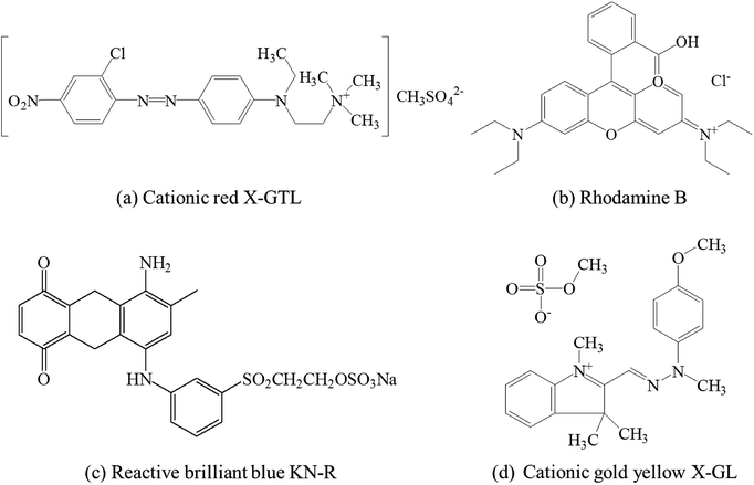 | ||
| Fig. 1 Chemical structures of different dyes.35 | ||
2.2. Preparation of the positively charged PA/PSF composite NF membranes
The positively charged polyamide/polysulfone (PA/PSF) composite NF membranes were fabricated via interfacial polymerization (IP).36 The preparation process was described as the following. The PSF UF substrates were immersed in 3.7 wt% PEI aqueous solution for 5 min, and then the excess aqueous solution was removed. The membranes were dried at 30 °C for 30 min. After drying, the membranes were immersed for 90 s in 0.25 w/v% acyl chloride n-hexane solution containing the IPC and TMC mixed at different mass ratio. After IP, the PA/PSF composite NF membranes were rinsed extensively and stored for further uses. Especially, the membrane samples fabricated as the mass ratios of IPC to TMC were 0![[thin space (1/6-em)]](https://www.rsc.org/images/entities/char_2009.gif) :
:![[thin space (1/6-em)]](https://www.rsc.org/images/entities/char_2009.gif) 1, 1
1, 1![[thin space (1/6-em)]](https://www.rsc.org/images/entities/char_2009.gif) :
:![[thin space (1/6-em)]](https://www.rsc.org/images/entities/char_2009.gif) 1, and 1
1, and 1![[thin space (1/6-em)]](https://www.rsc.org/images/entities/char_2009.gif) :
:![[thin space (1/6-em)]](https://www.rsc.org/images/entities/char_2009.gif) 0, respectively, were labeled as PA01/PSF, PA11/PSF, and PA10/PSF, respectively. Fig. 2 shows the structures of PSF, PEI, IPC, TMC molecules, and possible polymer network of PA active layer for PA/PSF composite NF membranes.
0, respectively, were labeled as PA01/PSF, PA11/PSF, and PA10/PSF, respectively. Fig. 2 shows the structures of PSF, PEI, IPC, TMC molecules, and possible polymer network of PA active layer for PA/PSF composite NF membranes.
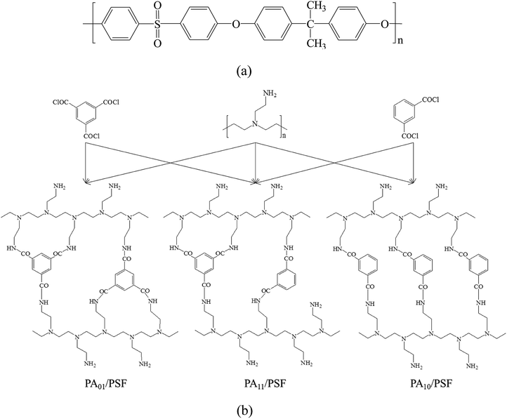 | ||
| Fig. 2 Chemical structures of (a) PSF UF substrate and (b) possible network of PA active layer for the positively charged PA/PSF composite NF membranes. | ||
2.3. Characterizations of the resultant TFC NF membranes
The surface and the cross-section morphologies of PSF UF substrate and the positively charged PA01/PSF, PA11/PSF, and PA10/PSF composite NF membranes, were observed with scanning electron microscope (SEM, Phenom XL, Netherlands). Before observation, these samples were fractured in liquid nitrogen, and were sprayed with gold on the surface by using an ion sputter JS-16009. The 3-D morphology and the roughness of the membrane surface were obtained on an atomic force microscope (AFM, SPM-9700, Shimadzu Corp., Japan). The chemical structures of the membranes were investigated by attenuated total reflectance-fourier transform infrared (ATR-FTIR) spectroscope (Nicolet iS10, Thermo Fisher Scientific, the United States). Furthermore, the hydrophilicities of the membranes were characterized with a water contact angle (CA) goniometer (Drop Shape Analyzer-DSA30, KRÜSS, Germany). The electro-kinetic characteristic of the membrane surface was characterized with an electrokinetic analyzer (SurPASS™ 3, Anton Paar GmbH, Austria) at pH ranging from 2 to 10, using 0.001 mol L−1 KCl aqueous solution. The surface zeta potential was calculated according to the Helmholtz-Smoluchowski equation with the Fairbrother and Mastin substitution.372.4. Rejection performances
The rejection performances of the resultant composite NF membranes were evaluated with a cross-flow filtration equipment with an effective membrane area of 70 cm2. The concentrations of the inorganic electrolytes, the dyes, and the PEG with different MW herein are 1.0 g L−1. R and F were calculated with the following equations.
 | (1) |
 | (2) |
3. Results and discussions
3.1. Characterization of membrane material
![[thin space (1/6-em)]](https://www.rsc.org/images/entities/char_2009.gif) :
:![[thin space (1/6-em)]](https://www.rsc.org/images/entities/char_2009.gif) 1 (labelled as PA01/PSF), the surface of PA01/PSF membrane was covered with small granules, like PSF UF substrate. As this mass ratio being increased to 1
1 (labelled as PA01/PSF), the surface of PA01/PSF membrane was covered with small granules, like PSF UF substrate. As this mass ratio being increased to 1![[thin space (1/6-em)]](https://www.rsc.org/images/entities/char_2009.gif) :
:![[thin space (1/6-em)]](https://www.rsc.org/images/entities/char_2009.gif) 1, the small granules disappeared, the wrinkles showed up in the same pattern of the tiled graphene oxide surface. In addition, the active layer at 1
1, the small granules disappeared, the wrinkles showed up in the same pattern of the tiled graphene oxide surface. In addition, the active layer at 1![[thin space (1/6-em)]](https://www.rsc.org/images/entities/char_2009.gif) :
:![[thin space (1/6-em)]](https://www.rsc.org/images/entities/char_2009.gif) 1 mixing ratio was measured to be thinner than the mixing ratio of 0
1 mixing ratio was measured to be thinner than the mixing ratio of 0![[thin space (1/6-em)]](https://www.rsc.org/images/entities/char_2009.gif) :
:![[thin space (1/6-em)]](https://www.rsc.org/images/entities/char_2009.gif) 1, and the surface was coarser, possibly resulting in a higher specific surface area.44 The rougher surface and thinner thickness were considered to be beneficial to the water permeability of the membrane because it enlarges the effective area of the membrane surface.45 However, the morphology of the membrane surface changed again at the mass ratio of 1
1, and the surface was coarser, possibly resulting in a higher specific surface area.44 The rougher surface and thinner thickness were considered to be beneficial to the water permeability of the membrane because it enlarges the effective area of the membrane surface.45 However, the morphology of the membrane surface changed again at the mass ratio of 1![[thin space (1/6-em)]](https://www.rsc.org/images/entities/char_2009.gif) :
:![[thin space (1/6-em)]](https://www.rsc.org/images/entities/char_2009.gif) 0. Twisted particles were detected in Fig. 3(g). The above results strongly suggested that the surface morphology of PA active layer was highly correlated with the structure and the mass ratio of acyl chloride.
0. Twisted particles were detected in Fig. 3(g). The above results strongly suggested that the surface morphology of PA active layer was highly correlated with the structure and the mass ratio of acyl chloride.
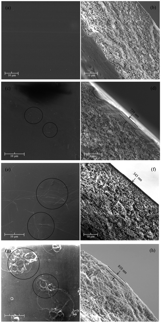 | ||
| Fig. 3 The surface and cross-section images of (a and b) PSF UF substrate, (c and d) PA01/PSF, (e and f) PA11/PSF and (g and h) PA10/PSF positively charged TFC NF membranes at 6000× magnification. | ||
As for the cross-section morphologies shown in Fig. 3(b), (d), (f) and (h), it could be observed that each cross section of PA/PSF composite NF membranes was composed of two distinct layers with one being a spongy supporting layer, and the other being a tighter and thinner PA active layer. Furthermore, the thickness of PA active layer for PA01/PSF, PA11/PSF, and PA10/PSF composite NF membranes were measured to be 739 nm, 343 nm, and 810 nm, respectively. The above results suggested that the resultant PA composite NF membranes fabricated at 1![[thin space (1/6-em)]](https://www.rsc.org/images/entities/char_2009.gif) :
:![[thin space (1/6-em)]](https://www.rsc.org/images/entities/char_2009.gif) 1 mass ratio of IPC to TMC have the thinnest PA active layer among the three membranes. Similar morphologies have been reported in the literatures.38,41,43,46,47
1 mass ratio of IPC to TMC have the thinnest PA active layer among the three membranes. Similar morphologies have been reported in the literatures.38,41,43,46,47
Based on the above results, it could be concluded that a thin functional active layer has been successfully prepared onto the PSF UF substrate via the interfacial polymerization between PEI and a mixture of IPC and TMC. As the total mass of acyl chloride was set at a certain value, the higher mass ratio of IPC to TMC was, the more –NH2 would be remained. This will result in the aggregations of excess PEI molecules on the membrane surface in the form of wrinkles and twisted particles, as observed in Fig. 3(c), (e) and (g).27
| Membrane samples | Rrms/nm |
|---|---|
| PSF | 4.23 ± 0.09 |
| PA01/PSF | 4.57 ± 0.06 |
| PA11/PSF | 43.90 ± 0.05 |
| PA10/PSF | 11.83 ± 0.07 |
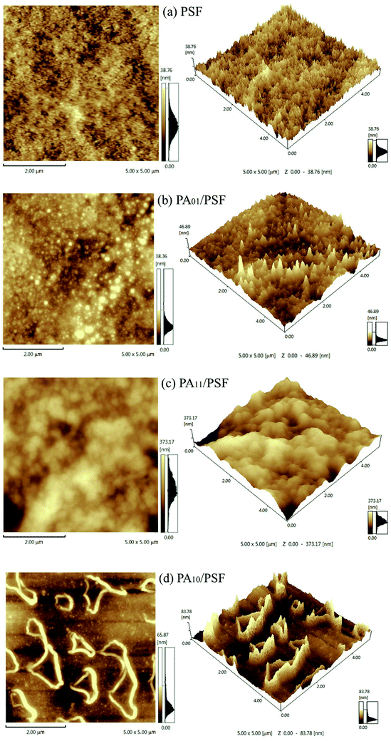 | ||
| Fig. 4 The 2-D and 3-D surface morphologies of (a) PSF UF substrate, (b) PA01/PSF, (c) PA11/PSF and (d) PA10/PSF positively charged composite NF membranes in an area of 5 μm × 5 μm. | ||
The Rrms of PSF UF substrate and PA/PSF composite NF membrane were summarized in Table 1.40 The commercial PSF UF substrate exhibited a relatively smooth surface with the lowest Rrms of 4.23 nm. After the PA active layer was introduced onto the PSF UF substrate, rough surfaces of wrinkles or twisted particles became visible, and the roughness increased with the mass ratio of IPC to TMC. The Ra of PA01/PSF, PA11/PSF, and PA10/PSF composite NF membranes were 4.57 nm, 43.90 nm, and 11.83 nm, respectively, as the mass ratio of IPC to TMC changed from 0![[thin space (1/6-em)]](https://www.rsc.org/images/entities/char_2009.gif) :
:![[thin space (1/6-em)]](https://www.rsc.org/images/entities/char_2009.gif) 1 to 1
1 to 1![[thin space (1/6-em)]](https://www.rsc.org/images/entities/char_2009.gif) :
:![[thin space (1/6-em)]](https://www.rsc.org/images/entities/char_2009.gif) 0. Particularly, the one with wrinkled PA active layer, similar to the tiled graphene oxide surface, would have the largest roughness, suggesting that the results measured by AFM agreed with the morphologies obtained from SEM.41 Besides, the membrane with the higher roughness corresponded to the higher specific surface area, which benefited the permeate flux. The results suggested that the surface morphology and the roughness of the PA/PSF composite NF membranes were mainly determined by the mass ratio of IPC to TMC. The higher mass ratio of IPC to TMC was, the more –NH2 was remained, and the larger particles on the selective layer surface would be.
0. Particularly, the one with wrinkled PA active layer, similar to the tiled graphene oxide surface, would have the largest roughness, suggesting that the results measured by AFM agreed with the morphologies obtained from SEM.41 Besides, the membrane with the higher roughness corresponded to the higher specific surface area, which benefited the permeate flux. The results suggested that the surface morphology and the roughness of the PA/PSF composite NF membranes were mainly determined by the mass ratio of IPC to TMC. The higher mass ratio of IPC to TMC was, the more –NH2 was remained, and the larger particles on the selective layer surface would be.
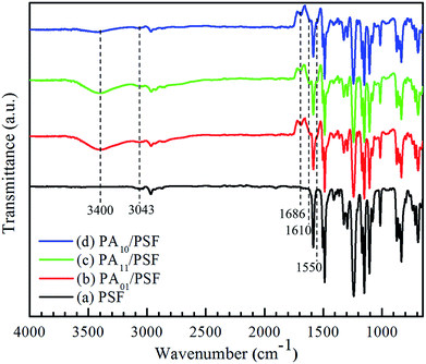
![[double bond, length as m-dash]](https://www.rsc.org/images/entities/char_e001.gif) O stretching.38,39,46–49 Another new peak with wide and strong absorbance presented at 3400 cm−1 might be attributed to the N–H stretching peak in PEI molecule.36,43,49,50 The two new absorbance peaks suggested that amine groups of PEI interacted with acyl chloride groups of IPC and TMC at interface and produced the amide bond. The intensity of absorbance peak at 3400 cm−1 became weaker with an increase in the mass ratio of IPC to TMC. On the other hand, two new weak absorbance peaks at 1610 cm−1 and 1550 cm−1 arose as well, and the intensity of absorbance peak at 3043 cm−1 increased. These results suggested that the PA/PS composite NF membrane should contain the aromatic rings as introduced by acyl chloride molecules. The new weak absorbance peaks at 1610 cm−1 and 1550 cm−1 could be attributed to the C
O stretching.38,39,46–49 Another new peak with wide and strong absorbance presented at 3400 cm−1 might be attributed to the N–H stretching peak in PEI molecule.36,43,49,50 The two new absorbance peaks suggested that amine groups of PEI interacted with acyl chloride groups of IPC and TMC at interface and produced the amide bond. The intensity of absorbance peak at 3400 cm−1 became weaker with an increase in the mass ratio of IPC to TMC. On the other hand, two new weak absorbance peaks at 1610 cm−1 and 1550 cm−1 arose as well, and the intensity of absorbance peak at 3043 cm−1 increased. These results suggested that the PA/PS composite NF membrane should contain the aromatic rings as introduced by acyl chloride molecules. The new weak absorbance peaks at 1610 cm−1 and 1550 cm−1 could be attributed to the C![[double bond, length as m-dash]](https://www.rsc.org/images/entities/char_e001.gif) C stretching peaks of TMC and IPC.46,47
C stretching peaks of TMC and IPC.46,47
| Membrane | Contact angle (°) |
|---|---|
| PSF | 75.1 ± 0.6 |
| PA01/PSF | 53.7 ± 0.7 |
| PA11/PSF | 44.7 ± 0.2 |
| PA10/PSF | 51.6 ± 0.4 |
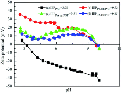 | ||
| Fig. 6 Zeta potentials of (a) PSF UF substrate, (b) PA01/PSF, (c) PA11/PSF and (d) PA10/PSF composite NF membranes. | ||
The surface charge fluctuated below pH 7, probably due to the unstable polyamide-based membrane at extreme pH. Especially, the polyamide membranes prepared with IPC as the organic monomer were less stable than those made with TMC, because its' C–N bond would be much more easily attacked by the H+ without the protection of the steric hindrance effect, and the lonely-pair electrons on the N atom would be captured by H+ to form N–H bond. Then a portion of amide groups would be destroyed to produce dissociative amido and carboxyl groups via hydrolysis, resulting the fluctuation of the surface charge below pH 7.47
3.2. Effect of mass ratio of IPC to TMC on the rejection performance of the PA/PSF composite NF membrane
Fig. 8 shows the effect of mass ratio of IPC to TMC on the rejection performance of the PA/PSF composite NF membrane. The rejection to MgCl2 increased from 94.5% to 97.8% with mass ratio of IPC to TMC, while the permeate flux of PA/PSF composite NF membrane grew gradually with mass ratio of IPC to TMC till it reached 1![[thin space (1/6-em)]](https://www.rsc.org/images/entities/char_2009.gif) :
:![[thin space (1/6-em)]](https://www.rsc.org/images/entities/char_2009.gif) 1 and lowered at higher mass ratio of IPC to TMC. The maximum permeate flux was 24.7 L m−2 h−1 at 1
1 and lowered at higher mass ratio of IPC to TMC. The maximum permeate flux was 24.7 L m−2 h−1 at 1![[thin space (1/6-em)]](https://www.rsc.org/images/entities/char_2009.gif) :
:![[thin space (1/6-em)]](https://www.rsc.org/images/entities/char_2009.gif) 1 mass ratio of IPC to TMC. The chemical structure of the active layer changed with mass ratio of IPC and TMC, resulting in the variation of rejection performance of PA/PSF composite NF membrane. Thus, a positively charged PA/PSF composite NF membrane with tunable active layer could be developed by adjusting the mass ratio of IPC and TMS in the organic phase.
1 mass ratio of IPC to TMC. The chemical structure of the active layer changed with mass ratio of IPC and TMC, resulting in the variation of rejection performance of PA/PSF composite NF membrane. Thus, a positively charged PA/PSF composite NF membrane with tunable active layer could be developed by adjusting the mass ratio of IPC and TMS in the organic phase.
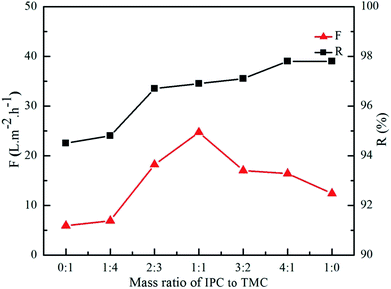 | ||
| Fig. 8 Effect of mass ratio of IPC to TMC on separation performance of positively charged PA/PSF composite NF membranes. | ||
3.3. Rejection performance of the positively charged PA11/PSF composite NF membrane
| Dye | Mw (Da) | Maximum absorption wavelength (nm) | R (%) | F (L m−2 h−1) |
|---|---|---|---|---|
| Brilliant blue KN-R | 626.5 | 592 | 43.9 | 18.6 |
| Cationic red X-GTL | 502.0 | 530 | 100.0 | 14.9 |
| Rhodamine B | 479.0 | 560 | 94.2 | 13.9 |
| Cationic gold yellow X-GL | 433.5 | 441 | 93.5 | 19.6 |
Among the three cationic dyes, the rejection to divalent cationic red X-GTL was the highest, while the rejections to the monovalent positively charged rhodamine B and cationic gold yellow X-GL were lower and the difference in the rejections of the two dyes were negligible. However, the negatively charged dye with the highest Mw, reactive brilliant blue KN-R exhibited the lowest rejection among the four dyes, suggesting that the charge of the dye (anionic vs. cationic) had huge impact on the rejection of the PA11/PSF. Both Donnan exclusion effect and steric-hindrance effect played key roles in the rejection to dyes with different Mw and charge.61,62
4. Conclusions
In this work, a novel positively charged composite NF membrane with tunable active layer structures was prepared by adjusting the mass ratio of IPC to TMC in the organic phase via interfacial polymerization. The characterizations with SEM, AFM, ATR-FTIR, contact angle, and zeta potential measurement confirmed the successful fabrication of the desirable membranes with hydrophilic nature and revealed the microscopic morphologies of wrinkles or twisted particles at membrane surface.Synergetic effect was found in a mixture of IPC and TMC as the active layer. The resultant PA/PSF membranes not only had relatively thinner active layers, but also were more permeable than the membranes developed with TMC or IPC alone. Additionally, the optimized resultant positively charged PA/PSF composite NF membrane showed excellent rejection performance to cationic dyes and inorganic electrolytes of divalent cations. In summary, the structure of the active layer could be tuned by regulating the mass ratio of two monomers in organic phase, which in turn was closely related to permeate flux.
The results will provide rich information to establish a foundation for the development of PEI TFC positively charged PA composite NF membranes bearing great R and F performance.
Conflicts of interest
There are no conflicts of interest to declare.Abbreviation
| AFM | Atomic force microscopy |
| ATR-FTIR spectroscopy | Attenuated total reflectance-Fourier transform infrared spectroscopy |
| CA | Contact angle |
| Dex | Dextran |
| IP | Interfacial polymerization |
| IPC | Isophthaloyl dichloride |
| Mw | Molecular weight |
| MWCO | Molecular weight cut-off |
| NF | Nanofiltration membrane |
| F | Permeate flux |
| PSF | Polysulfone |
| PEI | Polyethyleneimine |
| PEG | Polyethylene glycol |
| PA | Polyamide |
| R | Rejection |
| RO | Reverse osmosis |
| Rrms | Root mean square roughness |
| SEM | Scanning electron microscopy |
| TMC | Tri-mesoyl chloride |
| UF | Ultrafiltration |
Acknowledgements
The authors are grateful for the support for the Project on the Integration of Industry, Education and Research of Guangdong Province (2016B090918048), and the International Science & Technology Cooperation Program of Nansha Free Trade Zone (2015GJ002), and the Two-Hundred Talents of Yantai City, Shandong Province, China.References
- Y. F. Song, J. Xu, Y. Xu, X. L. Gao and C. J. Gao, Desalination, 2011, 276, 109–116 CrossRef CAS.
- A. M. Hassan, M. A. K. Al-Sofi, A. S. Al-Amoudi, A. T. M. Jamaluddin, A. M. Farooque, A. Rowaili, A. G. I. Dalvi, N. M. Kither, G. M. Mustafa and I. A. R. Al-Tisan, Desalination, 1998, 118, 35–51 CrossRef CAS.
- A. M. Hassan, A. M. Farooque, A. T. M. Jamaluddin, A. S. Al-Amoudi, M. A. Al-Sofi, A. F. Al-Rubaian, N. M. Kither, I. A. R. Al-Tisan and A. Rowaili, Desalination, 2000, 131, 157–171 CrossRef CAS.
- N. Fridman-Bishop, O. Nir, O. Lahav and V. Freger, Environ. Sci. Technol., 2015, 49, 8631–8638 CrossRef CAS PubMed.
- E. Zuriaga-Agusti, M. I. Iborra-Clar, J. A. Mendoza-Roca, M. Tancredi, M. I. Alcaina-Miranda and A. Iborra-Clar, Chem. Eng. J., 2010, 161, 122–128 CrossRef CAS.
- R. Othman, A. W. Mohammad, M. Ismail and J. Salimon, J. Membr. Sci., 2010, 348, 287–297 CrossRef CAS.
- B. Tepus, M. Simonic and I. Petrinic, J. Hazard. Mater., 2009, 170, 1210–1217 CrossRef CAS PubMed.
- V. Yangali-Quintanilla, S. K. Maeng, T. Fujioka, M. Kennedy and G. Amy, J. Membr. Sci., 2010, 362, 334–345 CrossRef CAS.
- S. Kaur, R. Barhate, S. Sundarrajan, T. Matsuura and S. Ramakrishna, Desalination, 2011, 279, 201–209 CrossRef CAS.
- L. Xing, N. Guo, Y. Zhang, H. Zhang and J. Liu, Sep. Purif. Technol., 2015, 146, 50–59 CrossRef CAS.
- J. Y. Zhu, N. N. Guo, Y. T. Zhang, L. Yu and J. D. Liu, J. Membr. Sci., 2014, 465, 91–99 CrossRef CAS.
- A. K. An, J. Guo, S. Jeong, E. J. Lee, S. A. A. Tabatabai and T. Leiknes, Water Res., 2016, 103, 362–371 CrossRef CAS PubMed.
- A. Tiraferri and M. Elimelech, J. Membr. Sci., 2012, 389, 499–508 CrossRef CAS.
- X. Li, T. Cai, C. Chen and T. S. Chung, Water Res., 2016, 89, 50–58 CrossRef CAS PubMed.
- X. Wei, X. Bao, J. Wu, C. Li, Y. Shi, J. Chen, B. Lv and B. Zhu, RSC Adv., 2018, 8, 10396–10408 RSC.
- P. B. Kosaraju and K. K. Sirkar, J. Membr. Sci., 2008, 321, 155–161 CrossRef CAS.
- Y. J. Song, P. Sun, L. L. Henry and B. H. Sun, J. Membr. Sci., 2005, 251, 67–79 CrossRef CAS.
- A. P. Rao, S. V. Joshi, J. J. Trivedi, C. V. Devmurari and V. J. Shah, J. Membr. Sci., 2003, 211, 13–24 CrossRef CAS.
- I. J. Roh, J. Membr. Sci., 2002, 198, 63–74 CrossRef CAS.
- Y. Mansourpanah, S. S. Madaeni and A. Rahimpour, J. Membr. Sci., 2009, 343, 219–228 CrossRef CAS.
- B. B. Tang, C. Zou and P. Y. Wu, J. Membr. Sci., 2010, 365, 276–285 CrossRef CAS.
- H. Q. Wu, B. B. Tang and P. Y. Wu, J. Phys. Chem. C, 2010, 114, 16395–16400 CrossRef CAS.
- B. J. Abu Tarboush, D. Rana, T. Matsuura, H. A. Arafat and R. M. Narbaitz, J. Membr. Sci., 2008, 325, 166–175 CrossRef.
- J. Jegal, S. G. Min and K. H. Lee, J. Appl. Polym. Sci., 2002, 86, 2781–2787 CrossRef CAS.
- A. L. Ahmad, B. S. Ooi, A. W. Mohammad and J. P. Choudhury, Ind. Eng. Chem. Res., 2004, 43, 8074–8082 CrossRef CAS.
- A. K. Ghosh, B. H. Jeong, X. F. Huang and E. M. V. Hoek, J. Membr. Sci., 2008, 311, 34–45 CrossRef CAS.
- Y. C. Chiang, Y. Z. Hsub, R. C. Ruaan, C. J. Chuang and K. L. Tung, J. Membr. Sci., 2009, 326, 19–26 CrossRef CAS.
- S. P. Sun, T. A. Hatton, S. Y. Chan and T. S. Chung, J. Membr. Sci., 2012, 401, 152–162 CrossRef.
- Z. W. Thong, Y. Cui, Y. K. Ong and T. S. Chung, ACS Sustainable Chem. Eng., 2016, 4, 5570–5577 CrossRef CAS.
- J. Gao, S. P. Sun, W. P. Zhu and T. S. Chung, J. Membr. Sci., 2016, 499, 361–369 CrossRef CAS.
- K. P. Lee, J. M. Zheng, G. Bargeman, A. J. B. Kemperman and N. E. Benes, J. Membr. Sci., 2015, 478, 75–84 CrossRef CAS.
- A. Bera, J. S. Trivedi, S. K. Jewrajka and P. K. Ghosh, J. Membr. Sci., 2016, 519, 64–76 CrossRef CAS.
- D. H. Wu, S. C. Yu, D. Lawless and X. S. Feng, React. Funct. Polym., 2015, 86, 168–183 CrossRef CAS.
- W. Fang, L. Shi and R. Wang, J. Membr. Sci., 2014, 468, 52–61 CrossRef CAS.
- X. Wei, S. Wang, Y. Shi, H. Xiang, J. Chen and B. Zhu, Desalination, 2014, 350, 44–52 CrossRef CAS.
- X. Wei, S. Wang, Y. Shi, H. Xiang, J. Chen and B. Zhu, Desalination, 2014, 350, 44–52 CrossRef CAS.
- A. E. Childress and M. Elimelech, J. Membr. Sci., 1996, 119, 253–268 CrossRef CAS.
- A. Bera, J. S. Trivedi, S. K. Jewrajka and P. K. Ghosh, J. Membr. Sci., 2016, 519, 64–76 CrossRef CAS.
- D. Wu, Y. Huang, S. Yu, D. Lawless and X. Feng, J. Membr. Sci., 2014, 472, 141–153 CrossRef CAS.
- D. Wu, S. Yu, D. Lawless and X. Feng, React. Funct. Polym., 2015, 86, 168–183 CrossRef CAS.
- P. S. Shi, T. A. Hatton, Y. C. Sui and T. S. Chung, J. Membr. Sci., 2012, 401, 152–162 Search PubMed.
- Z. W. Thong, Y. Cui, Y. K. Ong and T. S. Chung, ACS Sustainable Chem. Eng., 2016, 4, 5570–5577 CrossRef CAS.
- W. Fang, L. Shi and R. Wang, J. Membr. Sci., 2013, 430, 129–139 CrossRef CAS.
- W.-S. Hung, Y.-H. Chiao, A. Sengupta, Y.-W. Lin, S. R. Wickramasinghe, C.-C. Hu, H.-A. Tsai, K.-R. Lee and J.-Y. Lai, Carbon, 2019, 142, 337–345 CrossRef CAS.
- M. Hirose, H. Ito and Y. Kamiyama, J. Membr. Sci., 1996, 121, 209–215 CrossRef CAS.
- D. Wu, J. Martin, J. R. Du, Y. Zhang, D. Lawless and X. Feng, J. Membr. Sci., 2015, 487, 256–270 CrossRef CAS.
- K. P. Lee, J. Zheng, G. Bargeman, A. J. B. Kemperman and N. E. Benes, J. Membr. Sci., 2015, 478, 75–84 CrossRef CAS.
- F. Y. Zhao, Y. L. Ji, X. D. Weng, Y. F. Mi, C. C. Ye, Q. F. An and C. J. Gao, ACS Appl. Mater. Interfaces, 2016, 8, 6693–6700 CrossRef CAS PubMed.
- W. Fang, L. Shi and R. Wang, J. Membr. Sci., 2014, 468, 52–61 CrossRef CAS.
- F. Y. Zhao, Q. F. An, Y. L. Ji and C. J. Gao, J. Membr. Sci., 2015, 492, 412–421 CrossRef CAS.
- K. Vanherck, A. Cano-Odena, G. Koeckelberghs, T. Dedroog and I. Vankelecom, J. Membr. Sci., 2010, 353, 135–143 CrossRef CAS.
- Y. Si and Z. Guo, Nanoscale, 2015, 7, 5922 RSC.
- L. Jiang, Z. Tang, R. M. Clinton, V. Breedveld and D. W. Hess, ACS Appl. Mater. Interfaces, 2017, 9, 9195–9203 CrossRef CAS PubMed.
- S. Song, H. Yang, C. Su, Z. Jiang and Z. Lu, Chem. Eng. J., 2016, 306, 504–511 CrossRef CAS.
- H. Yang, P. Pi, Z. R. Yang, Z. Lu and R. Chen, Appl. Surf. Sci., 2016, 388, 268–273 CrossRef CAS.
- M. Dalwani, N. E. Benes, G. Bargeman, D. Stamatialis and M. Wessling, J. Membr. Sci., 2010, 363, 188–194 CrossRef CAS.
- C. Feng, J. Xu, M. Li, Y. Tang and C. Gao, J. Membr. Sci., 2014, 451, 103–110 CrossRef CAS.
- S. P. Sun, T. A. Hatton, S. Y. Chan and T.-S. Chung, J. Membr. Sci., 2012, 401–402, 152–162 CrossRef CAS.
- X. Wei, S. Wang, Y. Shi, H. Xiang and J. Chen, Ind. Eng. Chem. Res., 2013, 53, 14036–14045 CrossRef.
- M. D. Afonso, G. Hagmeyer and R. Gimbel, Sep. Purif. Technol., 2001, 22–23, 529–541 CrossRef.
- A. H. Galama, J. W. Post, M. A. C. Stuart and P. M. Biesheuvel, J. Membr. Sci., 2013, 442, 131–139 CrossRef CAS.
- J. Heo, L. K. Boateng, J. R. V. Flora, H. Lee, N. Her, Y. G. Park and Y. Yoon, J. Membr. Sci., 2013, 443, 69–82 CrossRef CAS.
- E. R. J. Nightingale, J. Phys. Chem. C, 1958, 63, 566–567 Search PubMed.
| This journal is © The Royal Society of Chemistry 2019 |

