 Open Access Article
Rational design of quinoxaline-based bipolar host materials for highly efficient red phosphorescent organic light-emitting diodes†
Zilong Feng‡
a,
Zhixiang Gao‡ *ab,
Wenshan Qu*b,
Tingting Yangb,
Jiangang Lib and
Lixiong Wanga
aSchool of Architecture, Tianjin University, Tianjin 300072, PR China. E-mail: gao_zhixiang@126.com
bShanxi Province Key Laboratory of Microstructure Functional Materials, Institute of Solid State Physics, Shanxi Datong University, Datong 037009, P. R. China. E-mail: wenshanqu@126.com
First published on 8th April 2019
Abstract
Two novel bipolar carbazole/diphenylquinoxaline-based host materials 3-(2,3-diphenylquinoxalin-6-yl)-9-phenyl-9H-carbazole (M1) and 3-(4-(2,3-diphenylquinoxalin-6-yl)phenyl)-9-phenyl-9H-carbazole (M2) have been rationally designed and synthesized. The phenyl spacer between the functionalized quinoxaline moiety and the carbazole moiety is also introduced to investigate its influence on their photophysical properties. The chemical structures, and thermal, photophysical and electrochemical properties of the two host materials were characterized and explored in detail. Red phosphorescent light-emitting diodes with M1 and M2 as hosts were prepared to explore their electroluminescent properties. Both M1 and M2 host-based red devices exhibit outstanding electroluminescent performance. For example, two red devices all realize good red emission with the maximum at 594 nm, the maximum external quantum efficiency and luminance can reach 14.66% and 28![[thin space (1/6-em)]](https://www.rsc.org/images/entities/char_2009.gif) 619 cd m−2 for M1-based devices and 15.07% and 28
619 cd m−2 for M1-based devices and 15.07% and 28![[thin space (1/6-em)]](https://www.rsc.org/images/entities/char_2009.gif) 818 cd m−2 for M2-based devices, indicating compounds M1 and M2 designed in this work have potential applications in the development of high-performance monochrome and white OLEDs.
818 cd m−2 for M2-based devices, indicating compounds M1 and M2 designed in this work have potential applications in the development of high-performance monochrome and white OLEDs.
Introduction
In recent years, owing to their fascinating commercial potential in the fields of flexible displays and solid state lighting, organic light-emitting diodes (OLEDs) have attracted great attention.1–7 Organic electroluminescent materials have been developed and have been extensively studied.8–17 Later Forrest and co-authors found that transition–metal complexes are a new class of highly efficient phosphorescent materials.18–20 Phosphorescent OLEDs, with phosphors as emitters, can simultaneously capture singlet excitons and triplet excitons excited by an electric field. Their internal quantum efficiency can exceed the theoretical limit of 25% in OLEDs based on fluorescent materials, making it possible to realize the unit internal quantum efficiency (IQE). So, phosphors and phosphorescent OLEDs are one of the main development directions in the future of organic electroluminescence.21–32The red emission component is an integral part of both high-quality solid state lightings and displays.33–39 The performance of red phosphorescent OLEDs is not determined by phosphors themselves, but also closely related to the host materials. Bipolar host materials that could balance the carrier-transportations for improving the efficiency of phosphorescent OLEDs have become the current research focus. Many bipolar host materials have been explored in highly efficient red phosphorescent OLEDs, especially in the design of acceptor moieties.40–42 Recently, diphenylquinoxaline derivatives showing excellent electron-transportation property also have been selected as the novel acceptor moiety to realize the bipolar host materials.33,34 For instance, Cheng et al. designed an excellent bipolar host material which is composed of two 6H-indolo[2,3-b]quinoxaline unit bridged by the tetraphenylsilane core realizing high-efficiency red phosphorescent OLEDs.33 It is still necessary to further explore the quinoxaline-based bipolar host materials.
Herein, we designed two novel host materials (M1 and M2) by combining the quinoxaline moiety and carbazole moiety, with various linkage ways between carbazole and quinoxaline moiety. Red phosphorescent OLEDs with M1 and M2 as hosts were successfully fabricated, and both M1 and M2 hosts-based red devices exhibit the outstanding electroluminescent performance. For example, the maximum external quantum efficiency (EQE) and luminance reach 14.66% and 28![[thin space (1/6-em)]](https://www.rsc.org/images/entities/char_2009.gif) 619 cd m−2 for M1-based red device, 15.07% and 28
619 cd m−2 for M1-based red device, 15.07% and 28![[thin space (1/6-em)]](https://www.rsc.org/images/entities/char_2009.gif) 818 cd m−2 for M2-based red device.
818 cd m−2 for M2-based red device.
Experimental
General experimental information
The detailed information on the solvents, chemicals, and general experiments can be found in the ESI.†Synthesis of bipolar host materials
![[thin space (1/6-em)]](https://www.rsc.org/images/entities/char_2009.gif) :
:![[thin space (1/6-em)]](https://www.rsc.org/images/entities/char_2009.gif) 1) to obtain a solid powder (yield 81%). 1H NMR (400 MHz, CDCl3) δ = 8.60 (d, J = 1.60 Hz, 1H), 8.53 (d, J = 1.60 Hz, 1H), 8.29–8.22 (m, 3H), 7.88 (dd, J = 8.40, 2.00 Hz, 1H), 7.67–7.61 (m, 4H), 7.58–7.49 (m, 6H), 7.47–7.44 (m, 2H), 7.39–7.33 (m, 7H). 13C NMR (101 MHz, CDCl3) δ = 153.75, 152.83, 143.62, 141.51, 141.50, 140.93, 140.27, 139.01, 138.98, 137.48, 131.68, 130.18, 130.02, 129.92, 129.90, 129.35, 128.91, 128.85, 128.33, 128.32, 127.73, 127.12, 126.42, 125.92, 125.60, 124.17, 123.40, 120.41, 119.36, 110.44, 110.08. HRMS (ESI, m/z): [M + H]+ calcd for C38H26N3, 524.2127, found 524.2133. Anal. calcd for C38H25N3: C 87.16, H 4.81, N 8.02; found: C 87.12, H 4.90, N 8.09.
1) to obtain a solid powder (yield 81%). 1H NMR (400 MHz, CDCl3) δ = 8.60 (d, J = 1.60 Hz, 1H), 8.53 (d, J = 1.60 Hz, 1H), 8.29–8.22 (m, 3H), 7.88 (dd, J = 8.40, 2.00 Hz, 1H), 7.67–7.61 (m, 4H), 7.58–7.49 (m, 6H), 7.47–7.44 (m, 2H), 7.39–7.33 (m, 7H). 13C NMR (101 MHz, CDCl3) δ = 153.75, 152.83, 143.62, 141.51, 141.50, 140.93, 140.27, 139.01, 138.98, 137.48, 131.68, 130.18, 130.02, 129.92, 129.90, 129.35, 128.91, 128.85, 128.33, 128.32, 127.73, 127.12, 126.42, 125.92, 125.60, 124.17, 123.40, 120.41, 119.36, 110.44, 110.08. HRMS (ESI, m/z): [M + H]+ calcd for C38H26N3, 524.2127, found 524.2133. Anal. calcd for C38H25N3: C 87.16, H 4.81, N 8.02; found: C 87.12, H 4.90, N 8.09.OLED fabrication and measurement
All OLEDs were deposited on the indium-tin-oxide (ITO)/glass substrates with a sheet resistance of 15 Ω per square by thermal evaporation technique. ITO/glass substrates were cleaned sequentially by detergent, de-ionized water, acetone and isopropanol. The cleaned ITO/glass substrates were dried by nitrogen (N2) flow and treated by ultraviolet. Then ITO/glass substrates were loaded into the evaporator with 13-evaporation sources. When the pressure in evaporator is below 5.0 × 10⁻⁴ Pa, the evaporation sources are heated for device fabrication. The deposition rate and film thickness were monitored controlled by the calibrated crystal quartz sensors. And the deposition rates for organic materials, MoO3, LiF, and Al were controlled at about 1 Å s−1, 0.3 Å s−1, 0.1 Å s−1, and 3–6 Å s−1, respectively. The overlap between the Al and ITO is 3.0 × 3.0 mm2, defined as an active area.The electroluminescence (EL) spectra and Commission Internationale de L'Eclairage (CIE) coordinates for OLEDs were recorded by a computer controlled PR-655 spectra scan spectrometer. The current–voltage–luminance (J–V–L) characteristics, current efficiency, and power efficiency were measured by a computer-controlled Keithley 2400 source integrated with a BM-70A luminance meter. The EQE was calculated from the EL spectra and J–V–L data. All samples were tested immediately after thin films deposition without encapsulation at room temperature in ambient atmosphere.
Result and discussion
Synthesis and characterization
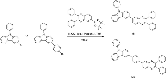
The detailed synthetic routes and chemical structures of bipolar host materials are shown in Scheme 1. The synthesis of M1 and M2 was realized through Suzuki coupling reaction by reacting 3-bromo-9-phenyl-9H-carbazole or 3-(4-bromophenyl)-9-phenyl-9H-carbazole with 2,3-diphenyl-6-(4,4,5,5-tetramethyl-1,3,2-dioxaborolan-2-yl)quinoxaline, respectively in high yields (over 75%). Both two compounds were confirmed by high-resolution mass spectra and nuclear magnetic resonance spectra (shown in ESI†). Under a nitrogen atmosphere, using the TGA and DSC to characterize the thermal properties of compounds M1 and M2. As shown in Fig. 1 and Table 1, the onset decomposition temperature (Td, corresponding to 5% weight loss) according to the TGA data is 321 °C for M1 and is 415 °C for M2. We obviously found that the endothermic glass transition temperature (Tg) for M1 and M2 is determined to be 176 °C and 218 °C by analyzing the DSC traces, indicating M1 and M2 compounds are suitable for developing OLEDs by thermal evaporation technology. Owing to its much more steric structure of the molecule, the host M2 shows obviously both high Tg and Td values. The relatively high thermal stabilities of the host materials are benefit for improving the morphology of the film and lifetime of the device by suppressing the phase separation and crystallization during the operation process of device.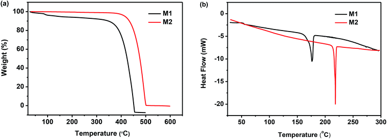 | ||
| Fig. 1 The thermogravimetric (a) and differential scanning calorimetry (b) analysis of bipolar host materials M1 and M2. | ||
| Compound | λabsmax/λonseta [nm] | λemmaxa [nm] | λphosb [nm] | Egc [eV] | ETd [eV] | Eonset [V] | HOMOe [eV] | LUMOf [eV] | Tdg [°C] | Tgh [°C] |
|---|---|---|---|---|---|---|---|---|---|---|
| a Measured in toluene at room temperature.b Measured in toluene at 77 K.c Calculated by the equation EOptg = 1240/λemmax.d Calculated by the first peak of phosphorescence spectra measured at 77 K, ET = 1240/λphos.e Calculated by the equation EHOMO = −4.4 − Eoxonset.f Calculated by the equation ELUMO = EHOMO + Eg.g Measured by TGA.h Measured by DSC. | ||||||||||
| M1 | 247, 298, 387 | 493 | 553 | 2.51 | 2.24 | 1.20 | −5.60 | −3.09 | 321 | 176 |
| M2 | 254, 303, 378 | 518 | 553 | 2.39 | 2.24 | 1.20 | −5.60 | −3.21 | 415 | 218 |
Photophysical properties
The absorption and emission properties of M1 and M2 were investigated in toluene. As depicted in Fig. 2a, the absorption of M1 and M2 exhibits bands in the range from 250 to 430 nm (247, 298, 387 nm for M1; 254, 303, 378 nm for M2), attributed to the π–π* electronic transition of the quinoxaline and carbazole unit.33,34,40–42 M1 and M2 show almost the same absorption spectra in spite of the larger π-electron conjugation of compound M2, implying that the introduction of the phenyl spacer almost has little effect on the absorption properties of these donor–acceptor systems.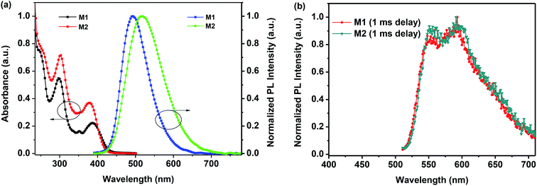 | ||
| Fig. 2 (a) UV-Vis absorption and PL spectra of the compounds M1 and M2 in toluene at 297 K; (b) phosphorescence spectra of the compound M1 and M2 at 77 K. | ||
However, quite different from their absorption properties, two compounds exhibited the different maximum emission wavelength (λemmax = 493 nm for M1; λemmax = 518 nm for M2) in toluene at room temperature, as depicted in Fig. 2a and Table 1. The slight red shifted in the emission of M2 could be attributed to the larger π-electron conjugation. The compounds M1 and M2 exhibited sky-blue or green fluorescence with energy gap of 2.51 and 2.39 eV in toluene, implying that the π-electron conjugation and co-planarity of molecule have been tuned by the phenyl spacer between functionalized quinoxaline moiety and carbazole moiety. In addition, the low temperature phosphorescence spectra of the compound M1 and M2 were also recorded at 77 K to calculate the triplet energies. As shown in the Fig. 2b, the low temperature phosphorescence spectra of both compounds were almost the same. The maximum emission of the phosphorescence spectra was at the wavelength of 553 nm. The triplet energy levels were calculated by the first emission peak of the low-temperature phosphorescence spectra and were determined to be 2.24 eV, which is suitable for the red OLEDs.24 In addition, at the 77 K, we can observe the electronic transitions between the T1 substates (substates III, II, I) and the ground state S0. From the intensity distribution, it can be concluded that the radiative transition from the lowest substate I to the ground state S0 is largely forbidden, while the transitions from the two higher-lying substates III and II to the ground state are significantly more allowed.
Electrochemical properties
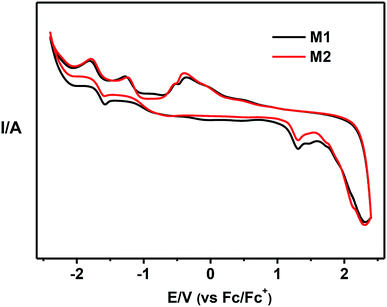
As depicted in Fig. 3, using a standard three-electrode electrochemical cell in an electrolyte solution, the electrochemical behavior of compounds M1 and M2 was investigated by cyclic voltammetry. The energy level of the highest occupied molecular orbital (HOMO) for M1 and M2 were calculated to be both −5.60 eV from the onset potentials of oxidation peak, while the energy level of the lowest unoccupied molecular orbital (LUMO) of these host materials were determined to be −3.09 and −3.21 eV according to the band gap energy (Eg) and HOMO energy level. The data of Eg and HOMO/LUMO energy levels were listed in Table 1. The same HOMO levels of both compounds can be explained by sharing the same electron-donor carbazole group, which indicated that the phenyl spacer between the functionalized quinoxaline moiety and carbazole moiety has no effect on the HOMO levels. However, the LUMO energy of compound M1 (−3.09 eV) were higher than that of M2 (−3.21 eV), implying that the phenyl spacer have evident influence on the LUMO of these donor–acceptor systems.40–42Red phosphorescent OLEDs
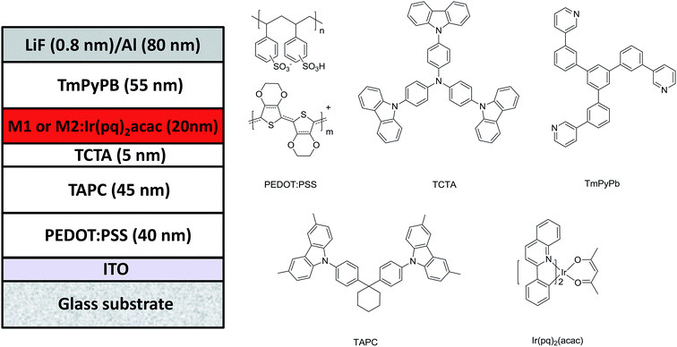
Considering the triplet energy levels (2.24 eV) of M1 and M2 is suitable for red OLEDs, to order to prove their potential application in OLEDs, two doped device of ITO/40 nm-poly(3,4-ethylenedioxythiophene):poly(styrenesulfonate) (PEDOT:PSS) layer/45 nm-di-(4-(N,N-di-p-tolyl-amino)-phenyl)cyclohexane (TAPC) layer/5 nm-4,4′,4′′-tris(carbazol-9-yl)triphenylamine (TCTA) layer/20 nm-hosts: 5% wt bis(2-phenylquinolinato)-acetylacetonate iridium(III) (Ir(pq)2acac) layer/55 nm-1,3,5-tri((3-pyridyl)-phen-3-yl)benzene (TmPyPB) layer/0.8 nm-lithium fluoride (LiF) layer/80 nm-aluminum (Al) layer were fabricated by vacuum thermal deposition, where hosts are M1 and M2, corresponding to the device R1 and R2, respectively. The device structure and organic molecules used in device fabrication are displayed in Fig. 4. In two red devices, different function materials were chosen on the basis of knowing the energy level of materials, and the thickness of different layers was decided by combining the reported relevant literature and mobility of materials.4,6,25 In these devices, ITO was used as an anode; the LiF/Al layers were employed as a composite cathode; 40 nm-thick PEDOT:PSS layer was used as the hole-injection layer; 45 nm-thick TAPC layer was used as the hole transporting layer; 5 nm-thick TCTA layer was used as the exciton blocking layer and 55 nm-thick TmPyPB layer as the electron transport layer. From the energy level diagram of two red devices in Fig. S1 in ESI,† we can see that TCTA and TmPyPB can effectively limit carrier recombination zone and generated exciton in EML because of the big LUMO energy barriers of 0.69 eV and 0.81 eV at TCTA/M1 and M2 interface, a big HOMO energy barrier of 1.20 eV at M1 or M2/TmPyPB interface, and a high triplet levels for TCTA (2.68 eV) and TmPyPB (2.70 eV) than both M1 (2.24 eV) and M2 (2.24 eV).27 Thus, theoretically, both devices R1 and R2 can well reveal the EL performance of compounds M1 and M2.Fig. 5a depicts the normalized EL spectra of M1- and M2-based devices at a voltage of 6 V. Clearly, both M1- and M2-based devices emit red light, and the EL spectra for two devices are almost completely overlapping with the same peak at 594 nm, and CIE coordinates are (0.575, 0.391) and (0.576, 0.389) for M1- and M2-based devices, respectively. These are well consistent to the emission characteristic of emitter Ir(pq)2acac. Meanwhile, from Fig. S2 in ESI,† it is found that there is almost no EL color shift vary at a wide voltage range of 5–8 V for two red devices, which indicates (i) the carrier recombination zone and exciton are well confined in the red EML; and the energy in M1 and M2 hosts can be effectively transferred to Ir(pq)2acac when Ir(pq)2acac is doped in M1 and M2 hosts for two red device. The above result preliminarily proved the feasibility of compounds M1 and M2 as hosts for red OLEDs.
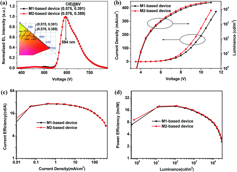 | ||
| Fig. 5 Normalized EL spectra and CIE coordinates at 6 V (a), J–V–L (b), CE–J (c), and PE–L (d) characteristic curves for the M1- and M2-based red devices. | ||
In fact, the high EL performance for both M1- and M2-based devices further demonstrate that both M1 and M2 are excellent host materials for red phosphorescent OLEDs. For example, as shown in Fig. 5b, both M1- and M2-based devices show a relatively low turn-on voltage of 3.6 V, and all achieve very high maximum luminance of 28![[thin space (1/6-em)]](https://www.rsc.org/images/entities/char_2009.gif) 619 cd m−2 for device R1 and 28
619 cd m−2 for device R1 and 28![[thin space (1/6-em)]](https://www.rsc.org/images/entities/char_2009.gif) 818 cd m−2 for device R2. From Fig. 5c, d and S3 in ESI,† both M1- and M2-based devices achieve high device efficiency, and the maximum current efficiency (CE), power efficiency (PE), and EQE reach 28.57 cd A−1, 19.95 lm W−1, and 14.66% for M1-based red device and 29.29 cd A−1, 20.45 lm W−1, and 15.07% for M2-based red device. All above results indicate that these diphenylquinoxaline-based bipolar host materials have potential applications for the development of high-performance red OLEDs. In addition, the performance of red OLEDs in this work are much higher than that in the reported results (PE = 20.45 lm W−1, CE = 29.29 cd A−1, EQE = 15.07% vs. PE = 15.4 lm W−1, CE = 21.9 cd A−1, EQE = 12.2%) showing in Fig. S4,† indicating that the connection ways of electron acceptor/donor moieties have great influence on performance of the host materials (Table 2).34
818 cd m−2 for device R2. From Fig. 5c, d and S3 in ESI,† both M1- and M2-based devices achieve high device efficiency, and the maximum current efficiency (CE), power efficiency (PE), and EQE reach 28.57 cd A−1, 19.95 lm W−1, and 14.66% for M1-based red device and 29.29 cd A−1, 20.45 lm W−1, and 15.07% for M2-based red device. All above results indicate that these diphenylquinoxaline-based bipolar host materials have potential applications for the development of high-performance red OLEDs. In addition, the performance of red OLEDs in this work are much higher than that in the reported results (PE = 20.45 lm W−1, CE = 29.29 cd A−1, EQE = 15.07% vs. PE = 15.4 lm W−1, CE = 21.9 cd A−1, EQE = 12.2%) showing in Fig. S4,† indicating that the connection ways of electron acceptor/donor moieties have great influence on performance of the host materials (Table 2).34
| Device | Host | Voltagea (V) | Maximum | CIEc [x, y] | |||
|---|---|---|---|---|---|---|---|
| CE [cd A−1] | PE [lm W−1] | EQE [%] | Lb (cd m−2) | ||||
| a Voltage at a luminance of >1 cd m−2.b L is the abbreviation of luminance.c Measured from the EL spectra at 6 V. | |||||||
| R1 | M1 | 3.6 | 28.57 | 19.95 | 14.66 | 28![[thin space (1/6-em)]](https://www.rsc.org/images/entities/char_2009.gif) 619 619 |
(0.575, 0.391) |
| R2 | M2 | 3.6 | 29.29 | 20.45 | 15.07 | 28![[thin space (1/6-em)]](https://www.rsc.org/images/entities/char_2009.gif) 818 818 |
(0.576, 0.389) |
Conclusion
To conclude, two novel quinoxaline-based bipolar host materials have been rational design and prepared successfully via the Suzuki coupling reaction in high yields for application in red phosphorescent OLEDs. By incorporating the diphenylquinoxaline and carbazole unit as the electron donor and acceptor, meanwhile, the phenyl spacer between the functionalized quinoxaline moiety and carbazole moiety is also introduced to investigate its influence on their photophysical properties. Their thermal, photophysical and electrochemical properties were investigated and discussed in details. The red phosphorescent OLEDs with M1 and M2 as host were fabricated, and it is found both M1 and M2 hosts-based red devices exhibit the outstanding electroluminescent performance. For example, two red devices all realize good red emission with peak at 594 nm, and the maximum luminance and external quantum efficiency reach 28![[thin space (1/6-em)]](https://www.rsc.org/images/entities/char_2009.gif) 619 cd m−2 and 14.66% for M1-based device and 28
619 cd m−2 and 14.66% for M1-based device and 28![[thin space (1/6-em)]](https://www.rsc.org/images/entities/char_2009.gif) 818 cd m−2 and 15.07% for M2-based device, indicating that compounds M1 and M2 synthesized in this work have the potential applications in the development of high performance red and white OLEDs.
818 cd m−2 and 15.07% for M2-based device, indicating that compounds M1 and M2 synthesized in this work have the potential applications in the development of high performance red and white OLEDs.
Conflicts of interest
There are no conflicts to declare.Acknowledgements
Zilong Feng and Zhixiang Gao contributed equally to this work. The authors are grateful for the financial support of the National Natural Science Foundation of China (21872088, 11874245), Shanxi Province Science and Technology Key Project (201703D121037-2), Datong City Science and Technology Research Project (2018018).References
- C. W. Tang and S. A. VanSlyke, Appl. Phys. Lett., 1987, 51, 913–915 CrossRef CAS.
- S. Reineke, F. Lindner, G. Schwartz, N. Seidler, K. Walzer, B. Lussem and K. Leo, Nature, 2009, 459, 234–238 CrossRef CAS PubMed.
- Y. Chang, Y. Song, Z. Wang, M. Helander, J. Qiu, L. Chai, Z. Liu, G. Scholes and Z. Lu, Adv. Funct. Mater., 2013, 23, 705–712 CrossRef CAS.
- Y. Miao, K. Wang, L. Gao, H. Wang, F. Zhu and B. Xu, J. Mater. Chem. C, 2018, 6, 9811–9820 RSC.
- H. Sasabe and J. Kido, J. Mater. Chem. C, 2013, 1, 1699–1707 RSC.
- P. Tao, Y. Miao, H. Wang, B. Xu and Q. Zhao, Chem. Rec., 2018, 18, 1–32 CrossRef.
- V. Sree, A. Maheshwaran, H. Kim, H. Park, Y. Kim, J. Lee, M. Song and S. Jin, Adv. Funct. Mater., 2018, 28, 1804714 CrossRef.
- X. Tang, X. Liu, Z. Jiang and L. Liao, Adv. Funct. Mater., 2019, 29, 1807541 CrossRef.
- T. H. Han, Y. Lee, M. R. Choi, S. H. Woo, S. H. Bae, B. H. Hong, J. H. Ahn and T. W. Lee, Nat. Photonics, 2012, 6, 105–110 CrossRef CAS.
- H. Uoyama, K. Goushi, K. Shizu, H. Nomura and C. Adachi, Nature, 2012, 492, 234–238 CrossRef CAS PubMed.
- Y. Miao, K. Wang, L. Gao, B. Zhao, Z. Wang, Y. Zhao, A. Zhang, H. Wang, Y. Hao and B. J. Xu, J. Mater. Chem. C, 2018, 6, 1853–1862 RSC.
- C. L. Ho and W. Y. Wong, Coord. Chem. Rev., 2013, 257, 1614–1649 CrossRef CAS.
- L. Ying, C. L. Ho, H. B. Wu, Y. Cao and W. Y. Wong, Adv. Mater., 2014, 26, 2459–2473 CrossRef CAS PubMed.
- X. L. Yang, G. J. Zhou and W. Y. Wong, J. Mater. Chem. C, 2014, 2, 1760–1778 RSC.
- P. Tao, Y. Zhang, J. Wang, L. Wei, H. Li, X. Li, Q. Zhao, X. Zhang, S. Liu, H. Wang and W. Huang, J. Mater. Chem. C, 2017, 5, 9306–9314 RSC.
- R. Ding, J. Feng, F. X. Dong, W. Zhou, Y. Liu, X. L. Zhang, X. P. Wang, H. H. Fang, B. Xu, X. B. Li, H. Y. Wang, S. Hotta and H. B. Sun, Adv. Funct. Mater., 2017, 27, 1604659 CrossRef.
- J. Lin, Y. Wang, P. Gnanasekaran, Y. Chiang, C. Yang, C. Chang, S. Liu, G. Lee, P. Chou, Y. Chi and S. Liu, Adv. Funct. Mater., 2017, 27, 1702856 CrossRef.
- M. A. Baldo, D. F. O'Brien, Y. You, A. Shoustikov, S. Sibley, M. E. Thompson and S. R. Forrest, Nature, 1998, 395, 151–154 CrossRef CAS.
- Y. R. Sun, N. C. Giebink, H. Kanno, B. W. Ma, M. E. Thompson and S. R. Forrest, Nature, 2006, 440, 908–912 CrossRef CAS PubMed.
- J. Lee, H. F. Chen, T. Batagoda, C. Coburn, P. I. Djurovich, M. E. Thompson and S. R. Forrest, Nat. Mater., 2016, 15, 92–98 CrossRef CAS PubMed.
- W. Y. Wong and L. J. Ho, J. Mater. Chem., 2009, 19, 4457–4482 RSC.
- W. Y. Wong and C. L. Ho, Coord. Chem. Rev., 2009, 253, 1709–1758 CrossRef CAS.
- P. Tao, Q. Zhao, S. Jing, J. Wang, Z. Lv, L. Chen and H. Wang, Chin. J. Lumin., 2013, 34, 816–823 CrossRef CAS.
- P. Tao, W. Li, J. Zhang, S. Guo, Q. Zhao, H. Wang, B. Wei, S. Liu, X. Zhou, Q. Yu, B. Xu and W. Huang, Adv. Funct. Mater., 2016, 26, 881–894 CrossRef CAS.
- Y. Miao, P. Tao, L. Gao, X. Li, L. Wei, S. Liu, H. Wang, B. Xu and Q. J. Zhao, J. Mater. Chem. C, 2018, 6, 6656–6665 RSC.
- C. Fan and C. L. Yang, Chem. Soc. Rev., 2014, 43, 6439–6469 RSC.
- Y. Miao, K. Wang, L. Gao, B. Zhao, H. Wang and F. J. Zhu, J. Mater. Chem. C, 2018, 6, 8122–8134 RSC.
- J. J. Guo, X. L. Li, H. Nie, W. W. Luo, S. F. Gan, S. M. Hu, R. R. Hu, A. J. Qin, Z. J. Zhao, S. J. Su and B. Z. Tang, Adv. Funct. Mater., 2017, 27, 1606458 CrossRef.
- L. Gao, P. Tao, Y. Miao, W. Jia, Y. Zhao, H. Wang and B. Xu, Tetrahedron Lett., 2018, 59, 2095–2098 CrossRef CAS.
- Y. Miao, K. Wang, B. Zhao, L. Gao, Y. Wang, H. Wang, B. Xu and F. J. Zhu, J. Mater. Chem. C, 2017, 5, 12474–12482 RSC.
- X. Cai and S. Su, Adv. Funct. Mater., 2018, 28, 1802558 CrossRef.
- H. Li, P. Tao, Y. Xu, X. Zhang, S. Liu and Q. Zhao, Tetrahedron Lett., 2018, 59, 1748–1751 CrossRef CAS.
- C. H. Fan, P. P. Sun, T. H. Su and C. H. Cheng, Adv. Mater., 2011, 23, 2981–2985 CrossRef CAS PubMed.
- M. Hu, Q. Xu, Y. Jiang, H. Mu, L. Gao, P. Hu, J. Huang and J. Su, Dyes Pigm., 2018, 150, 185–192 CrossRef CAS.
- Y. Miao, P. Tao, K. Wang, H. Li, B. Zhao, L. Gao, H. Wang, B. Xu and Q. Zhao, ACS Appl. Mater. Interfaces, 2017, 9, 37873–37882 CrossRef CAS PubMed.
- P. Tao, Y. Miao, Y. Zhang, K. Wang, H. Li, L. Li, X. Li, T. Yang, Q. Zhao, H. Wang, S. Liu, X. Zhou, B. Xu and W. Huang, Org. Electron., 2017, 45, 293–301 CrossRef CAS.
- P. Tao, Y. Miao, K. Wang, H. Li, Q. Zhao, H. Wang, J. Li, B. Xu and W. Huang, Tetrahedron Lett., 2017, 58, 3598–3601 CrossRef CAS.
- Z. Feng, P. Tao, L. Zou, P. Gao, Y. Liu, X. Liu, H. Wang, S. Liu, Q. Dong, J. Li, B. Xu, W. Huang, W. Wong and Q. Zhao, ACS Appl. Mater. Interfaces, 2017, 9, 28319–28330 CrossRef CAS PubMed.
- Y. Miao, K. Wang, B. Zhao, L. Gao, P. Tao, X. Liu, Y. Hao, H. Wang, B. Xu and F. Zhu, Nanophotonics, 2018, 7, 295–304 CAS.
- W. Li, J. Y. Li, D. Liu and Q. Jin, ACS Appl. Mater. Interfaces, 2016, 8, 22382–22391 CrossRef CAS PubMed.
- H. Xu, P. Sun, K. Wang, J. Li, F. Wang, Y. Miao, H. Wang, B. Xu and W. Wong, J. Mater. Chem. C, 2017, 5, 4455–4462 RSC.
- K. Wang, P. Sun, H. Xu, J. Li, F. Wang, Y. Miao, T. Yang, H. Wang, B. Xu and W. Wong, Dyes Pigm., 2017, 143, 25–32 CrossRef CAS.
Footnotes |
| † Electronic supplementary information (ESI) available. See DOI: 10.1039/c9ra01149h |
| ‡ These authors contributed equally to this work. |
| This journal is © The Royal Society of Chemistry 2019 |

