 Open Access Article
Effect of on-line stretching treatment on the structure and performance of polyvinyl chloride hollow fiber membranes
Fang Lu,
Hailiang Liu *,
Changfa Xiao,
Xinya Wang,
Kaikai Chen and
Heng Huang
State Key Laboratory of Separation Membranes and Membrane Processes, National Center for International Joint Research on Separation Membranes, Tianjin Polytechnic University, Tianjin 300387, China. E-mail: liuhl@tjpu.edu.cn; Tel: +86-22-8395-5397
First published on 26th February 2019
Abstract
In this work, polyvinyl chloride (PVC) hollow fiber membranes were prepared via a melt-spinning method and on-line stretching treatment. Gamma-butyrolactone (GBL) and epoxidized soybean oil (ESO) were selected as the solvent and the thermal stabilizer, respectively. The effects of on-line stretching treatment on the membrane structure and performance were characterized by means of morphology, surface roughness, pore size distribution, permeation performance and so on. The morphology showed that the prepared PVC hollow fiber membrane belonged to a homogeneous membrane. The on-line stretching treatment decreased the roughness of the inner surface and the outer surface, but it increased the water contact angle, mean pore size, porosity and pure water flux. Meanwhile, the pore size distribution range remained stable and narrow. The rejection of Direct Black 19 particles was higher than 90% when it approached a steady value. This type of membrane filtration was a deep intercept. Furthermore, the tensile strength increased with the increment of stretching ratio, and the elongation at break showed the opposite trend. The biggest tensile strength could be obtained as the stretching ratio reached 3.0 and was 23.89 MPa.
1. Introduction
Membrane separation technology has the functions of separation, concentration, purification and rectification.1 Compared with traditional separation technology, membrane separation technology exhibits enormous advantages, such as consuming less energy, easy operation, simple devices and so on.2 Membrane materials, which are the core of the membrane separation process, have great influence on the performance of the membrane. Common membrane materials include polyvinylidene fluoride (PVDF), polyether sulfone (PES), polyacrylonitrile (PAN), cellulose acetate (CA) and so on.3 Polyvinyl chloride (PVC) is widely applied in membrane separation technology because of its low cost, high resistance to acids, alkalis and solvents, and good salt corrosion resistance.4PVC is an amorphous polymer and is easily dissolved in a variety of polar solvents with low crystallinity, and its decomposition temperature is lower than its melting temperature. Therefore, PVC membranes are usually prepared by the non-solvent induce phase separation (NIPS) method.5 For example, Ghazanfari et al.6 added alumina into PVC membranes, which could be used in membrane bioreactors. The results showed that the prepared membrane with 3 wt% alumina exhibited terrific permeation and anti-fouling performance. Moreover, Zhuang et al.7 prepared a poly(VC-co-PEGMA)/PVC blend membrane by the NIPS method. The results reflected that a considerable improvement in anti-fouling propensity could be achieved when the co-polymer/PVC blending ratio was greater than 1![[thin space (1/6-em)]](https://www.rsc.org/images/entities/char_2009.gif) :
:![[thin space (1/6-em)]](https://www.rsc.org/images/entities/char_2009.gif) 2.
2.
However, the NIPS method requires a lot of solvent during the membrane preparation process, which leads to high costs and environmental pollution.8 Although the prepared membrane has high porosity and narrow pore size distribution, the mechanical strength of the membrane hardly adapts to harsh environments, such as membrane bioreactor (MBR) systems. Therefore, the melt-spinning method has received extensive attention. This method decreases the use of solvents and has a high efficiency in preparing membranes. In general, the melting point of the polymer is lower than the decomposition temperature, and the polymer can be melted to form a thermally stable melt, then it can be applied to prepare membranes by the melt-spinning method.9 However, there are few studies that report PVC membrane fabrication by the melt-spinning method, because PVC resin is easily decomposed during the preparation process due to its low decomposition temperature. It is well known that a plasticizer can improve the fluidity of PVC resin below its melting temperature and reduce its glass transition temperature.10 Furthermore, thermal stabilizers can improve the thermal stability of PVC resin and allow the PVC resin to be processed by melt-spinning process at high temperature.
In our previous study,11 dioctyl phthalate (DOP) as a plasticizer was used to fabricated PVC hollow fiber membranes. But the resistance to testing pressure of the obtained membrane was poor in the application. On the one hand, the DOP that existed in the PVC hollow fiber membranes would slowly escape which might cause secondary pollution and, on the other hand, the extracted membranes could shrink on the macro-level, and their pore size could become large but the flux decreased. In some studies,12,13 gamma-butyrolactone (GBL) was regarded as a highly safe and environmentally friendly water-soluble solvent because it is miscible with water, so the membrane that uses GLB as a solvent can be washed with water, and the surface of the membrane is smooth without shrinkage. As one of the solvents for PVC resin, the interaction force between GBL and PVC resin is weak compared with that of conventional solvents, such as N,N-dimethylacetamide (DMAc), N,N-dimethylformamide (DMF), dimethyl sulfoxide (DMSO) and so on.14 Moreover, the existence of an ester group in GBL can plasticize PVC resin to a certain extent, so as to change the aggregation state structure of PVC resin and improve the membrane strength. Furthermore, the weak interaction force between GBL and PVC resin can reduce the decomposition of PVC at high processing temperatures. Thus, GBL as the processing agent can replace the DOP plasticizer in the preparation process, and reduce the processing costs.
In this work, a PVC hollow fiber membrane has been prepared via the melt-spinning method. PVC as the polymeric material, GBL as the solvent, epoxidized soybean oil (ESO) as the thermal stabilizer and a composite powder as the pore-creating agent were applied in this work. On-line stretching treatment was adopted to adjust the morphology and performance of the membrane. The effects of different on-line stretching ratios on the structure and performance of the obtained PVC hollow fiber membrane were researched.
2. Experimental
2.1 Materials
Polyvinyl chloride (PVC, fiber grade, DG-1000k) with average degree polymerization 1030 and gamma-butyrolactone (GBL, Analytical Reagent) were purchased from Tianjin Dagu Chemical Factory (Tianjin, China) and Tianjin Guangfu Fine Chemical Research Institute (Tianjin, China), respectively. The composite powder (a mixture of nanosized KCl and SiO2 particles) was provided by Tianjin Motian Membrane Engineering & Technology Co., Ltd (Tianjin, China). Epoxidized soybean oil (ESO, epoxy value > 6) was supplied by Shanghai Wenhua Chemical Pigments Co., Ltd (Shanghai, China). Poly(ethylene glycol) (PEG, Chemically Pure, Mw = 20![[thin space (1/6-em)]](https://www.rsc.org/images/entities/char_2009.gif) 000) was bought from Tianjin Kermel Chemical Reagent Co., Ltd (Tianjin, China). Direct Black 19 (DB 19) was obtained from Tianjin Jili Chemical Plant (Tianjin, China).
000) was bought from Tianjin Kermel Chemical Reagent Co., Ltd (Tianjin, China). Direct Black 19 (DB 19) was obtained from Tianjin Jili Chemical Plant (Tianjin, China).
2.2 Membrane fabrication and treatment
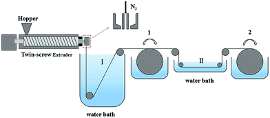
The PVC hollow fiber membrane was prepared by the melt-spinning method and on-line stretching treatment. PVC, GBL and the composite powder were mixed uniformly in a specific weight ratio. Then the mixture was fed into a twin-screw extruder machine and extruded. The extrudate was solidified in water bath I at 25 °C at first and rolled up in the first winding roller after that. Next, it was stretched on-line in water bath II at 80 °C. Afterwards, the membranes were treated in the second winding roller at a 50 °C heat setting so as to maintain the membrane structure. Finally, the membranes were extracted in a water bath for more than 2 days in order to get rid of the annexing agent. The on-line stretching ratios that were used were 1.0, 1.5, 2.0, 2.5, and 3.0, and these membranes were named M1, M2, M3, M4 and M5, respectively. A schematic diagram of the PVC hollow fiber membrane preparation is shown in Fig. 1, and the composition and spinning conditions are shown in Table 1.| Spinning conditions | Value | |||
|---|---|---|---|---|
| PVC/GBL/ESO/PEG20000/composite powder/wt% | 31.00/11.00/5.00/5.00/48.00 | |||
| Extrusion machine and spinneret temperature/°C | 155.00 | |||
| Bore fluid | N2 | |||
| Water bath I T/°C | 25.00 ± 5.00 | |||
| Water bath II T/°C | 80.00 ± 5.00 | |||
| Air gap/cm | 2.00 | |||
| Extrusion speed/m min−1 | 4.33 | |||
| Take up speed 1/m min−1 | 6.28 | |||
| Spinneret draw ratio | 1.45 | |||
| Take up speed 2/m min−1 | 9.42 | 12.56 | 15.70 | 18.84 |
2.3 Membrane characterizations
The cross-section and surface morphologies of the PVC hollow fiber membranes were characterized by a scanning electron microscope (Hitachi S4800, HITACHI, Japan). A true color confocal microscope (Axio CSM 700, ZEISS, Germany) was used to investigate the surface roughness and 3D images of the PVC hollow fiber membranes. The water contact angle of each sample was measured by a contact angle meter (DSA100, KRUSS, Germany) at room temperature. An electronic tensile testing machine (JBDL-200N, Jing Bo Machinery Co., Ltd., China) was applied to measure the mechanical properties of the membrane at room temperature. A dry-wet weight method was introduced to calculate the membrane porosity.15–17 A capillary flow porometer (3H-2000PB, Beshide Instrument Technology Co., Ltd., China) was used to assess the pore size and its distribution.2.4 Microfiltration test
The textile dye wastewater of DB 19 was used to investigate the microfiltration performance of the PVC hollow fiber membranes. For fear of the compacting effect of the membrane, pure water was fed by applying 0.1 MPa pressure for 45 min before the microfiltration experiments. DB 19 was added into distilled water and fully stirred to prepare the dye wastewater with a concentration of 1 g L−1 and then the dye solution was fed into the filter system. Finally, the membrane was thoroughly washed for 20 min after the microfiltration experiment.18,19 The concentrations of the dye solution and the filtration solution were measured via a UV spectrophotometer (UV-1901, Beijing Purkinje General Instrument Co., Ltd., China) at a wavelength of 645 nm. The permeate flux (J) and rejection (R) of the membranes were calculated by eqn (1) and (2), respectively.
 | (1) |
 | (2) |
By measuring the changes of flux during the total microfiltration process, the flux recovery rate (FRR), the total flux decline ratio (DRt), the reversible flux decline ratio (DRr), and the irreversible flux decline ratio (DRir) can be obtained, which can be calculated according to eqn (3)–(6):20–22
 | (3) |
 | (4) |
 | (5) |
 | (6) |
3. Results and discussion
3.1 Morphologies of the PVC hollow fiber membranes
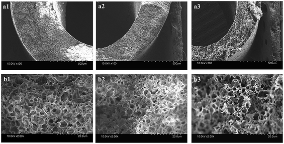
The cross-section morphologies of the prepared PVC hollow fiber membranes are shown in Fig. 2, and the inner diameter, outer diameter and wall thickness of the PVC hollow fiber membranes are listed in Table 2. As shown in Fig. 2, the structure of the PVC hollow fiber membranes obtained by the melt-spinning process is different from the membrane prepared by the phase inversion method,23 and it exhibited no obviously dense surface and revealed a homogeneous sponge-like structure. It could be explained that the composite pore-creating agent was uniformly dispersed in the polymer system during the membrane preparation process. After the melt trickles were extruded from the spinneret into the coagulation bath and were solidified, the soluble composite pore-creating agent was dissolved which resulted in the formation of the micropore structure. As shown in Fig. 2 and Table 2, the inner diameter, outer diameter and wall thickness of the obtained membranes were reduced as the stretching ratio increased. These variations were related to the motion of the macromolecular chains which were aggravated at 80 °C in the stretching process. Then, the intramolecular stress caused by tensile deformation was eliminated during the fixed-length and heat-setting process at 50 °C. At the same time, the PVC macromolecular chains were frozen when the temperature was lower than the glass transition temperature (Tg) of the PVC hollow fiber membrane which was caused by the extraction of the GBL from the membranes. Thus, the deformation recovery of the membrane was interrupted and the morphology and structure of the PVC hollow fiber membrane changed.| Membrane | OD/mm | ID/mm | Wall thickness/mm |
|---|---|---|---|
| M1 | 2.35 | 1.36 | 0.495 |
| M2 | 2.20 | 1.19 | 0.505 |
| M3 | 2.00 | 1.16 | 0.420 |
| M4 | 1.90 | 1.12 | 0.390 |
| M5 | 1.85 | 1.13 | 0.360 |
Fig. 3 shows the inner and outer surface morphologies of the PVC hollow fiber membranes. Fig. 3(a) shows the inner surface morphology of the membrane, and Fig. 3(b) shows the outer surface morphology of the membrane. As can be seen from Fig. 3(a1), the inner surface of the membrane was composed of larger circular pores, smaller striped pores and circular pores. As shown in Fig. 3(b1), the outer surface of the membrane was composed of large oval pores, and the pore size of the outer surface was significantly larger than that of the inner surface. The larger circular and oval pores on the membrane surface were formed by the dissolution of the composite pore-creating agent. Moreover, the smaller striped pores and circular pores were formed by the dissolution of PEG and GBL, respectively. These findings were mainly caused by the difference in temperature between the inner and outer surfaces during the preparation of the PVC hollow fiber membranes. As the melt trickles were extruded by the twin-screw extruder machine and then placed in the air bath and water bath, the outer surface of the extrudate was partially cured due to the exposure to the air bath. However, the curing speed of the inner surface was postponed because of the introduction of heated nitrogen gas into the inner core of the PVC hollow fiber membranes. During this process, the incompletely solidified outer surface was stretched along the drawing direction under the effect of winding traction and the oval-shaped pores were formed. Thus, the pore size of the outer surface was significantly larger than that of the inner surface.
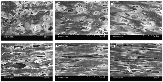 | ||
| Fig. 3 The surface morphology of the PVC hollow fiber membranes ((a) inner surface, and (b) outer surface; (a1 and b1) M1, (a2 and b2) M3, and (a3 and b3) M5). | ||
It also can be seen that the surface pores of the membrane gradually became narrow with an increase in stretching ratio, and the changes to the pore size of the outer surface were more obvious, as shown in Fig. 3. These changes could be attributed to the use of the composite pore-creating agent uniformly dispersed in the PVC hollow fiber membrane, which was not completely washed and acted as the interfacial pore forming agent during the on-line stretching process. The shape of the pores changed when the membrane matrix was deformed along the direction of external force. The pores of the inner surface were changed from circle to oval, while the oval pores of the outer surface became longer and narrower. The deformation of the membrane occurred instantaneously when it was immersed in the hot water bath at 80 °C. The deformation of the outer surface was more obvious because the temperature gradient formed from the outside to the inside of the membrane wall.
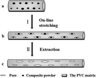
A schematic diagram of the on-line stretching pore formation process of the PVC hollow fiber membranes is shown in Fig. 4. As can be seen from Fig. 4, the composite powder was evenly encapsulated by the polymer matrix when the nascent hollow fiber membrane (Fig. 4(a)) was extruded from the spinneret. During the on-line stretching process (I), external force caused the nascent membrane to deform along the direction of the external force while the nascent membrane entered the hot water bath at 80 °C. But the composite powder was the rigid inorganic substance which led to lag behind the matrix upon deformation, thereby leading to the formation of interface micropores (Fig. 4(b)). During the process, the external force applied on the nascent membrane became strong with an increase in stretching ratio, then the interface pores became narrower. At the same time, the presence of the composite powder could effectively reduce the closure of the pores on the membrane surface. After the extraction process (II), the soluble composite powder was completely washed out and the membrane pore structure was formed which is shown in Fig. 4(c).
3.2 Surface roughness of the PVC hollow fiber membranes
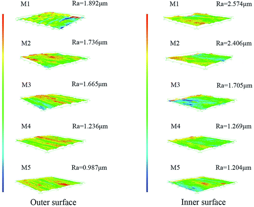
Fig. 5 shows the inner and outer surface roughness of the obtained membranes. It can be observed that the roughness of the inner and outer surfaces of the membrane showed a decreasing trend with the increment of stretching ratio, and the roughness of the membrane inner surface was larger than that of the membrane outer surface at the same stretching ratio. This conclusion was also in agreement with the result of the surface morphology of the PVC hollow fiber membranes shown in Fig. 3. The outer surface was smoother than the inner surface because it rapidly solidified when it came into contacting with the water coagulation bath at room temperature. But the inner surface contacted heated nitrogen gas, so the curing speed was slower and formed more pores which led to an increase in the inner surface roughness. Under external force, the nascent membrane was deformed by on-line stretching. The PVC macromolecular chain was orientated under external force at a temperature of 80 °C which made the chain arrangement more regular. These changes made the surface pores become long and narrow which increased the surface smoothness and reduced the surface roughness.In our previous study, the extraction of the plasticizer DOP led to shrinkage in the membrane on the macro-level.22 The shrinkage of the membrane would increase the membrane surface roughness and reduce the uniformity of the membrane. But in this study, based on the use of a water-soluble GBL solvent which would elute slowly during the preparation of the membrane, the pores of the membrane would not shrink during the washing process. In addition, the fixed-length heat-setting process also avoided the shrinkage of the membrane and the extraction process could speed up the dissolution rate of the solvent in the meantime.
3.3 The water contact angle of the PVC hollow fiber membranes
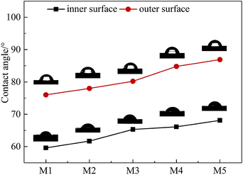
Fig. 6 shows the curve diagram of the water contact angle of the PVC hollow fiber membrane that changed with the stretching ratios. As can be seen, the contact angle of the inner surface was smaller than that of the outer surface, and the contact angle of the inner surface and the outer surface increased with the increment of stretching ratio. This result was associated with the roughness of the membrane surface. For hydrophilic materials, the higher the roughness of the surface, the stronger the hydrophilicity and the smaller the water contact angle.24 The inner surface roughness was significantly larger than that of the outer surface, so the contact angle of the inner surface was smaller than that of the outer surface. With an increase in stretching ratio, the membrane surface became smooth which brought about a decrease in roughness and an increment of water contact angle.3.4 Mechanical properties of the PVC hollow fiber membranes
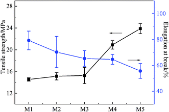
Fig. 7 shows the effects of stretching ratio on the mechanical properties of the PVC hollow fiber membranes. The tensile rate and initial distance between the two fixtures were set at 100 mm min−1 and 50 mm, respectively. From Fig. 7, it can be observed that the tensile strength of the PVC hollow fiber membrane increased with the increment of stretching ratio, but the elongation at break showed an opposite trend. These phenomena could be explained by the fact that the on-line stretching improved the orientation degree of the PVC molecules. The chain segments were compelled to orientate in the stretching process. The orientation degree was increased with an increase in external force. Therefore, the PVC molecular chain arrangement possessed high orderliness and intermolecular force.25 In this study, the tensile strength of M5 could reach 23.89 MPa, while the elongation at break was 55.67%. This demonstrated that the obtained PVC hollow fiber membrane had excellent mechanical properties.3.5 Porosity and pore size distribution of the PVC hollow fiber membranes
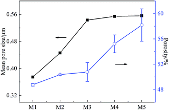
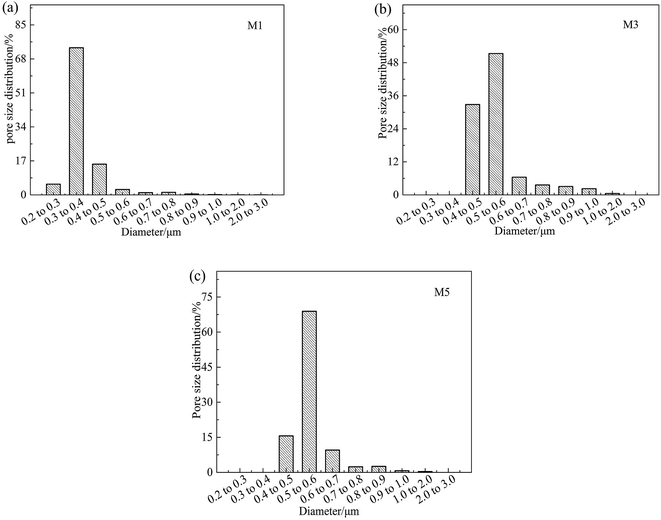
The effects of on-line stretching ratio on the mean pore size and porosity of the PVC hollow fiber membranes are shown in Fig. 8, while the pore size distribution of the PVC hollow fiber membranes is shown in Fig. 9. From Fig. 8, it can be seen clearly that the mean pore size of the PVC hollow fiber membranes becomes larger and the porosity increases after on-line stretching. This is related to the fact that on-line stretching treatment could increase the pore size of the membrane surface and improve the pore connectivity of the membrane cross-section. It also can be found that the mean pore size increased rapidly when the stretching ratio was small (the stretching ratio was less than 2.0). As the stretching ratio increased to 3.0, the mean pore size did not increase obviously. However, the porosity increased continuously. This was because the pores on the membrane surface became longer and narrower when the stretching ratio increased. As the stretching ratio was small, the changes in the pores on the membrane surface were mainly dominated by the increase in pore length (Fig. 3(b1) and (b2)), and this caused the mean pore size to increase rapidly. Nevertheless, the changes in the pores on the membrane surface were mainly dominated by the decrease in pore width (Fig. 3(b3)) when the stretching ratio increased to 3.0. In consequence the mean pore size of the membrane did not increase significantly.Fig. 9 shows the pore size distribution of the prepared PVC hollow fiber membranes. As can be seen from Fig. 9, the pore size distribution of the membrane obtained by on-line stretching was narrow. With the increment of stretching ratio, there was no obvious broadening of the pore size distribution range, which was obviously better than the post-stretching treatment.22,26 In our previous studies, we found that post-stretching treatment led to an increase in both the mean pore size and the pore size distribution range of the membrane, which broadened the pore size distribution range and lessened the rejection accuracy at the same time. It was obviously found that the influence of on-line stretching treatment on the pore size distribution was less than that of post-stretching treatment.
3.6 Permeation properties of PVC hollow fiber membranes
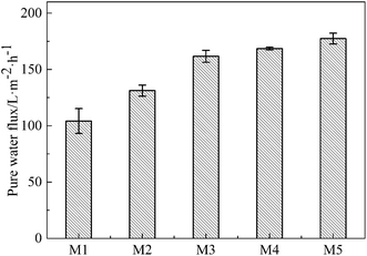
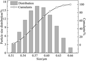
The effects of the on-line stretching ratio on the PWF of the PVC hollow fiber membranes are shown in Fig. 10. From Fig. 10, it is obviously found that the PWF increased with the increment of stretching ratio. This result could be explained as follows: the pores of the membrane surfaces became longer and bigger, while the pore connectivity of the membrane cross-section became better, which increased the mean pore size and porosity of the membrane, and reduced the wall thickness of the membrane. All of these changes decreased the membrane filtration resistance and increased the PWF.27DB 19 was applied to evaluate the microfiltration performance of the obtained membranes and its particle size distribution is shown in Fig. 11. The result showed that the mean particle size was 0.58 μm and the particles were distributed in the range of 0.51–0.66 μm.
At the initial filtration stage, the polymeric membrane had a compaction phenomenon. In order to avoid this phenomenon, pure water was fed for 45 min at 0.1 MPa pressure and a temperature of 20 ± 2 °C to stabilize the membrane structure before the microfiltration experiment and then the dye solution was fed into the filter system.
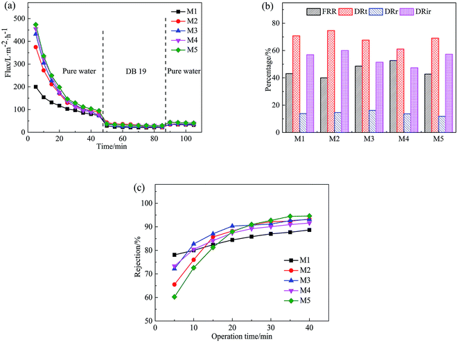
Fig. 12 shows the permeation flux of the PVC hollow fiber membranes, the FRR, DRt, DRr, and DRir values in the DB 19 solution filtration process and the rejection rate of the membranes. Fig. 12(a) shows the variation of permeation flux with operation time for the obtained membranes with different stretching ratios. As can be seen from Fig. 12(a), the first stage was the pre-pressure process, the second stage was dye solution filtration and the third stage was flux recovery. At the first stage, the membrane was compacted under external pressure, and the membrane pore size became smaller. The flux decreased sharply with the extension of time, then the flux stabilized after 45 min. At the second stage, the membrane was polluted by the dye solution during the filtration process. At first, the dye particles were adsorbed or deposited in membrane pores which decreased the filtration flux significantly compared with the PWF. But with the extension of filtration time, the dye particles accumulated on the membrane surface to form a filter cake layer, and the filtration flux of the PVC hollow fiber membranes tended to stabilize. At the third stage, the dye particles accumulated on the surface of the membrane were washed away after washing the membrane module for 20 min, and the PWF was recovered, but the recovery rate was very low. This might be due to the washing process merely removing the filter cake layer which was attached to the membrane surface. However, the contaminants in the membrane pores were hardly removed and could be combined with back washing and chemical cleaning methods.
From Fig. 12(b), it can be seen that the FRR, DRt, DRr and DRir values of the PVC hollow fiber membranes with different stretching ratios had no obvious regularity, and the FRR values ranged from 40% to 60%, the DRt values were higher than 60%, and the DRir values were higher than 45%. The higher the FRR value was and the lower the DRt value was, the better the anti-fouling performance was.28 In this experiment, it can be found that the anti-fouling performance of the obtained membrane was poor and the pollution was difficult to remove by water washing.
As can be seen from Fig. 12(c), the rejection rate of the membrane prepared by the on-line stretching treatment was smaller than that of the un-stretched membrane at the beginning, but it increased rapidly after 20 min and then slowly increased to 90% at 40 min. At this time, the rejection rate of the membrane after on-line stretching was higher than that of the un-stretched membrane. This was mainly because membrane fouling was mainly due to the blockage of the membrane pores by dye particles in the early stage of the filtration experiment, which rapidly increased the filtration resistance and rejection rate of the membrane. In addition, the filter cake layer that was formed by concentration polarization was attached to the membrane surface as time prolonged, therefore the membrane pore size was reduced and the rejection rate increased slowly during the filtration process. Combined with Fig. 12(a)–(c), this type of membrane filtration was a deep intercept for the prepared PVC hollow fiber membrane, which was different from the surface intercept for the membrane prepared by the NIPS method.29,30
4. Conclusions
PVC hollow fiber membranes were fabricated via a melt-spinning method and on-line stretching treatment. The obtained membranes had a homogeneous sponge-like structure. In addition, the surface pores gradually became narrow and long when the stretching ratio increased, and the changes in the pore size of the outer surface were more obvious. The surface of the membrane became smooth with the increment of stretching ratio, and the roughness of the inner surface was larger than that of the outer surface at the same stretching ratio. This result brought about a decrease in hydrophilicity which resulted in an increase in water contact angle in the meantime. The mean pore size, porosity and PWF of the resultant membrane were also controlled by the on-line stretching treatment which made them increase. The pore size distribution range of the prepared membranes was narrow which improved its rejection accuracy. The rejection rate of the PVC hollow fiber membranes to the DB 19 particles was higher than 90% when it approached a steady value. This type of membrane filtration was a deep intercept for the prepared PVC hollow fiber membrane. In addition, the tensile strength increased with an increase in stretching ratio while the elongation at break was opposite. The biggest tensile strength could be obtained as the stretching ratio reached 3.0 and was 23.89 MPa.Conflicts of interest
There are no conflicts of interest to declare.Acknowledgements
The authors gratefully acknowledge the research funding provided by the National Natural Science Foundation of China (51603146, 51673149), the Natural Science Foundation of Tianjin (18JCQNJC72200), the Science & Technology Development Fund of Tianjin Education Commission for Higher Education (2018KJ198), and the Industrial Chain Collaborative Innovation Major Projects of the State Oceanic Administration (BHSF2017-01).References
- M. Elimelech and W. A. Phillip, Science, 2011, 333, 712 CrossRef CAS PubMed.
- C. Charcosset, Desalination, 2009, 245, 214–231 CrossRef CAS.
- H. Strathmann, J. Membr. Sci., 1981, 9, 121–189 CrossRef CAS.
- B. C. Liu, C. Chen and W. Zhang, Desalination, 2012, 307, 26–33 CrossRef CAS.
- Č. Stropnik and V. Kaiser, Desalination, 2002, 145, 1–10 CrossRef.
- D. Ghazanfari, D. Bastani and S. A. Mousavi, Journal of Water Process Engineering, 2017, 16, 98–107 CrossRef.
- Z. Zhuang, S. Rajabzadeh, A. R. Shaikh, Y. Kakihana, W. Z. Ma and H. Matsuyama, J. Membr. Sci., 2016, 514, 537–546 CrossRef.
- H. Strathmann, ACS Symp. Ser., 1985, 269, 165–195 CrossRef CAS.
- J. J. Kim, T. S. Jang, Y. D. Kwon, U. Y. Kim and S. S. Kim, J. Membr. Sci., 1994, 93, 209–215 CrossRef CAS.
- M. A. Semsarzadeh, M. Mehrabzadeh and S. S. Arabshahi, Eur. Polym. J., 2002, 38, 351–358 CrossRef CAS.
- H. L. Liu, C. F. Xiao and X. Y. Hu, Desalin. Water Treat., 2013, 51, 3786–3793 CrossRef CAS.
- Y. L. Zhu, G. W. Zhao, J. Chang, J. Yang, H. Y. Zheng, H. W. Xiang and Y. W. Li, Catal. Lett., 2004, 96, 123–127 CrossRef CAS.
- D. Zhang, H. Yin, R. Zhang, J. Xue and T. Jiang, Catal. Lett., 2008, 122, 176–182 CrossRef CAS.
- B. Chakrabarty, A. K. Ghoshal and M. K. Purkait, J. Membr. Sci., 2008, 309, 209–221 CrossRef CAS.
- J. Xu and Z. L. Xu, J. Membr. Sci., 2002, 208, 203–212 CrossRef CAS.
- Z. A. Chen, M. C. Deng, Y. Chen, G. H. He, M. Wu and J. D. Wang, J. Membr. Sci., 2004, 235, 73–86 CrossRef CAS.
- V. Vatanpour, S. S. Madaeni, R. Moradian, S. Zinadini and B. Astinchap, Sep. Purif. Technol., 2012, 90, 69–82 CrossRef CAS.
- J. H. Huang, C. F. Zhou, G. M. Zeng, X. Li, J. Niu, H. J. Huang, L. J. Shi and S. B. He, J. Membr. Sci., 2010, 365, 138–144 CrossRef CAS.
- H. L. Liu, C. F. Xiao, X. Y. Hu and M. T. Liu, J. Membr. Sci., 2013, 427, 326–335 CrossRef CAS.
- X. T. Zhao, Y. L. Su, W. J. Chen, J. M. Peng and Z. Y. Jiang, J. Membr. Sci., 2012, 415, 824–834 CrossRef.
- X. C. Fan, Y. L. Su, X. T. Zhao, Y. F. Li, R. N. Zhang, J. J. Zhao, Z. Y. Jiang, J. N. Zhu, Y. Y. Ma and Y. Liu, J. Membr. Sci., 2014, 464, 100–109 CrossRef CAS.
- H. L. Liu, C. F. Xiao, Q. L. Huang, X. Y. Hu and W. Shu, J. Membr. Sci., 2014, 472, 210–221 CrossRef CAS.
- X. Jian and Z. L. Xu, J. Membr. Sci., 2002, 208, 203–212 CrossRef.
- Y. W. Kai, T. S. Chung and M. Gryta, Chem. Eng. Sci., 2008, 63, 2587–2594 CrossRef.
- M. T. Liu, C. F. Xiao and X. Y. Hu, Desalination, 2011, 275, 133–140 CrossRef CAS.
- D. R. Salem, Structure formation in polymeric fibers, Hanser Publishers, 2000 Search PubMed.
- Q. L. Huang, C. F. Xiao, X. Y. Hu and S. L. An, J. Mater. Chem., 2011, 21, 16510–16516 RSC.
- W. Chen, Y. Su, J. Peng, Y. Dong, X. Zhao and Z. Jiang, Adv. Funct. Mater., 2011, 21, 191–198 CrossRef CAS.
- X. T. Zhao, Y. L. Su, W. J. Chen, J. M. Peng and Z. Y. Jiang, J. Membr. Sci., 2012, 415–416, 824–834 CrossRef CAS.
- T. Y. Liu, R. X. Zhang, L. Qian, B. V. D. Bruggen and X. L. Wang, J. Membr. Sci., 2014, 472, 119–132 CrossRef CAS.
| This journal is © The Royal Society of Chemistry 2019 |

