 Open Access Article
Laser-induced selective wax reflow for paper-based microfluidics
Yajun Zhang,
Jingji Liu,
Hongliang Wang and
Yiqiang Fan *
*
School of Mechanical and Electrical Engineering, Beijing University of Chemical Technology, Beijing, 100029, China. E-mail: yiqiang.fan50@gmail.com
First published on 11th April 2019
Abstract
This study proposes a novel method for the fabrication of paper-based microfluidic devices using laser-induced selective thermal reflow for wax penetration. A layer of wax was evenly deposited on the front side of a filter paper; then a low-cost diode laser was used to scan the designed area from the back side of the filter paper. At the laser irradiated spot, the wax was heated, melted down and penetrated through the whole thickness of the filter paper, and formed hydrophobic barriers on the hydrophilic cellulose fibers. The patterned hydrophobic wax barriers on the filter paper defined the flow path of the fluid for the paper-based microfluidic device. Compared with conventional two-step (deposit and reflow) approaches for paper-based microfluidics using wax barriers, e.g. wax printing, stamping or photolithography, the proposed fabrication protocol achieved wax patterning and reflow simultaneously, conducted during the laser scan process, and without the requirement for any sophisticated instruments or a cleanroom environment. A series of tests were also conducted for the characterization of the proposed paper-based microfluidic device fabrication technique. The fabrication technique used in this approach could have broad application potential in point-of-care diagnosis and testing, especially for applications in the developing world.
Introduction
Compared with microfluidic devices fabricated with silicon, glass or polymer materials, the paper-based microfluidic analytical device (μPAD) has advantages in fabrication cost, weight, and the lack of requirement of a pump to drive the fluid. Since the invention of paper-based microfluidics on 2007,1 the μPAD has been widely used in life science,2,3 medical,4 environmental5 and chemical6 fields. With the significant low-cost, the μPAD is considered to be one of the most promising rapid point-of-care diagnosis approaches for the developing world.The conventional bulk paper material (i.e. cellulose fiber) is usually hydrophilic and the fluid could easily propagate within the cellulose fiber with the help of capillarity force. The typical strategy of fabricating paper-based microfluidics is to define the hydrophobic barriers inside the bulk cellulose fiber to constrain (control) the propagation path of the fluid. Currently, various fabrication approaches have been invented for paper-based microfluidic devices, the techniques to apply/deposit the hydrophobic barriers include wax printing,7 photolithography,8 inkjet printing,9 stamping,10 3D printing,11 and paper cutting.12
Wax is one of the most commonly used materials to form hydrophobic barriers in cellulose fiber, since the wax has the advantages of easy accessibility, ultra-low-cost, non-toxicity, and ease of processing with heat. Several approaches have been made for the deposition of designed wax patterns on the surface of bulk paper material, including wax printing,13 wax screen-printing,14–16 wax stamping,17 wax dipping,18 wax jetting,19 and even hand painting with crayon.20 After the deposition of designed wax patterns, a thermal reflow process is usually required using a hotplate to allow the wax to penetrate through the whole thickness of the paper. However, for wax deposition methods for the paper-based microfluidics mentioned above, the sophisticated instruments or complicate lithography procedures were usually required to deposit the designed wax pattern.
Lasers have been widely used for the fabrication of polymer or glass-based microfluidics; the violent temperature rises on the laser focused spot causes the material to melt down and evaporate rapidly, and continued laser scans on the surface of material could be used to fabricate microchannels on polymer, glass and silicon materials. The most commonly used laser device include the CO2 laser and UV laser, the CO2 laser is commonly used for the direct ablation of microchannels with a Gaussian-like profile on thermoplastics,21 and the UV laser is usually used for the fabrication of glass-based microfluidics.22 In this study, a custom-made low-cost diode laser was used for the fabrication of paper-based microfluidics; compared with the CO2 or UV laser, the power output of a diode laser is usually not strong enough to directly evaporate the materials. Thus the application of diode lasers is rarely reported in the microfluidics field for device manufacture.
In this study, a novel fabrication method for paper-based microfluidics is proposed, a layer of unpatterned wax was evenly deposited on the front side of the filter paper, and a low-cost custom-made diode laser was used to apply the selective thermal reflow with the irradiation from the back side of the filter paper. In the selective thermal reflow process, the wax on the irradiated spots was melted down and penetrated through the whole thickness of the paper and finally formed hydrophobic barriers. Compared with the previous approaches for paper-based microfluidics using wax, the proposed method is even more simple and straight forward, without a cleanroom environment or sophisticated instruments.
Fabrication
Materials and instruments
The filter paper used in this study is Whatman 1001-090, Whatman plc, United Kingdom, which is one of the most commonly used material for paper-based microfluidics.23,24 The wax used in this study is solid wax ink sourced from Xerox, Connecticut, USA, with the part number 108R00929. However, the proposed fabrication method for paper-based microfluidics is adaptable for various mineral waxes and petroleum waxes with the control of laser power and scan speed.For the instruments used in this study, a custom-made diode laser system was used to trigger the wax penetration, the system contains a diode laser head (OPT-A-B1000, Sharp Corporation, Japan), two stepping motors (BS42HB38-01, SANYO Electric Co. Ltd, Japan) with an Arduino microcontroller. A commercial wax printer (ColorQube 8570, Xerox, Connecticut, USA) was used to apply the wax layer on the filter paper. For the characterization of the fabricated wax patterns, a laser confocal microscope (OLS4500, Olympus, Japan) was used to obtain the 3D profile in the micro-scale for the paper-based microfluidic devices.
Fabrication procedure
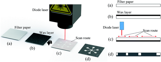
The fabrication procedure of the proposed paper-based microfluidics is shown in Fig. 1. The blank filter paper was evenly printed with a layer of evenly distributed wax (with a thickness around 50 μm) using a commercial wax printer (Fig. 1b), however, there are several other options to deposit a layer of wax, e.g. with screen-printing25 or even hand painting with crayon.20The filter paper covered with a wax layer was then flipped over, and a custom-made diode laser scan system was used for the scan of designed patterns on the back side (the side without wax) on the filter paper (shown in Fig. 1c). The wavelength of the diode laser is 445 nm with an output power of 1 W, the moving speed of the laser head is 100 mm s−1. The laser head could be programmed to move in a plane with the control of step motors. During the laser scanning process, the irradiated spot on the surface of paper has a significant rise of temperature, causing the wax material on the other side of the filter paper to melt down and penetrate through the whole thickness of the filter paper to form the hydrophobic barriers for paper-based microfluidics (shown in Fig. 1d).
The custom-made diode laser system used in this approach is shown in Fig. 2, the position of the diode laser head was controlled by two step motors moving in a plane. For the planning of the laser scan route, the pattern (region) requiring a laser scan was designed with AutoCAD 2018 (Autodesk, Inc.) and then transferred to Mastercam X9 (CNC Software, Inc.). With the help of the milling module, the route planning was automatically conducted, and the generated G-code was finally sent to a control panel for the control of step motors during the laser scan process.
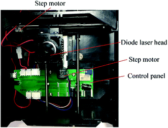 | ||
| Fig. 2 The custom-made diode laser ablation instrument for the fabrication of paper-based microfluidics. | ||
Results and discussion
A commercial wax printer was used to apply an evenly distributed layer (∼50 μm in thickness) of wax, and then applied to the diode laser ablation process with a laser power of around 1 W. Fig. 3 shows the front and back side of the filter paper covered with a wax layer after the laser scan. As shown in Fig. 3, the wax at the laser treated area penetrated through the whole thickness of the filter paper due to the thermal reflow caused by laser ablation. The wax pattern that penetrated throughout the whole thickness of filter paper formed the hydrophobic barriers (e.g. reservoirs and channels) for the paper-based microfluidics. For the paper and wax material used in this approach, a diode laser with a wavelength of 445 nm and a power of 1 W was found to be suitable to trigger the wax reflow without causing burning and evaporation of the paper and wax. However, the thickness of the wax layer, laser power, and scan speed need to be adjusted when using different papers to ensure the wax could penetrate through the whole thickness of the filter paper.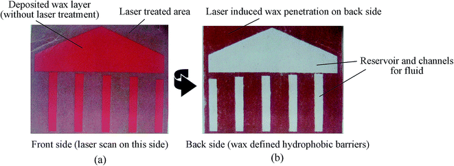 | ||
| Fig. 3 Front and back sides showing the laser-induced penetration of the paper-based microfluidic devices: (a) front side after diode laser scan; (b) back side after diode laser scan. | ||
The testing of the fabrication accuracy (resolution) for the proposed paper-based microfluidics fabrication technique was also conducted in this study. As shown in Fig. 4a, the minimum dimension of the wax barrier that could be achieved on the back side of the filter paper is 0.5 mm, and the minimum width of the effective wax barrier (the one that could completely block the fluid flow in cellulose fiber) is 1 mm. Fig. 4b shows a series of channels fabricated on the back side of the filter paper after laser ablation; the results show that the minimum width of the microchannel could be achieved with the proposed fabrication technique is 0.3 mm.
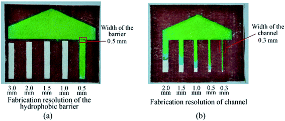 | ||
| Fig. 4 The testing of the hydrophobic wax barrier induced with laser ablation: (a) fabrication resolution test for the wax barrier; (b) fabrication resolution test for the microchannels. | ||
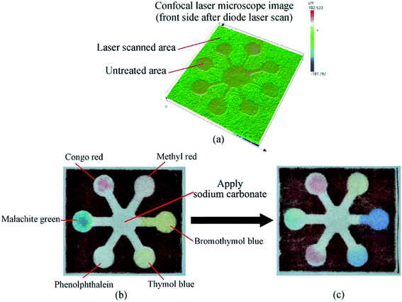
For the demonstration of the proposed fabrication technique for paper-based microfluidics, a universal pH test μPAD was fabricated as shown in Fig. 5. Fig. 5a shows a laser confocal microscope image for the front side of the filter paper after wax deposition and laser treatment, due to the reflow and penetration of the wax material during the laser treatment process, the laser treated area sunk around 10 μm after wax reflow and penetration. For the universal pH test μPAD shown in Fig. 5, various color changing compounds (Congo red, methyl red, malachite green, phenolphthalein, thymol blue, and bromothymol blue) were applied at various testing reservoirs and dried. Fig. 5b and c show the color changes of the testing reservoirs when applying one drop (∼20 μL) of sodium carbonate solution in DI water (0.94 mol L−1).
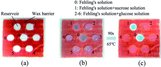
A simple μPAD for the detection of glucose was also fabricated for the demonstration of the proposed technology (shown in Fig. 6). The designed wax pattern was printed on the Whatman filter paper, and then the thermal reflow of wax was conducted using a diode laser with a power of 1 W and a moving speed of 100 mm s−1. Fehling's solution was sourced from Sigma-Aldrich (7758-97-7), the sucrose solution was prepared with a concentration of 10 mmol L−1, and the glucose solution was also prepared with a concentration of 10 mmol L−1. During the test, 30 μL of Fehling's solution was added to each of the reservoirs numbered from 0 to 6 using a pipette, after that, 30 μL of sucrose solution was added to reservoir 1, while 30 μL of glucose solution was added to the reservoirs numbered 2 to 6 (shown in Fig. 6b). Since Fehling's solution only reacts with reducing sugars (e.g. glucose), a chromogenic reaction between the aldehyde and the copper(II) ions occurred in reservoirs 2 to 6, resulting in a brick-red insoluble copper oxide (shown in Fig. 6c).
Conclusions
This study introduced a novel, simple and rapid method for the fabrication of paper-based microfluidic devices using diode laser induced wax penetration. Compared with previous approaches for forming hydrophobic wax barriers on paper material using a two-step approach (wax patterning and wax reflow), e.g. wax printing or wax stamping, the proposed technique only requires an ultra-low-cost diode laser that could achieve wax patterning and wax reflow simultaneously during the laser scan process. Other advantages of the proposed study include the low-cost and non-toxicity of the wax material, and also the easy adaption to various applications. However, the disadvantage of the proposed technique is the relatively low resolution compared with conventional photolithography fabrication methods. The proposed fabrication technique for paper-based microfluidics could have potential in broad applications for low-cost point-of-care testing and diagnostics, especially in developing countries.Conflicts of interest
There are no conflicts to declare.Acknowledgements
This work was supported by the National Natural Science Foundation of China (No. 51804014) and the Beijing Natural Science Foundation (2182055).References
- A. W. Martinez, et al., Patterned paper as a platform for inexpensive, low-volume, portable bioassays, Angew. Chem., 2007, 46(8), 1318–1320 CrossRef CAS PubMed.
- Y. Wang, et al., A novel label-free microfluidic paper-based immunosensor for highly sensitive electrochemical detection of carcinoembryonic antigen, Biosens. Bioelectron., 2016, 83, 319–326 CrossRef CAS PubMed.
- X. Yin, et al., Double signal amplification based on palladium nanoclusters and nucleic acid cycles on a μPAD for dual-model detection of microRNAs, J. Mater. Chem. B, 2018, 6(36), 5795–5801 RSC.
- S. Cho, et al., Smartphone-based, sensitive μPAD detection of urinary tract infection and gonorrhea, Biosens. Bioelectron., 2015, 74, 601–611 CrossRef CAS PubMed.
- B. M. Jayawardane, I. D. McKelvie and S. D. Kolev, Development of a gas-diffusion microfluidic paper-based analytical device (μPAD) for the determination of ammonia in wastewater samples, Anal. Chem., 2015, 87(9), 4621–4626 CrossRef CAS PubMed.
- M. Ariza-Avidad, A. Salinas-Castillo and L. Capitán-Vallvey, A 3D μPAD based on a multi-enzyme organic–inorganic hybrid nanoflower reactor, Biosens. Bioelectron., 2016, 77, 51–55 CrossRef CAS PubMed.
- E. Carrilho, A. W. Martinez and G. M. Whitesides, Understanding wax printing a simple micropatterning process for paper-based microfluidics, Anal. Chem., 2009, 81(16), 7091–7095 CrossRef CAS PubMed.
- L. Yu and Z. Z. Shi, Microfluidic paper-based analytical devices fabricated by low-cost photolithography and embossing of Parafilm®, Lab Chip, 2015, 15(7), 1642–1645 RSC.
- K. Yamada, et al., Paper-based inkjet-printed microfluidic analytical devices, Angew. Chem., 2015, 54(18), 5294–5310 CrossRef CAS PubMed.
- T. M. G. Cardoso, P. T. Garcia and W. K. T. Coltro, Colorimetric determination of nitrite in clinical, food and environmental samples using microfluidic devices stamped in paper platforms, Anal. Methods, 2015, 7(17), 7311–7317 RSC.
- Y. He, et al., 3D Printed Paper-Based Microfluidic Analytical Devices, Micromachines, 2016, 7(7), 108 CrossRef PubMed.
- B. Chumo, M. Muluneh and D. Issadore, Laser micromachined hybrid open/paper microfluidic chips, Biomicrofluidics, 2013, 7(6), 64109 CrossRef CAS PubMed.
- Y. Fan, et al., Milk carton with integrated paper-based microfluidics for milk quality rapid test, J. Food Saf., 2018, e12548 CrossRef.
- M. Liu, C. Zhang and F. Liu, Understanding wax screen-printing a novel patterning process for microfluidic cloth-based analytical devices, Anal. Chim. Acta, 2015, 891, 234–246 CrossRef CAS PubMed.
- Y. Yao and C. J. B. m. Zhang, A novel screen-printed microfluidic paper-based electrochemical device for detection of glucose and uric acid in urine, Biomed. Microdevices, 2016, 18(5), 92 CrossRef PubMed.
- F. Liu, C. J. S. Zhang and A. B. Chemical, A novel paper-based microfluidic enhanced chemiluminescence biosensor for facile, reliable and highly-sensitive gene detection of Listeria monocytogenes, Sens. Actuators, B, 2015, 209, 399–406 CrossRef CAS.
- M. Díaz-González, A. Baldi and C. Fernández-Sánchez, Compact sampling device based on wax microfluidics, Sens. Actuators, B, 2017, 251, 93–98 CrossRef.
- T. Songjaroen, et al., Novel, simple and low-cost alternative method for fabrication of paper-based microfluidics by wax dipping, Talanta, 2011, 85(5), 2587–2593 CrossRef CAS PubMed.
- Z. a. Li, et al., Fabrication of paper micro-devices with wax jetting, RSC Adv., 2016, 6(22), 17921–17928 RSC.
- Z. Zhong, Z. Wang and G. Huang, Investigation of wax and paper materials for the fabrication of paper-based microfluidic devices, Microsyst. Technol., 2012, 18(5), 649–659 CrossRef.
- S. Liu, et al., Fabrication of Cyclo-olefin polymer-based microfluidic devices using CO2 laser ablation, Mater. Res. Express, 2018, 5(9), 095305 CrossRef.
- J.-Y. Cheng, et al., Crack-free direct-writing on glass using a low-power UV laser in the manufacture of a microfluidic chip, J. Micromech. Microeng., 2005, 15(6), 1147 CrossRef CAS.
- N. Fakhri, M. Hosseini and O. Tavakoli, Aptamer-based colorimetric determination of Pb2+ using a paper-based microfluidic platform, Anal. Methods, 2018, 10(36), 4438–4444 RSC.
- P. Dilna, et al., Paper Based Microfluidic Device for the Detection of Total Protein in Blood, Mater. Today: Proc., 2018, 5(8), 16220–16225 CAS.
- W. Dungchai, O. Chailapakul and C. S. Henry, A low-cost, simple, and rapid fabrication method for paper-based microfluidics using wax screen-printing, Analyst, 2011, 136(1), 77–82 RSC.
| This journal is © The Royal Society of Chemistry 2019 |

