
 Open Access Article
 This Open Access Article is licensed under a Creative Commons Attribution-Non Commercial 3.0 Unported Licence
Construction of a graphene/polypyrrole composite electrode as an electrochemically controlled release system
Mo Zhu†
ab,
Ying Hao†b,
Xun Mab,
Lin Fengb,
Yuanxin Zhaib,
Yaping Ding a and
Guosheng Cheng*b
a and
Guosheng Cheng*b
aDepartment of Chemistry, Shanghai University, Shanghai 200444, P. R. China
bCAS Key Laboratory of Nano-Bio Interface, Suzhou Institute of Nano-Tech and Nano-Bionics, Chinese Academy of Sciences, Jiangsu 215123, P. R. China. E-mail: gscheng2006@sinano.ac.cn
First published on 23rd April 2019
Abstract
A new class of stimuli responsive drug delivery systems is emerging to establish new paradigms for enhancing therapeutic efficacy. To date, most electro-responsive systems rely on noble metal electrodes that likely cause the limitations for implantation applications. Herein, a graphene/polypyrrole composite electrode (GN–PPy–FL) was fabricated based on two-dimensional (2D) graphene (GN) film and conductive and biocompatible polypyrrole (PPy) nanoparticles loaded with a negative drug model of fluorescein sodium (FL) via chemical oxidation polymerization. The conductive composite electrode was utilized as a drug carrier to realize the electrically controlled release of the FL. The release rate from conductive nanoparticles can be controlled by the applied voltages. The study provides a multi-stimuli responsive drug release system, demonstrating the potential applications of the controlled release of various drugs, peptides or proteins.
Introduction
Stimuli-responsive material offers great advantages over traditional therapies by reducing toxic side effects and increasing drug efficacy. It can respond to local stimuli to enhance the accumulation of drugs in the pathological site, prolong the circulation time of drugs and achieve efficient delivery of drugs.1,2 Many efforts have been devoted to developing a variety of stimuli-responsive polymers for drug delivery systems (DDSs) to realize the controlled release of drugs.3 Controlled release of drugs from DDSs can be achieved by their response to the changes in environmental factors such as temperature,4 pH,5 light,6 enzymes,7 redox,8 or an electric/magnetic field.9,10 Among these systems, the electro-responsive system is emerging to present a controlled release profile that mimics physiological processes in electroactive tissues owing to its intriguing properties of the versatility on the design of electrical stimulation devices or DDSs,11 as well as the controllability through the tunable magnitude of voltage, frequency and pulse time. Besides, it has been reported that mild electrical stimulation facilitated the promotion of cell proliferation or differentiation,12 providing the potential of electro-responsive DDSs in tissue engineering.Electro-responsive systems have been established from nanoparticles,13 hydrogels14 or thin films15 based on conducting polymers, which possess unique electrical, optical mechanical and topological properties, providing sensitivity and response to electrical stimuli. These features, coupled with their excellent biocompatibility and facile functionalization with biomolecules, have empowered conducting polymers to fuel the developments of drug delivery devices, neural electrodes, and tissue engineering.16–18 Conducting polymers such as polyaniline (PANI), polypyrrole (PPy), polythiophene (PTh) and poly(3,4-ethylenedioxythiophene) (PEDOT) are of considerable interest for DDSs.19 As one of promising conducting polymers, PPy has been proved to be a biocompatible material for DDSs with the advantageous features of facile preparation, stability and favorable conductivity.20,21 For instance, conductive PPy microcups with tunable size has been developed for the release of anti-inflammatory drug, of which the release behavior can be controlled by precisely modulating the physical surface properties of PPy microcups.22 To increase the drug efficiency, PPy was commonly employed to fabricate composite materials with a combination of biocompatible or biodegradable polymers23,24 or hydrogels.25 Most of the reports have focused on the composite PPy film by coating on the surface of substrate through the electrodeposition that requires a stiff electrode, causing limitations for implantation applications. To address the limitations, PPy nanoparticles have been developed to form composite material via the chemical methods. In addition, the micro- and nano-structures of conductive nanoparticles can enhance the drug loading capacity.8,26
Graphene (GN), a two-dimensional (2D) nanosheet of sp2-hybridized carbon atoms with a packed honeycomb lattice structure, has been rapidly developed in chemistry, physics and biology. Given the well-known electrical conductivity, ultra-high surface area and good biocompatibility, graphene and its derivatives have attracted extensive interests in supercapacitors, bio-sensing/imaging, drug/gene delivery and tissue engineering.27,28 Because of the extremely large surface area, graphene can physically adsorb or chemically conjugate with small molecules, proteins or functional nanoparticles, serving as a carrier.29 Notably, graphene-based conductive platform has been reported to support cell growth and promote the differentiation of stem cell.30 Moreover, the incorporation of electro-responsive controlled release system for drugs, bioactive peptides or proteins provides biomimetic microenvironment to mediate cell behaviors.31 Thus, controlled release system based on conductive composite plays a crucial role in therapeutic treatments and tissue regeneration.32 Composite materials fabricated by graphene and polymers are promising candidates for drug delivery. However, some developed system realized the release through desorption of drugs from graphene triggered by pH/redox, probably limiting the control of drug dosing in real time.33,34 Drug release of electro-responsive graphene/polymer hydrogels systems mainly rely on the high voltages that might cause the damage to the biological system.35,36 Besides, the reported Graphene Oxide (GO)/PPy composite film required an extra stiff electrode as substrate for graphene and drugs additives.29
Considering the competitive conductivity and flexibility of 2D GN film, as well as the remarkable drug loading capacity of PPy nanoparticles, we here report on a novel fluorescein sodium (FL) loaded electro-responsive graphene/polypyrrole composite electrode (GN–PPy–FL). As shown in Fig. 1a, the negative charged FL was first incorporated in PPy by electrostatic interaction to form PPy–FL nanoparticles via the chemical oxidation polymerization using poly(vinyl alcohol) as the stabilizing agent and iron cations as the oxidizing agent. 2D GN film synthesized by chemical vapor deposition was used as an electrode substrate,37 which was interacted with PPy–FL nanoparticles via the π–π interactions between the benzene ring in graphene film and the aromatic group in PPy nanoparticles. Besides, the formed GN–PPy–FL can realize the electric-triggered release of drug through controlling the voltage applied on the electrode (Fig. 1b). The responsive FL release behaviors were investigated by changing local pH or voltages. Furthermore, cytotoxicity against neural stem cells was evaluated to verify the biocompatibility of GN–PPy–FL, indicating its potentials for controlled release of bioactive molecules in microchips for tissue engineering application.
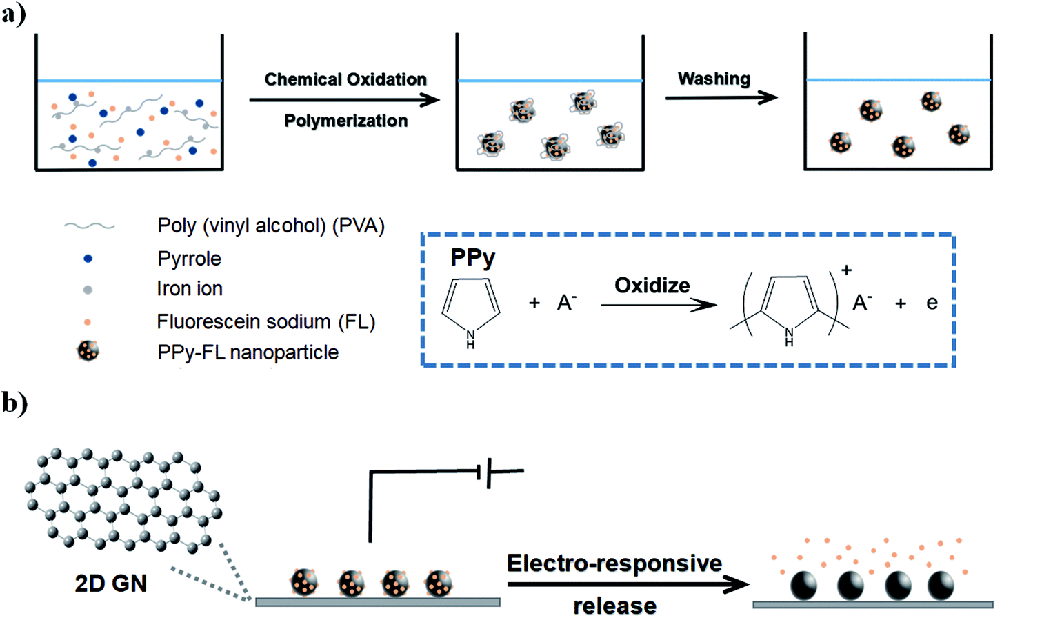 | ||
| Fig. 1 Schematic illustration of the PPy–FL nanoparticles formation (a), and electrochemically triggered release of FL from GN–PPy–FL (b). | ||
Experimental
Materials
Poly(vinyl alcohol) (PVA, 88% hydrolyzed, Mw 10 kDa), pyrrole and fluorescein sodium (FL) were purchased from Aladdin Co., Ltd., China. FeCl3·6H2O was provided from Sinopharm Chemical Reagent Co., Ltd., China. Solder Paste Inspection (SPI) conducting silver paste was purchased from Structure Probe, Inc., USA. 3410 glue was obtained from Dow Corning, Corp., USA. Pt counter was purchased from Tianjin Ida Technology Co., Ltd., China. Poly-L-ornithine solution and laminin solution were purchased from Sigma (USA). Calcein-AM and ethidium homodimer-1 (EthD-1) were purchased from Santa Cruz Biotechnology, Inc., USA and Abcam, Inc., USA, respectively.Synthesis of FL-loaded PPy nanoparticles
To prepare the PPy–FL nanoparticles, 0.5 g of PVA was dissolved in 20 mL deionized (DI) water and heated up to 105 °C. After cooling down to the room temperature, 15 mg of FL was added and the mixture was stirred at room temperature for 30 min. Afterwards, FeCl3·6H2O was added, the mixture was cooled to 5 °C. Then 69 μL of pyrrole monomer was added dropwise into the aqueous PVA/FeCl3/FL solution. The molar ratio of FeCl3 to pyrrole was 2![[thin space (1/6-em)]](https://www.rsc.org/images/entities/char_2009.gif) :1 according to the literature.38 After 24 h of polymerization at 5 °C, the resulting nanoparticles in black were rinsed by repeated washing with DI water. Excess PVA was removed by ultrafiltration filters. Then, dispersion of nanoparticles was placed in a dialysis bag (MWCO 14 kDa) against DI water to remove impurities and free FL. The dialysis medium was changed three times per day during the 3 days. PPy nanoparticles were synthesized by the similar protocol without the step of adding FL.
:1 according to the literature.38 After 24 h of polymerization at 5 °C, the resulting nanoparticles in black were rinsed by repeated washing with DI water. Excess PVA was removed by ultrafiltration filters. Then, dispersion of nanoparticles was placed in a dialysis bag (MWCO 14 kDa) against DI water to remove impurities and free FL. The dialysis medium was changed three times per day during the 3 days. PPy nanoparticles were synthesized by the similar protocol without the step of adding FL.
The morphologies of the PPy and PPy–FL nanoparticles were characterized by scanning electron microscopy (SEM) (Quanta 400 FEG, FEI, USA). The sizes and size distributions of the nanoparticles were measured using dynamic light scattering (DLS) (Malvern, Zetasizer Nano ZS, UK). The UV-vis spectra of the FL solution, PPy and PPy–FL nanoparticles were obtained by using a UV/vis Spectrometer (PerkinElmer Lambda 25, Canada) with a quartz cuvette of 1 cm optical path length. The fluorescence of nanoparticles was analyzed using an inverted fluorescence microscopy (Eclipse Ti-U, Nikon, Japan).
Fabrication of the 2D graphene substrate
2D graphene substrates were fabricated via chemical vapor deposition.39 Typically, a thin copper foil substrate was heated up to 950 °C and annealed for 10 min under H2 and Ar atmospheres, followed by exposing to H2, Ar and CH4 for 3 min at a usual atmospheric pressure. The furnace was cooled down to the room temperature under Ar atmosphere. After growth, copper substrate was removed by etching in an aqueous solution of iron nitrate to yield 2D GN film, which was rinsed sequentially with diluted HNO3 solutions and DI water. Lastly, 2D GN film was transferred to tissue-culture polystyrene substrate (TCPs), followed by dried at room temperature for at least three days. Afterwards, it was soaked into DI water to remove the residual of etching agents and then was dried at room temperature for another 3 days.Fabrication of GN–PPy–FL composite electrode
The PPy or PPy–FL nanoparticles were dispersed in DI water and sonicated for 30 min. The prepared 2D GN substrate was immersed in this dispersion for 24 h to obtain composite electrode. Then it was washed with DI water for three times, and soaked in DI water for 4 h to fully remove unabsorbed PPy–FL nanoparticles. Subsequently, the substrate was dried at room temperature for 24 h to obtain a final GN–PPy–FL. To set up the electrode device, the Cu wire was connected to the edge of the composite electrode with conducting silver paste, while 3410 glue was coated on the surface of the silver paste to fix it.An electrochemical workstation (CHI 660E, Chinstruments, Shanghai) was used as a power source to test the cyclic voltammograms (CV) and electrochemical impedance performances (EIS) of the 2D GN film and composite electrode. 0.1 M phosphate buffer saline (PBS) was utilized as the electrolyte. The CV was tested with a potential range from −0.4 to 0.8 V at a scan rate of 100 mV s−1. The EIS were conducted at the open circuit potential in a frequency range from 1 Hz to 100 kHz, and the impedance–potential curves were also recorded with the potential range of −0.4 V to 0.8 V. The chemical compositions were examined by Raman spectroscopy (LABRAM HR800, HORIBA, France). The charge storage capacity was calculated based on the surface area contained inside the CV curves and determined by using OriginLab software.
pH-responsive FL release
To investigate the release of FL from the composite electrode, GN–PPy–FL were respectively immersed in 2 mL of phosphate buffer solution (PB) (0.2 M) at pH 5.0, 7.4 and 9.0 for 24 h under room temperature in dark. The release concentration of FL in PB was calculated based on the standard addition method.40 Briefly, after 24 h of release, 150 μL of each PB media was taken out and placed in each of 4 wells in a 96-well plate, and then 0, 10, 20, and 30 μL of FL standard stock solution (10 μg mL−1) were added in each well successively. The total volume of each well was set to 180 μL by adding PB. The fluorescence intensity was measured by a microplate reader (Victor™×4, PerkinElmer, Singapore) to plot the fluorescence intensity–concentration curve. The X-intercept of the regression line indicated the release concentration of FL. The measurements were performed in triplicate. All data were expressed as mean ± standard deviations (SD).Electric-responsive FL release
To evaluate the electric triggered FL release behavior, a two-electrode electrochemical cell was set up in a homemade device, with the platinum (Pt) electrode as the counter electrode and the composite electrode as the working electrode. 10 mL of PBS (pH = 7.4) (0.01 M) was used as the supporting electrolyte. Different voltages were separately applied for electrical stimulation. At a predetermined time, the solution was collected and placed in a 96-well plate in dark. Then, fresh PBS solution was replenished to the electrolyte to maintain the total volume. Thereafter, the 96-well plate was placed in a microplate reader for fluorescence intensity measurement. Five independent measurements were averaged for each set. All data were expressed as mean ± SD.Cell viability assay
For cell experiment, 2D GN film and GN–PPy–FL were thoroughly sterilized by 75% ethanol and then were transferred into a 96-well plate. Sterilized PBS buffer was added in each well for 15 minutes to wash for three times. Subsequently, 2D GN film and GN–PPy–FL, as well as the control wells (TCPs) were successively coated by poly-L-ornithine solution overnight at 4 °C and laminin solution in PBS for 4 h at 37 °C. After sterilized PBS washing for three times, neural progenitor cells (NPCs) were seeded at a density of 104 cells per well on different substrates of TCPs, 2D GN film and GN–PPy–FL, respectively. After 5 days of culture, cell viability assay was tested by staining with Calcein-AM for live cells and EthD-1 for dead cells. The labelled cells were imaged by inverted fluorescence microscopy (Eclipse Ti-U, Nikon, Japan). Analysis was performed in triplicate for each condition. The cytotoxicity assay data were presented as the mean ± SD.Statistical analysis
One-way analysis of variance (ANOVA) was performed to compare the data set. A P value less than 0.05 was considered significant.Results and discussion
Synthesis and characterizations of PPy–FL nanoparticles
The PPy or PPy–FL nanoparticles were synthesized by chemical oxidation polymerization, using poly(vinyl alcohol) as a stabilizing agent and FeCl3 as an oxidizing agent.41 Due to the large surface area as reported,42 poly(vinyl alcohol) agent can increase the stability and dispersity, which is beneficial to the electrical conductivity of stimuli-responsive PPy nanoparticles. A drug model of FL was mixed with the pyrrole monomer during the synthesis of PPy. The negative charged FL was incorporated into the PPy nanoparticles to counterbalance the positive charge through the electrostatic interaction. The oxidation of PPy provides a facile mechanism for the uptake of a wide range of molecules.43,44 Based on this synthesis, other molecules including drugs, peptides and bioactive factors can be loaded into polymer by physical embedding associated with the mechanism of oxidative polymerization.The morphologies of formed PPy or PPy–FL nanoparticles were visualized by SEM, exhibiting a spherical shape with diameter around 100 nm (Fig. 2a). Besides, DLS was employed to measure the averaged diameter and size distribution of the nanoparticles, showing the size around 133 nm and 167 nm for PPy and PPy–FL, respectively. The results reflected the good stability and uniformity (Fig. 2b). Furthermore, the UV-vis spectra of PPy–FL nanoparticles in Fig. 2c showed a clear UV absorption peak at 495 nm, which was attributed to the presence of FL. The fluorescence image visually provided an evidence that drug model FL has been successfully loaded into PPy nanoparticles and the FL was stable without degradation during the oxidation (Fig. 2d). The red shift of FL absorption peak can be attributed to the increased conjugate ability between FL molecules and PPy.
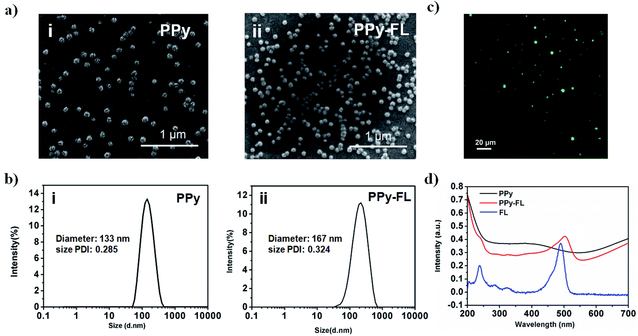 | ||
| Fig. 2 SEM micrographs (a) and dynamic light scattering size distributions (b) of PPy nanoparticles (i) and PPy–FL nanoparticles (ii). The fluorescence image of PPy–FL nanoparticles (c); and the UV extinction spectra (d) of FL solution, PPy and PPy–FL nanoparticles. | ||
Fabrication and characterizations of composite electrode
The conductive composite electrode was prepared via a combination of 2D GN film and PPy–FL nanoparticles. 2D GN film was synthesized by chemical vapor deposition. Next, PPy–FL nanoparticles were composited on 2D GN surface by π–π stacking interactions between PPy and graphene structures. According to Fig. 3, the Raman spectra of the composite electrode with a laser excitation at 532 nm exhibited the characteristic D-band (at 1350 cm−1), G-band (at 1582 cm−1), and 2D-band (at 2700 cm−1) of graphene (Fig. 3). Typically, high quality sections of low layer graphene were observed for the symmetry of 2D-band and the intensity ratio of the 2D-band and G-band (I2D/IG). Due to the presence of instinct vibrational modes at D-band (at 1340 cm−1) and G-band (at 1590 cm−1) for PPy, the ratio of the D-band and G-band (ID/IG) of GN–PPy–FL increased compared with graphene.45 Besides, the Raman spectra of the composite electrode showed the characteristic peaks of PPy (1170 cm−1 attributing to antisymmetrical C–H in-plane bending, 1420 cm−1 attributing to antisymmetrical C–N stretching, 1507 cm−1 attributing to skeletal band, and 1624 cm−1 attributing to the quinoid form band of C![[double bond, length as m-dash]](https://www.rsc.org/images/entities/char_e001.gif) C),46 indicating the successful combination of 2D GN film and PPy–FL nanoparticles. Also, these spectral features demonstrated that most PPy chains were still at intermediary oxidation levels after the incorporation with graphene film,47 implying the maintenance of electrochemical activity of the composite electrode.
C),46 indicating the successful combination of 2D GN film and PPy–FL nanoparticles. Also, these spectral features demonstrated that most PPy chains were still at intermediary oxidation levels after the incorporation with graphene film,47 implying the maintenance of electrochemical activity of the composite electrode.
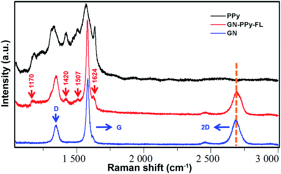 | ||
| Fig. 3 Micro-Raman spectra of PPy, 2D graphene film (GN) and GN–PPy–FL. | ||
The composite electrode with customized size was used as the working electrode to connect with the Cu wire, while 3410 glue was applied on the surface to prevent silver paste from electrolyte (Fig. 4a). The electrochemical performance of GN–PPy–FL as the electrode material was tested by cyclic voltammetry (CV) and electrochemical impedance spectroscopy (EIS) in a three-electrode system. The electro-activity was verified from CV curves by using the composite electrode as the working electrode. The CV curves of GN–PPy–FL in phosphate buffered saline (PBS) showed a clear redox peak in a potential range between −0.4 and 0.8 V (vs. saturated calomel electrode (SCE)) (Fig. 4b). In terms of the surface area, the charge storage capacity values were calculated as 28.86 ± 0.75 and 52.45 ± 1.30 mC cm−2 for 2D GN film and GN–PPy–FL, respectively. The charge storage capacity of composite electrode was higher than that of some reported conductive hydrogel or conducting polymer based drug delivery systems.22,48,49 The composite electrode presented highly capacitive nature with good ion response. The results further indicated that the composite electrode possesses a larger capacitance and a stronger charge injection ability compared with 2D GN film due to the presence of conductive polymer particles. Meanwhile, according to the electrochemical impedance spectroscopies (EIS) results presented in Fig. 4c and d, the difference in impedance values increased with the increasing frequency, and impedance values and the resistance of GN–PPy–FL were significantly lower than those of 2D GN film, indicating that the conductive polymer nanoparticles significantly increase the charge storage capacity and decrease the impedance of the graphene electrode, suggesting the potentials of GN–PPy–FL as an ideal electrode material.
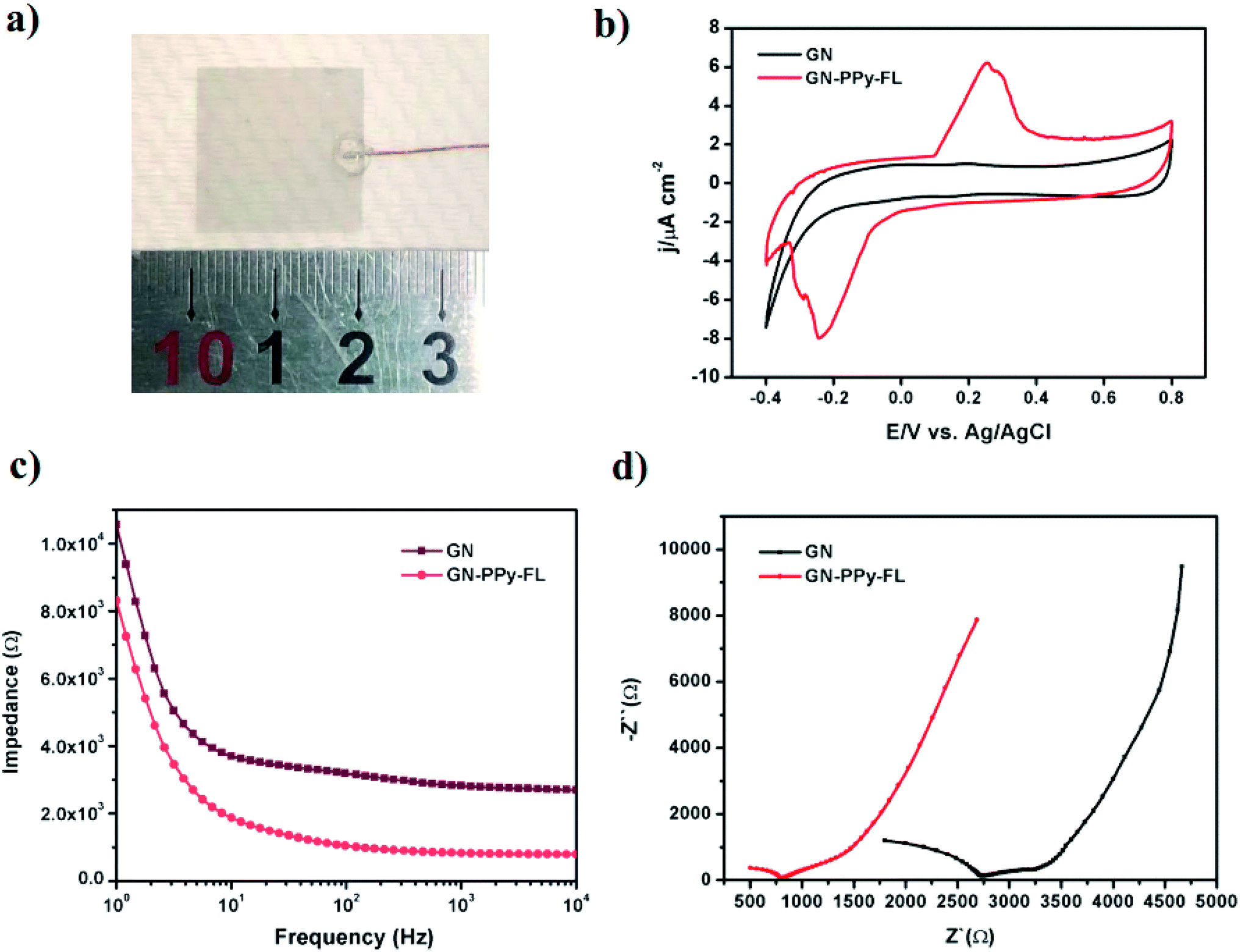 | ||
| Fig. 4 Digital photo (a) of GN–PPy–FL; cyclic voltammetry curves (b); impedance spectrum over a frequency range of 1–104 Hz (c) and Nyquist plots of impedance spectrum (d) of GN and GN–PPy–FL. | ||
Responsive release behaviors from composite electrode
Considering the negativity of FL, we first tested the release of FL from GN–PPy–FL at different pH of 5.0, 7.4 and 9.0 by standard addition method. Fig. 5 showed the larger released amount of FL with the increasing pH after 24 h, significant difference (P < 0.05) was observed among three pH values, reflecting the pH responsive behavior of FL from GN–PPy–FL. However, for the potential use as a microchip, the local pH of specific tissue usually keeps stable. Therefore, the response to other triggers such as electrical trigger are required. To assess an electrical responsive drug release behavior, a two-electrode electrochemical cell was designed by using the composite electrode as the working electrode and the Pt electrode as the counter electrode. PBS was used as electrolyte to mimic physiological conditions in vivo. Different voltages of −1.5 V, 0 V and +1.0 V were used to measure the FL release behaviors as shown in Fig. 6. Much more FL was released when a constant stimulation of −1.5 V was applied to composite electrode, compared to the controls of 0 V and +1.0 V, indicating the electrochemical release of FL.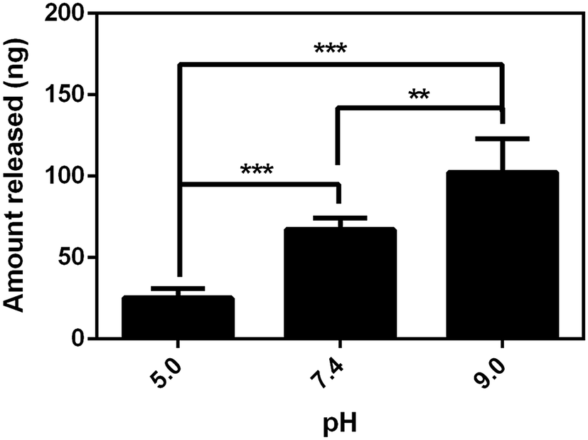 | ||
| Fig. 5 FL release from composite electrode at three different pH values. **P value < 0.01 and ***P value < 0.001, n = 6. | ||
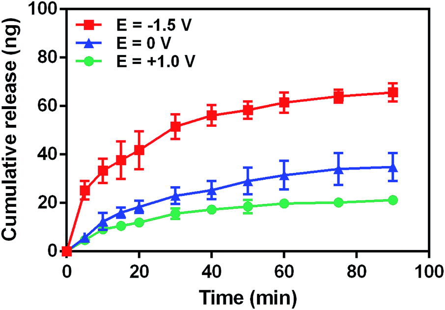 | ||
| Fig. 6 Cumulative FL release profile from composite electrode under various voltages of −1.5 V, 0 V and +1.0 V. | ||
Next, we sought to explore the mechanism of the pH responsive and electro-responsive release behaviors of drug model. It has been reported that higher pH caused more deprotonation in terms of the reported protonation pKa of PPy,40 lowering its overall positive charge, thus decreasing the electrostatic interactions between PPy and negatively charged drug to release the FL. Many reports have revealed that water electrolysis can lead to local pH value change.31,50,51 The window for water electrolysis is −0.6 V to 0.8 V vs. Ag/AgCl. The negative potential may result in the generation of OH− ions on the GN–PPy–FL composite electrode surface, increasing pH on the surface of the working electrode to favor the release of negative drug from the nanoparticles. On contrary, when a positive voltage was applied, water electrolysis lead to locally decreased pH around the GN–PPy–FL composite electrode to impede the drug release. Besides, the electro-responsive release of FL can also be ascribed to the redox properties of PPy that affect electrostatic interaction between PPy and FL. Applying electrical stimulation can cause the conformational change of conducting polymers.25,52 To maintain the charge neutrality, it requires mass transport between the PPy and electrolyte.53 Counterions can enter/exit the conducting polymer, causing the expansion/contraction of polymer when applying the voltage. PPy nanoparticles on the working electrode were reduced when applying the negative potential. Electrons can be injected into the polymer backbone to expel the negatively charged drug FL to overall charge neutrality, resulting in the release of FL.
Cell viability
Cytotoxicity is one of critical issue for the application of a biological electrode material. It is noted that electrical stimulation has a significant effect on the release of bioactive factors on stem cell behaviors.54 Meanwhile, electrical stimulation mediates the stem cell adhesion, migration or differentiation behaviors.12 For potential use in nerve tissue engineering, NPCs was selected to verify the biocompatibility of composite electrode in vitro. NPCs cultured on the substrates after 5 days were stained with Calcein-AM and EthD-1, respectively. The fluorescence microscopy images as displayed in Fig. 7a revealed that the most NPCs treated with GN–PPy–FL and control groups of TCPs and 2D GN film were highly viable with the minimal dead cells. The cell viability of NPCs in each condition were quantified as higher than 90% (Fig. 7b), presenting the biocompatibility of GN–PPy–FL. The result provides a promise of the electro-controlled release of bioactive proteins and the effects of electrical stimulation on nerve cells for nerve tissue engineering.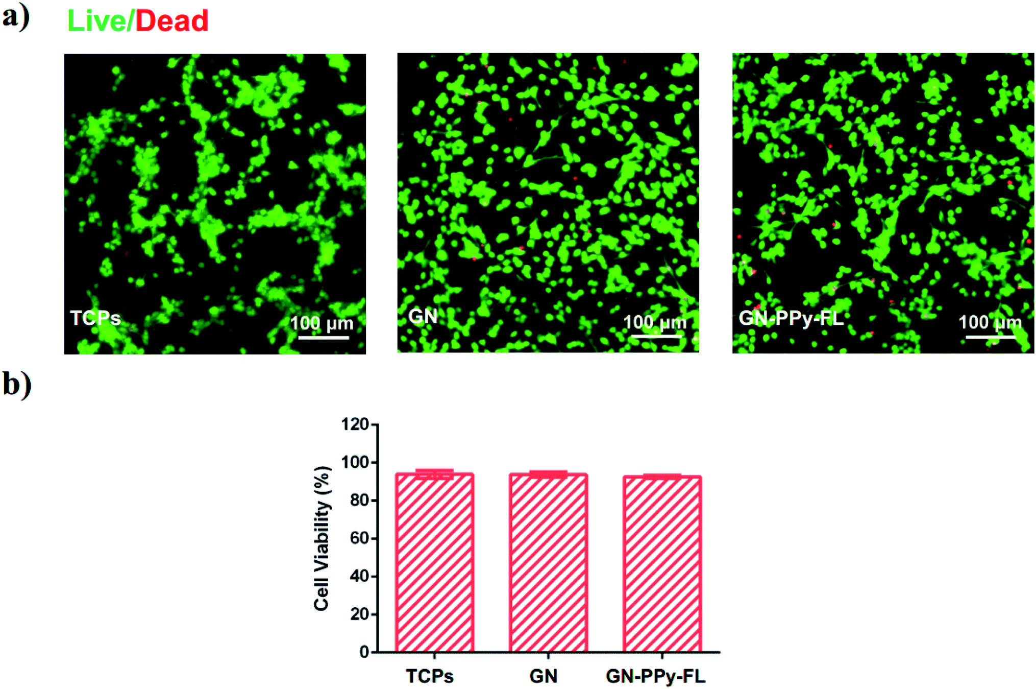 | ||
| Fig. 7 Representative images of fluorescently stained NPCs on TCPs, GN, GN–PPy–FL after 5 days of culture, live and dead cells were stained Calcein AM (green) and ethidium homodimer-1 (red), respectively (a), and quantification of cell viability based on live/dead assay (b). Scale bar: 100 μm. | ||
Conclusions
In conclusion, we have successfully developed a conductive composite electrode GN–PPy–FL through the interactions between 2D GN film and FL loaded PPy nanoparticles, which were prepared via chemical vapor deposition and chemical oxidation polymerization, respectively. This composite electrode exhibited favorable conductivity with a larger capacitance and a stronger charge injection ability, which can be utilized as a drug carrier to realize the electro-responsive controlled release. The release rate from conductive PPy–FL nanoparticles can be controlled by voltages or pH changes. Meanwhile, local pH changes and reduction on the electrode surface have impact on the electro-responsive release behavior of FL. Furthermore, stem cells NPCs can grow on GN–PPy–FL composite electrode and keep high viability, excellent biocompatibility. Overall, this conductive GN–PPy–FL composite electrode provides a perspective to achieve the electro-responsive release of drugs, peptides, proteins in nerve regeneration medicine for biomedical applications.Conflicts of interest
There are no conflicts to declare.Acknowledgements
The authors thank the Key Research and Development Program of Jiangsu Province (BE2017665), National Key Basic Research Program of China (973 Program grant no. 2014CB965003) and National Natural Science Foundation of China (31700831).References
- V. P. Torchilin, Nat. Rev. Drug Discovery, 2014, 13, 813–827 CrossRef CAS PubMed.
- S. Mura, J. Nicolas and P. Couvreur, Nat. Mater., 2013, 12, 991–1003 CrossRef CAS PubMed.
- S. Majumdar, G. Krishnatreya, N. Gogoi, D. Thakur and D. Chowdhury, ACS Appl. Mater. Interfaces, 2016, 8, 34179–34184 CrossRef CAS PubMed.
- Z. Jin, K. Wu, J. Hou, K. Yu, Y. Shen and S. Guo, Biomaterials, 2018, 153, 49–58 CrossRef CAS PubMed.
- M. M. Wan, J. Y. Yang, Y. Qiu, Y. Zhou, C. X. Guan, Q. Hou, W. G. Lin and J. H. Zhu, ACS Appl. Mater. Interfaces, 2012, 4, 4113–4122 CrossRef CAS PubMed.
- T. Zhao, L. Chen, Q. Li and X. Li, J. Mater. Chem. B, 2018, 7112–7121 RSC.
- P. D. Thornton and A. Heise, J. Am. Chem. Soc., 2010, 132, 2024–2028 CrossRef CAS PubMed.
- L. Yu, Y. Chen, H. Lin, W. Du, H. Chen and J. Shi, Biomaterials, 2018, 161, 292–305 CrossRef CAS PubMed.
- J. G. Hardy, M. N. Amend, S. Geissler, V. M. Lynch and C. E. Schmidt, J. Mater. Chem. B, 2015, 3, 5005–5009 RSC.
- Y. Gao, M.-W. Chang, Z. Ahmad and J.-S. Li, RSC Adv., 2016, 6, 88157–88167 RSC.
- J. J. T. Santini, A. C. Richards, R. Scheidt, M. J. Cima and R. Langer, Angew. Chem., Int. Ed., 2000, 39, 2396–2407 CrossRef CAS PubMed.
- K. F. Lei, I. C. Lee, Y. C. Liu and Y. C. Wu, Langmuir, 2014, 30, 14241–14249 CrossRef CAS PubMed.
- A. Manna, S. Pramanik, A. Tripathy, A. Moradi, Z. Radzi, B. Pingguan-Murphy, N. Hasnan and N. A. Abu Osman, RSC Adv., 2016, 6, 102853–102868 RSC.
- N. Mac Kenna, P. Calvert, A. Morrin, G. G. Wallace and S. E. Moulton, J. Mater. Chem. B, 2015, 3, 2530–2537 RSC.
- Z. J. Du, G.-Q. Bi and X. T. Cui, Adv. Funct. Mater., 2017, 28, 1703988 CrossRef PubMed.
- G. Malliaras and M. R. Abidian, Adv. Mater., 2015, 27, 7492 CrossRef CAS PubMed.
- D. Samanta, N. Hosseini-Nassab, A. D. McCarty and R. N. Zare, Nanoscale, 2018, 10, 9773–9779 RSC.
- S. Park, G. Yang, N. Madduri, M. R. Abidian and S. Majd, Adv. Mater., 2014, 26, 2782–2787 CrossRef CAS PubMed.
- Y. Zhao, A. C. Tavares and M. A. Gauthier, J. Mater. Chem. B, 2016, 4, 3019–3030 RSC.
- X. Luo and X. T. Cui, Electrochem. Commun., 2009, 11, 1956–1959 CrossRef CAS PubMed.
- J. G. Hardy, D. S. Hernandez, D. M. Cummings, F. A. Edwards, J. B. Shear and C. E. Schmidt, J. Mater. Chem. B, 2015, 3, 5001–5004 RSC.
- M. Antensteiner, M. Khorrami, F. Fallahianbijan, A. Borhan and M. R. Abidian, Adv. Mater., 2017, 29, 1702576 CrossRef PubMed.
- M. R. Abidian and D. C. Martin, Adv. Funct. Mater., 2009, 19, 573–585 CrossRef CAS.
- C. Vallejo Giraldo, A. Kelly and M. J. P. Biggs, Drug Discovery Today, 2014, 19, 88–94 CrossRef CAS PubMed.
- J. Ge, E. Neofytou, T. J. Cahill, R. E. Beygui and R. N. Zare, ACS Nano, 2012, 6, 227–233 CrossRef CAS.
- D. Park, Y. Cho, S.-H. Goh and Y. Choi, Chem. Commun., 2014, 50, 15014–15017 RSC.
- Z. Liu, J. T. Robinson, S. M. Tabakman, K. Yang and H. Dai, Mater. Today, 2011, 14, 316–323 CrossRef CAS.
- S. Pattnaik, K. Swain and Z. Lin, J. Mater. Chem. B, 2016, 4, 7813–7831 RSC.
- C. L. Weaver, J. M. LaRosa, X. Luo and X. T. Cui, ACS Nano, 2014, 8, 1834–1843 CrossRef CAS PubMed.
- N. Li, Q. Zhang, S. Gao, Q. Song, R. Huang, L. Wang, L. Liu, J. Dai, M. Tang and G. Cheng, Sci. Rep., 2013, 3, 1604 CrossRef PubMed.
- Q. Yao, J. Jing, Q. Zeng, T. L. Lu, Y. Liu, X. Zheng and Q. Chen, ACS Appl. Mater. Interfaces, 2017, 9, 39962–39970 CrossRef CAS PubMed.
- L. Wu, J. Wang, N. Gao, J. Ren, A. Zhao and X. Qu, Nano Res., 2015, 8, 2400–2414 CrossRef CAS.
- R. Justin and B. Chen, J. Mater. Chem. B, 2014, 2, 3759–3770 RSC.
- H. Bao, Y. Pan, Y. Ping, N. G. Sahoo, T. Wu, L. Li, J. Li and L. H. Gan, Small, 2011, 7, 1569–1578 CrossRef CAS PubMed.
- A. Servant, V. Leon, D. Jasim, L. Methven, P. Limousin, E. V. Fernandez-Pacheco, M. Prato and K. Kostarelos, Adv. Healthcare Mater., 2014, 3, 1334–1343 CrossRef CAS PubMed.
- H.-W. Liu, S.-H. Hu, Y.-W. Chen and S.-Y. Chen, J. Mater. Chem., 2012, 22, 17311–17320 RSC.
- D. Akinwande, N. Petrone and J. Hone, Nat. Commun., 2014, 5, 5678 CrossRef CAS PubMed.
- Y. Zhou, P. Wang, M. Hu and X. Tian, Electrochim. Acta, 2017, 249, 290–300 CrossRef CAS.
- X. Li, W. Cai, J. An, S. Kim, J. Nah, D. Yang, R. Piner, A. Velamakanni, I. Jung, E. Tutuc, S. K. Banerjee, L. Colombo and R. S. Ruoff, Science, 2009, 324, 1312–1314 CrossRef CAS PubMed.
- D. Samanta, J. L. Meiser and R. N. Zare, Nanoscale, 2015, 7, 9497–9504 RSC.
- J.-Y. Hong, H. Yoon and J. Jang, Small, 2010, 6, 679–686 CrossRef CAS PubMed.
- K. Yang, H. Xu, L. Cheng, C. Sun, J. Wang and Z. Liu, Adv. Mater., 2012, 24, 5586–5592 CrossRef CAS PubMed.
- G. G. Wallace and L. A. P. Kane-Maguire, Adv. Mater., 2002, 14, 953–960 CrossRef CAS.
- B. C. Thompson, S. E. Moulton, J. Ding, R. Richardson, A. Cameron, S. O'Leary, G. G. Wallace and G. M. Clark, J. Controlled Release, 2006, 116, 285–294 CrossRef CAS PubMed.
- T. T. Nguyen and N. H. Duong, J. Nanomater., 2016, 2016, 1–6 Search PubMed.
- S. Demoustier-Champagne and P.-Y. Stavaux, Chem. Mater., 1999, 11, 829–834 CrossRef CAS.
- X. Gao, W. Luo, C. Zhong, D. Wexler, S.-L. Chou, H.-K. Liu, Z. Shi, G. Chen, K. Ozawa and J.-Z. Wang, Sci. Rep., 2014, 4, 6095 CrossRef CAS PubMed.
- J. A. Chikar, J. L. Hendricks, S. M. Richardson-Burns, Y. Raphael, B. E. Pfingst and D. C. Martin, Biomaterials, 2012, 33, 1982–1990 CrossRef CAS PubMed.
- K. Krukiewicz and J. K. Zak, J. Mater. Sci., 2014, 49, 5738–5745 CrossRef CAS.
- F. Teodorescu, L. Rolland, V. Ramarao, A. Abderrahmani, D. Mandler, R. Boukherroub and S. Szunerits, Chem. Commun., 2015, 51, 14167–14170 RSC.
- D. Samanta, R. Mehrotra, K. Margulis and R. N. Zare, Nanoscale, 2017, 9, 16429–16436 RSC.
- M. R. Abidian, D. H. Kim and D. C. Martin, Adv. Mater., 2006, 18, 405–409 CrossRef CAS PubMed.
- E. Smela, Adv. Mater., 2003, 15, 481–494 CrossRef CAS.
- J. Jin, Z. Huang, G. Yin, A. Yang and S. Tang, Electrochim. Acta, 2015, 185, 172–177 CrossRef CAS.
Footnote |
| † These authors contributed equally to this work. |
| This journal is © The Royal Society of Chemistry 2019 |