 Open Access Article
The selectivity of poly(2-vinylpyridine-block-methyl methacrylate) copolymer films: an AFM study
Sana Rahima,
Adnan Murad Bhayoa,
Ghayas Uddin Siddiquia,
Aneela Maalikb,
Najma Memon c,
Muhammad Raza Shah
 a and
Muhammad Imran Malik
 *a
*a
aHEJ Research Institute of Chemistry, International Centre for Chemical and Biological Sciences (ICCBS), University of Karachi, Karachi 75270, Pakistan. E-mail: mimran.malik@iccs.edu
bDepartment of Chemistry, COMSATS University Islamabad Campus, Islamabad 45550, Pakistan
cNational Centre of Excellence in Analytical Chemistry, University of Sindh, Jamshoro, Sindh, Pakistan
First published on 28th May 2019
Abstract
In this study, the surface morphologies of poly(2-vinyl pyridine-block-methyl methacrylate), P(2VP-MMA), copolymer films were analyzed by atomic force microscopy. P(2VP-MMA) samples varying in total molar mass and individual block length were evaluated for variations in the surface morphologies of films cast from toluene on Si wafers. The incorporation of AuNPs into the polymer domain significantly influenced the surface morphology of the films. Variations in the surface morphology as a function of the polarity of the casting solvent were also examined. In this context toluene (a non-polar solvent), chloroform (of intermediate polarity) and ethyl acetate (a polar solvent) were employed as casting solvents. Toluene is a good solvent for PMMA compared to P2VP, chloroform has no preferential solvation, while ethyl acetate is a good solvent for P2VP compared to PMMA. The morphology of the films cast on substrates of distinctly different polarities, such as mica, Si wafers, and HOPG, were studied to appraise their selectivity. Finally, a detailed study of the effects of thermal annealing on the surface morphologies of P(2VP-MMA) and P(2VP-MMA)-AuNPs was conducted.
1. Introduction
Block copolymer (BCP) films offer a variety of self-organized patterned morphologies of molecular dimensions in a highly effective manner owing to differences between the compatibility and thermodynamic properties of the connected blocks. This high level of control over the nanostructure morphologies is required while working towards the miniaturization of electronic and optical devices.1–8 The microdomains can form spherical,9 lamellar,10 cylindrical,11 gyroid,7 or more complex shapes12,13 with a regular periodic order having typical repeat distances in a range of 10–100 nm, depending upon the length, connectivity, and mutual interactions of the different blocks. Various factors that contribute to variations in the surface morphology of films of BCPs include the molecular weight and composition of the BCPs, film thickness, annealing temperature, casting solvent, interfacial interactions, substrate pattern, solvent evaporation, and electric field.14–16As-prepared films of BCPs exhibit laterally different but highly ordered distributions of different polymeric components with microdomain sizes and characteristic distances at the nanoscale.17,18 These films have been used as self-organized templates for the synthesis of various inorganic materials, such as nanoparticles, nanoclusters, nanotubes, nanowires etc. The surface structure and morphology of BCP films depend upon the minimization of surface and interfacial energies.17 Different surface morphologies tend to be produced during film formation because of differences in interfacial energy between the blocks of the copolymer and the surface of the substrate in order to minimize the free energy.19 The mesoscale structure of BCPs in the bulk is determined by molecular parameters such as chain length, volume fractions of the components, degree of incompatibility, and temperature. However, there may be some additional driving forces that affect the structures of the films.20 Typically, polymeric components with the lowest surface energy will accumulate at the surface and the component with the lowest interfacial energy will be attracted to the supporting substrate.21 Furthermore, confinement of the material to a film thickness that is a non-integer multiple of the “natural” bulk repetition length can cause the film structures to deviate from the corresponding bulk material. Consequently, phase behavior in films of block copolymers is complex and exhibits a larger variety of structures compared to the bulk.22 Several approaches have been employed to manipulate the self-organization of BCPs, among which thermal annealing is one of the most advanced approaches for modifying the polymer structure at the nanoscale. Generally, post-deposition of the polymer onto the substrate leads to disordered structures. The polymers become mobile and structurally transform above the glass transition temperature (Tg). Thermally induced molecular motion reorganizes the amorphous portion into a more perfect crystalline form compared to bulk melting that destroys existing crystalline regions. Therefore, maximum crystallinity can only be achieved below the melting temperature (Tm).23–26
Block copolymers composed of poly(2-vinylpyridine) (P2VP) segments, containing pyridine moieties as side chains, have been used for many industrial applications. A typical example is utilization of P2VP block copolymers as templates for metal complexes to prepare nanoparticles (NPs).27–31 The NPs-P2VP based nanocomposite assemblies improve the functionality of electronic, photonic, and chemical devices due to the presence of the nitrogen atoms of the pyridine ring with an unshared electron pair that induces pH sensitivity.23 In addition, magnetic, photonic, chemical, and electrical properties of nanomaterials are very different from those of their bulk materials. Consequently, there have been several studies focusing on the incorporation of nanoparticles within the block copolymer microdomains.32–36 P(2VP-MMA) BCPs have been employed in a novel methodology for the preparation of nanostructured magnetic thermoset materials without metals.37 The study focused on the nanostructuration of poly(ionic liquid) BCPs and their subsequent magnetic thermosets. The degree of quaternization of the pyridine block plays the major role in the structuration and magnetism.
In this study, the selectivity of the morphology of BCP films with regard to total molar mass, the molar mass of individual blocks, the chemical composition of the parent materials, and the nature of casting solvent as well as the substrate is investigated. Poly(2-vinylpyridine)-block-poly(methyl methacrylate), P(2VP-MMA), is selected owing to the excellent stabilization behavior of P2VP for nanoparticles (NPs) and the large difference in the surface energies of both blocks. The conditions for achieving different patterns are optimized. These selectivity studies will help in tracking down a targeted morphology for any intended application. Atomic force microscopy (AFM), being a non-destructive imaging technique, is employed for the structural and morphological analysis of the films and gold nanoparticles incorporated into P(2VP-MMA). A meticulous study of the effect of the casting solvent, molecular weight, chemical composition, and nature of the substrate, as well as thermal annealing on the morphology of polymer films is conducted.
2. Experimental
2.1. Materials and instruments
Anionically polymerized P(2VP-MMA) was purchased from Polymer Standard Services (Mainz, Germany). Tetrachloroauric acid (HAuCl4) and NaBH4 were purchased from Sigma Aldrich, USA and TCI, Tokyo, Japan, respectively. All HPLC grade solvents, i.e. toluene, chloroform, and ethyl acetate, were purchased from RCI Labscan Limited, Thailand. All the reagents were used without further purification. Table 1 summarizes the number average molar mass (Mn), weight average molar mass (Mw), molar mass at peak maximum (Mp), polydispersity index (Đ), and percent ratios of individual blocks of P(2VP-MMA) under study, as provided by the manufacturer.2.2. Atomic force microscopy
AFM images of P(2VP-MMA) and gold coated-P(2VP-MMA) were recorded using an atomic force microscope (AFM) (Agilent 5500) (Arizona, USA) in the tapping mode. For all measurements, a triangular soft silicon nitride cantilever (PPP–NCH) with a length of 125 μm, thickness of 4 μm and a mean width of 30 μm, with a spring constant value of 42 Nm−1, and resonance frequency in the range of 204–330 kHz was used. Typically, a resonance peak at 307 KHz in the frequency response of the cantilever was chosen for the tapping-mode oscillation. The AFM images were recorded at a scan range of 10 × 10 μm with a scanning frequency of 1.01 Hz per line in an insulated chamber under hanging position and weightless conditions.2.3. FTIR
FTIR spectra were analyzed with a Bruker Vector 22 spectrometer (Germany) in the range of 400–4000 cm−1 using KBr pellets.2.4. Zetasizer
The size distribution of the P(2VP-MMA) micelles in toluene and P(2VP-MMA)-AuNPs were determined by a zetasizer, nano-ZSP (Malvern Instruments). The analyses were performed at a scattering angle of 90° using a disposable cuvette at 25 °C.2.5. Scanning electron microscopy
All polymer and polymer–nanoparticle films were drop casted from toluene onto glass wafers and air-dried. Images were recorded using a JEOL, JSM-820 microscope at an acceleration voltage of 3 kV.2.6. Preparation of films of P(2VP-MMA) BCPs
P(2VP-MMA) copolymer solutions (0.1 mM) were prepared in toluene and films were formed by the drop casting method onto various substrates. Films from solutions of P(2VP-MMA) in chloroform and ethyl acetate copolymer were also prepared following the same procedure.2.7. Preparation of P(2VP-MMA)-AuNPs
P(2VP-MMA)-AuNPs was synthesized in a one-pot two-phase system of 90% toluene and 10% methanol, as shown in Fig. 1. P(2VP-MMA) forms micelles in toluene with a poly(2-vinylpyridine) (P2VP) core and a poly(methyl methacrylate) (PMMA) shell. A 1.0 mL aliquot of 0.1 mM P(2VP-MMA) solution was mixed into a 20 mL solution of 0.25 mM HAuCl4·3H2O. The solution was subsequently stirred for 30 min to allow the [AuCl4]1− to form a complex with the pyridine groups of P2VP. Thereafter, a 0.1 mL solution of NaBH4 (16 mM) was added dropwise into the reaction mixture and stirred for 30 min for the complete reduction of Au(III) into Au(0) which was observed by the change in color from yellow to pink.38| HAuCl4 + NaBH4 → Au + B(OH)3 + NaCl + H+ |
 | ||
| Fig. 1 Schematic representation of the micellization and self-organization of AuNPs in the P2VP domain. | ||
3. Results and discussion
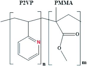
The surface chemistry of a polymer with the desired physical characteristics, such as size, shape, and interfacial features, is the major rationale for a variety of applications while working at the nanoscale. Poly(2-vinylpyridine-block-methylmethacrylate), P(2VP-MMA), is an amphiphilic diblock copolymer with distinctly different polarities of each block (Fig. 2). The total molar mass of the block copolymer and the relative ratio of the blocks have a huge impact on the morphology of films prepared with these block copolymers.BCPs have the ability to self-assemble in the form of micelles in a suitable medium, depending upon the relative compatibility of the individual block with the surrounding solvent. For instance, toluene is a good solvent for PMMA but a non-solvent for P2VP; therefore, the micelles of their BCPs will be formed with an insoluble core containing P2VP protected by a PMMA corona (Fig. 1). The presence of basic nitrogen in the P2VP matrix of the copolymer makes it an excellent candidate for the fabrication of nanoparticles in the polymer domain.
The current study is devoted to variations in the morphology of films of P(2VP-MMA) as a function of total molar mass, relative individual block length, and composition of BCPs, as well as the polarity of casting solvent and substrate, followed by variations in the morphology of BCP films by incorporation of NPs in the polymer domain. Finally, the effect of thermal annealing on BCP films is discussed.
3.1. Surface morphology of films of P(2VP-MMA) and P(2VP-MMA)-AuNPs
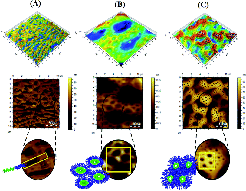
As a first step of surface morphology studies, polymer and polymer coated AuNPs were cast onto Si wafers from toluene. The coating was accomplished by air drying the surface for 48 h Fig. 3 illustrates the surface morphology of films obtained on Si wafers by casting several P(2VP-MMA) BCPs from toluene that have different total molar masses and compositions of individual blocks. Different surface topographies were obtained that require quantitative assessment for the development of any correlation with the composition of the polymers. The factors controlling the phase separation of the copolymers in the formation of films by solvent evaporation include different surface free energies and the comparative solubility of different segments in the casting solvent, and polymer–air and/or polymer–substrate interactions. All three factors collectively dictate the final morphology of the copolymer films.39,40 Furthermore, incorporating AuNPs affected the topography of the polymer by enlarging the phase domain (Fig. 1).The BCPs under study could be compared with regard to couple of parameters. The first comparison could be BCPs with a similar total molar mass but different composition. P(2VP3-MMA97) and P(2VP15-MMA85) have comparable molar masses; however, their chemical compositions are significantly different. Flatter surfaces with a lamellar structure containing undefined grooves between the lamellae were obtained with P(2VP3-MMA97), as shown in Fig. 3A. The block length of P2VP is shorter compared to PMMA. In this case; therefore, they are arranged like threads instead of spherical micelles. Conversely, continuous hexagonal structures with a pore size of 28 nm were obtained with P(2VP15-MMA85), that has a considerably longer P2VP block length (Fig. 3B). The second comparison could be BCPs having similar P2VP block length, but different total molar masses. In this context, P(2VP15-MMA85) and P(2VP10-MMA90) have similar P2VP block lengths; however, the total molar mass of the latter is higher. The morphologies of the films obtained with both are similar; nonetheless, smaller cylindrical nanogrooves with an average pore size of 10 nm are obtained for P(2VP10-MMA90) compared to 28 nm for P(2VP15-MMA85) (Fig. 3B and C).
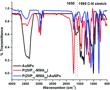
The grooves and ridges observed in films might be pores of the block copolymers formed during the process of micelle formation. This hypothesis is supported by a comparison of the topographical images obtained for P(2VP-MMA) (Fig. 3) and P(2VP-MMA)-AuNPs (Fig. 5). The nanoparticles incorporated in the polymer micelles became brighter and enlarged in domain size. The basic nitrogen in the polymer backbone reacts with AuNPs that results in a swelled core of the micelle. The assumption that AuNPs are incorporated into the P2VP core of the micelles is also supported by FTIR analysis.29 FTIR spectra of AuNPs, P(2VP-MMA), and P(2VP-MMA)-AuNPs are demonstrated in Fig. 4. The C–N stretch peak of P2VP at 1595 cm−1 disappeared and a new peak at 1650 cm−1 appeared that indicates the interaction of AuNPs with P2VP.
An AFM topographical analysis showed that the size of the nanoparticles fabricated with different copolymers is in the order of P(2VP10-MMA90) < P(2VP15-MMA85) < P(2VP3-MMA97) (Fig. 5). This is a clear indication that pores in P(2VP10-MMA90) are smaller compared to those in P(2VP15-MMA85) followed by P(2VP3-MMA97).
Furthermore, the obtained Rsk values for P(2VP3-MMA97), P(2VP15-MMA85) and P(2VP10-MMA90) are 1.55, 3.28 and 2.08, respectively (Fig. 6A). These values clearly indicate unsymmetrical surfaces containing grooves. The lowest value of Rsk for P(2VP3-MMA97) compared to the other two BCPs indicates a comparatively smoother surface. The increase in the mole fraction of P2VP with a similar molar mass resulted in higher Rsk values, which means a rough surface [compare P(2VP3-MMA97) and P(2VP15-MMA85)]. Moreover, the slightly lower Rsk values obtained for P(2VP10-MMA90) compared to P(2VP15-MMA85) might be attributed to a longer PMMA block with a similar P2VP block length. The roughness of the film decreases with incorporation of gold nanoparticles, as evidenced by decreased Rsk values (Fig. 6B).
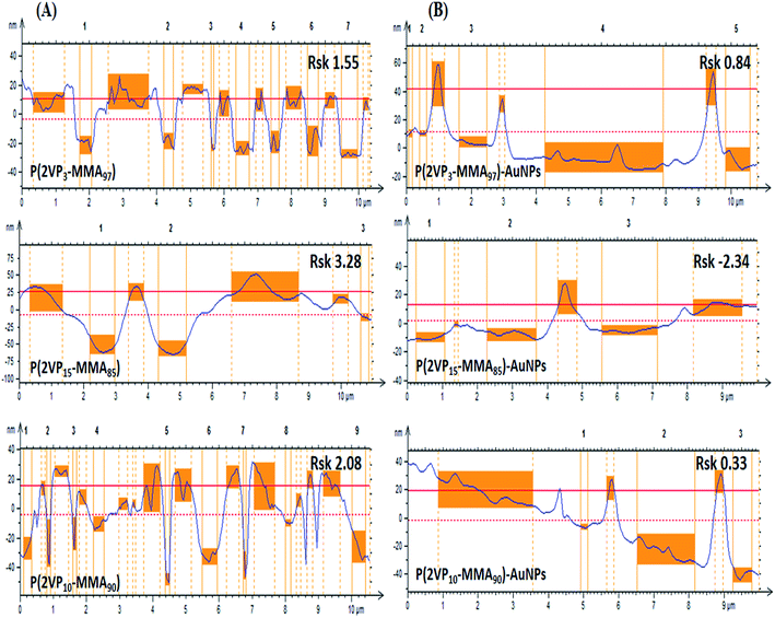 | ||
| Fig. 6 Amplitude roughness profiles obtained by AFM of (A) P(2VP-MMA), and (B) P(2VP-MMA)-AuNPs at a horizontal scale of 10 × 10 μm. All samples were cast from toluene onto silicon wafers. | ||
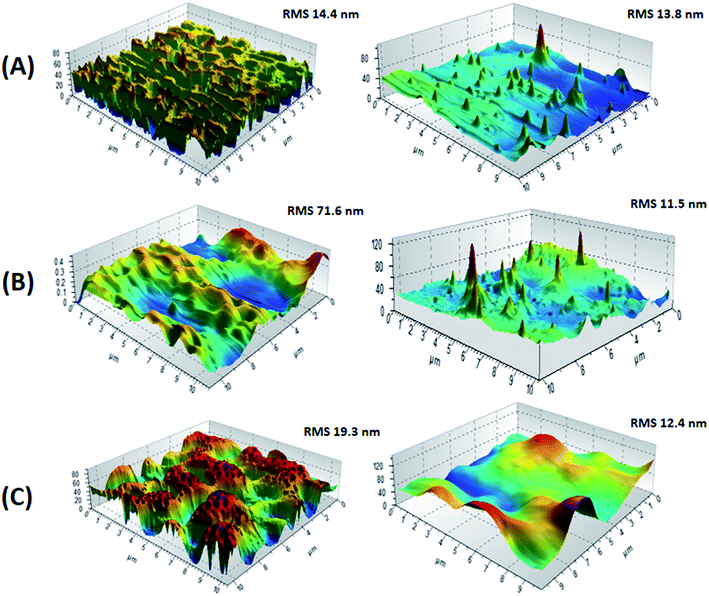
The disparity of the morphology of films for P(2VP-MMA) and P(2VP-MMA)-AuNPs might be attributed to a distinct conformation with different surfaces. Surface roughness factors are quantitatively evaluated for both P(2VP-MMA) and P(2VP-MMA)-AuNPs by analysis of the AFM images. The roughness root mean square (RMS) was calculated at 10 μm length scales. The phase image of P(2VP15-MMA85) was found to have the roughest surface with an RMS value of 71.6 nm at 10 μm (Fig. 7). The smoother surfaces of films obtained with P(2VP3-MMA97) and P(2VP10-MMA90) are evident with RMS values of 14.4 and 19.3 nm, respectively.
Incorporation of AuNPs resulted in a decrease in the RMS values. The decrease is very pronounced in the case of P(2VP15-MMA85) that has the roughest film surface, by a factor of 6.2. The other two polymers, namely P(2VP3-MMA97) and P(2VP10-MMA90), showed a reduction in RMS values by factors of 1.04 and 1.56, respectively. A comparison of the reduction in RMS values with incorporation of AuNPs is demonstrated in Fig. 8. Hence, P(2VP15-MMA85) was selected for further studies on the effects of various experimental parameters on the morphology of the film because of its smoother surface and intermediate morphology compared to the other samples under study.
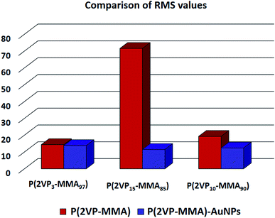 | ||
| Fig. 8 A comparison of RMS values obtained through AFM for P(2VP-MMA) and P(2VP-MMA)-AuNPs. All samples were cast from toluene onto silicon wafers. | ||
3.2. Size of the P(2VP-MMA) micelles in toluene and P(2VP-MMA)-AuNPs
An analysis of the trend in the sizes of the micelles on account of the total molar mass and molar mass of individual blocks of P(2VP-MMA) in toluene and the effect of incorporation of AuNPs in the micelles is demonstrated in Fig. 9. As mentioned earlier, a comparison of the three BCPs under study can be made with two parameters. First would be similar total molar mass but different chemical composition (P2VP block length). The samples that meet this criterion are P(2VP3-MMA97) and P(2VP15-MMA85). The size of the micelles increases with the length of the P2VP core. The second viable comparison could be different total molar mass but similar chemical composition. P(2VP15-MMA85) and P(2VP10-MMA90) have different total molar masses but comparable chemical composition (P2VP block length). The size of the micelles is found to be higher for the BCPs with a higher total molar mass but comparable P2VP block length (Fig. 9A). Furthermore, the incorporation of metal NPs in the micelles resulted in decreased average sizes; however, the trend remains the same (Fig. 9B).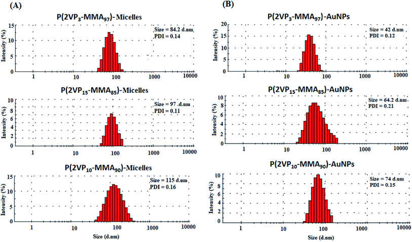 | ||
| Fig. 9 Size distribution by intensity of (A) P(2VP-MMA) micelles in toluene; and (B) P(2VP-MMA)-AuNPs. | ||
3.3. Comparison of films of P(2VP-MMA) micelles and P(2VP-MMA)-AuNPs by scanning electron microscopy
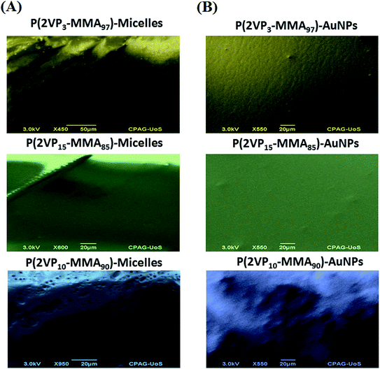
SEM images support the data obtained by AFM topographic images. P(2VP3-MMA97) forms elongated lamellar polymer blocks without any definite shape, whereas P(2VP10-MMA90) forms deeper groves and ridges. P(2VP15-MMA85) shows a much smoother surface at a scale of 20 μm (Fig. 10). The smoothness of the films increased with incorporation of nanoparticles in all cases, but is more pronounced in the case of P(2VP15-MMA85). The SEM imaging results endorse the results obtained by AFM.3.4. Effect of casting solvent on surface morphology
Casting solvent might have different compatibilities for each segment of the BCP; hence, it will have a huge impact on the morphology of BCP films.3,23,25 The phase exhibiting a lower solubility in the solvent extends beyond the phase with higher solubility, leading to variable morphology of the cast films from different solvents. In this context, three different solvents (toluene, chloroform and ethyl acetate) varying in their polarity are employed to prepare the casting solution. Toluene is a good solvent for PMMA but a non-solvent for P2VP, chloroform is a good solvent for both PMMA and P2VP, whereas ethyl acetate is a good solvent for P2VP but a non-solvent for PMMA.Fig. 11 depicts AFM topographical images of P(2VP15-MMA85) copolymer films cast from toluene, chloroform and ethyl acetate solutions. The surface morphology of the BCP film cast from toluene was rich in the P2VP phase and poor in PMMA, showing a regular hexagonal pattern. Toluene is a non-polar solvent that has preferred solvation for PMMA compared to P2VP. Hence, the P2VP phase was deposited earlier than PMMA and resulted in a unique morphology with P2VP protrusions over the PMMA domains. The light region represents the P2VP phase whereas the PMMA phase is represented by the dark region. The low surface energy of P2VP stimulates the formation of a continuous phase on the surface while PMMA has to be a dispersed phase. On the other hand, film coated from a chloroform solution produces a spread morphology without preference for any segment because of the non-preferential solvation of both segments. On the same lines, a solvent with higher polarity would have preferential solvation for P2VP compared to PMMA. Consequently, PMMA is deposited earlier compared to P2VP and results in a unique morphology with PMMA protrusions over a P2VP domain. In addition, P2VP has a lower surface free energy compared to PMMA; hence, the P2VP phase has a higher affinity for the air–polymer surface to obtain a continuous state.
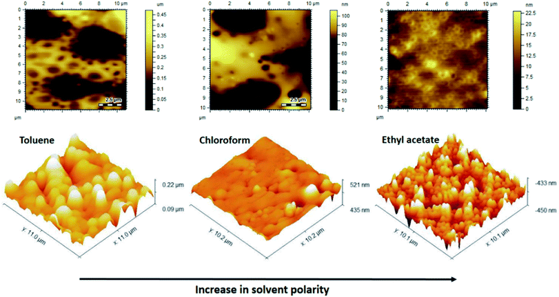 | ||
| Fig. 11 AFM images of P(2VP15-MMA85) cast from solvents of different polarity on Si wafers demonstrating solvent selectivity for the surface morphology. | ||
3.5. Effect of substrate on surface morphology
As a next step, the effect of substrate on the morphology of films is evaluated. The long- and short-range interactions at air–polymer and substrate–polymer interfaces resulted in rich interplays and competition. Block-selective segregation at the substrate will occur when the wetting component provides the lowest interfacial tension or exhibits a specific affinity for the substrate, so-called substrate-induced ordering.41–43 Herein, three types of substrates are used that have distinct interactions with the PMMA and P2VP segments. Chloroform is selected as the casting solvent since it has no preferential solvation for any of the segments of BCP.AFM 3D phase images of the P(2VP15-MMA85) copolymer films on mica, silicon, and graphite surfaces cast from chloroform are presented in Fig. 12. Mica has hydrophilic and highly polar ions, Si is hydrophilic and moderately polar, whereas graphite (HOPG) is non-polar and hydrophobic in nature. It is apparent that the shape and size of the copolymer films coated on different substrates are dissimilar due to the different attractions of P2VP and PMMA for different substrates. P(2VP15-MMA85) contains a long chain of PMMA compared to P2VP. Therefore, a smooth surface is obtained on HOPG due to high hydrophobic–hydrophobic interaction. A slightly thick film is formed on silicon compared to mica. The reason might be the strong interaction of the P2VP block with the highly polar mica surface. The mica substrate contains silicon–hydroxyl bonds that interact with P2VP blocks, rendering a P2VP block distribution over a mica substrate. A thicker surface is obtained on mica compared to HOPG because of the long chains of the PMMA block. The silicon substrate has no preferential interaction with either PMMA or P2VP blocks. However, P2VP has lower free energy compared to PMMA that results in enrichment of P2VP at the air–polymer interface in order to minimize the air–polymer interfacial free energy. Hence, a higher P2VP mole fraction is observed at the air–polymer interface compared to the bulk that results in the appearance of a lamellar structure parallel to the surface. Furthermore, the grain height obtained on mica (42.3 nm) is higher compared to silicon (26.8 nm), due to different surface energies and polymer–substrate interactions.
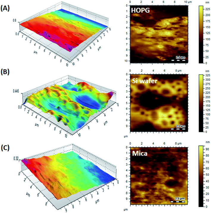 | ||
| Fig. 12 AFM 3D phase images of P(2VP15-MMA85) cast from chloroform on substrates of varying polarity, demonstrating substrate selectivity for the surface morphology: (A) HOPG, (B) Si wafer, (C) mica. | ||
3.6. Thermal annealing and surface morphology
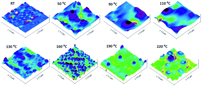
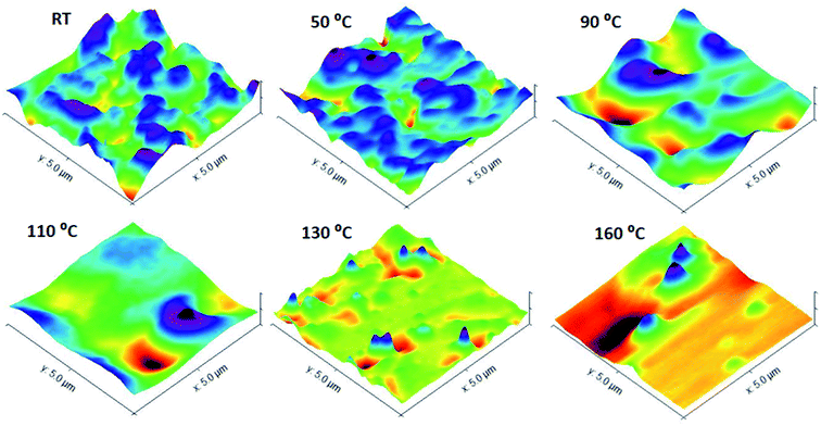
Annealing at different temperatures can have an enormous effect on the morphology of the surface of BCP films. In the following discussion, the effects of thermal annealing in a temperature range from 50 to 230 °C for about 30 min on the surface morphology of the P(2VP-MMA) and P(2VP-MMA)-AuNPs copolymer films cast from chloroform on Si wafers are elaborated (Fig. 13 and 14). Film ordering has been improved considerably by thermal annealing. The poor ordering of films prior to thermal annealing might be attributed to differences in solubility and surface energy of each segment of the block copolymers. Additionally, the rapid evaporation of solvents might hamper the proper alignment of different segments. The PMMA and P2VP phase regions have approximately the same area in the untreated samples; however, an augmented P2VP region is observed after the films have been annealed at higher temperature. The annealing temperature of 70 °C is higher than the glass transition temperature of P2VP (50 °C) and lower than the glass transition temperature of PMMA (100 °C); hence, P2VP segments are more mobile, resulting in an increased P2VP domain. Furthermore, with annealing of the films at 110 °C, a temperature above the glass transition temperature of both P2VP and PMMA, the higher immiscibility of both segments is evident (Fig. 13). The PMMA domain increased again due to the enhanced mobility of the PMMA segment beyond its Tg. Moreover, the slight melting of the PMMA block above 110 °C and complete melting beyond 160 °C (i.e. the melting point of PMMA) resulted in dewetting of the polymer.To confirm the phenomena of the effects of thermal annealing on P(2VP15-MMA85) film morphology, P(2VP15-MMA85)-AuNPs films cast from chloroform onto Si wafers were also annealed. The presence of metallic nanoparticles in the P2VP domain resulted in additional absorption of heat at 70 °C; therefore, the P2VP phase extended more compared to P(2VP15-MMA85). Furthermore, the PMMA segment started to expand above 110 °C, resulting in an increase in the PMMA domain. Finally, the whole morphology was disturbed completely at 160 °C (Fig. 14).
4. Conclusions
AFM is a powerful technique for the characterization of self-assemblies of block copolymers. This study is focused on manipulating the morphologies of P(2VP-MMA) copolymer films by varying the total molar mass of BCP, individual block lengths, the solvent used for casting and the substrate. Surface roughness and thickness increased with an increase in the molecular weight of the polymer. Completely different morphologies of films are obtained by casting the same polymer from solvents of different polarity. The morphology of the films cast on different substrates showed a rough surface for hydrophilic Si wafers and mica, whereas a flatter surface was obtained for hydrophobic graphite, due to the peculiar surface interactions of the different substrates. Furthermore, thermal annealing induced improved ordering in the films. The area of the P2VP domain increased by annealing above 70 °C up to 110 °C compared to the PMMA domain, due to the increased mobility of P2VP above its Tg value. Beyond 110 °C, the area of the PMMA domain also started to increase due to the increased mobility of the PMMA segment above its Tg value. Finally, the incorporation of AuNPs in the P2VP domain enlarged the domain size and confirmed the morphological selectivity of the films.Conflicts of interest
Authors declare no conflicts of interest.References
- G. Li, V. Shrotriya, J. Huang, Y. Yao, T. Moriarty, K. Emery and Y. Yang, Nat. Mater., 2005, 4, 864 CrossRef CAS.
- W. Ma, C. Yang, X. Gong, K. Lee and A. J. Heeger, Adv. Funct. Mater., 2005, 15, 1617–1622 CrossRef CAS.
- M. Campoy-Quiles, T. Ferenczi, T. Agostinelli, P. G. Etchegoin, Y. Kim, T. D. Anthopoulos, P. N. Stavrinou, D. D. Bradley and J. Nelson, Nat. Mater., 2008, 7, 158 CrossRef CAS PubMed.
- A. Ryan and I. Hamley, in The physics of glassy polymers, Springer, 1997, pp. 451–497 Search PubMed.
- V. Mishra, G. H. Fredrickson and E. J. Kramer, ACS Nano, 2012, 6, 2629–2641 CrossRef CAS PubMed.
- N. Hoogesteijn von Reitzenstein, X. Bi, Y. Yang, K. Hristovski and P. Westerhoff, J. Appl. Polym. Sci., 2016, 133, 43811 CrossRef.
- D. A. Hajduk, P. E. Harper, S. M. Gruner, C. C. Honeker, G. Kim, E. L. Thomas and L. J. Fetters, Macromolecules, 1994, 27, 4063–4075 CrossRef CAS.
- H. Xiang, K. Shin, T. Kim, S. Moon, T. McCarthy and T. Russell, J. Polym. Sci., Part B: Polym. Phys., 2005, 43, 3377–3383 CrossRef CAS.
- M. A. Chavis, D. M. Smilgies, U. B. Wiesner and C. K. Ober, Adv. Funct. Mater., 2015, 25, 3057–3065 CrossRef CAS PubMed.
- M. Templin, A. Franck, A. Du Chesne, H. Leist, Y. Zhang, R. Ulrich, V. Schädler and U. Wiesner, Science, 1997, 278, 1795–1798 CrossRef CAS PubMed.
- R. J. Spontak, M. C. Williams and D. A. Agard, Polymer, 1988, 29, 387–395 CrossRef CAS.
- R. J. Spontak and A. H. Windle, J. Polym. Sci., Part B: Polym. Phys., 1992, 30, 61–69 CrossRef CAS.
- E. L. Thomas, D. B. Alward, D. J. Kinning, D. C. Martin, D. L. Handlin Jr and L. J. Fetters, Macromolecules, 1986, 19, 2197–2202 CrossRef CAS.
- K. Paeng, R. Richert and M. Ediger, Soft Matter, 2012, 8, 819–826 RSC.
- L. Cui, Y. Ding, X. Li, Z. Wang and Y. Han, Thin Solid Films, 2006, 515, 2038–2048 CrossRef CAS.
- S. Roy and A. Sharma, J. Colloid Interface Sci., 2015, 449, 215–225 CrossRef CAS PubMed.
- K. Letchford and H. Burt, Eur. J. Pharm. Biopharm., 2007, 65, 259–269 CrossRef CAS PubMed.
- F. S. Bates and G. H. Fredrickson, Annu. Rev. Phys. Chem., 1990, 41, 525–557 CrossRef CAS PubMed.
- Y. Mai and A. Eisenberg, Chem. Soc. Rev., 2012, 41, 5969–5985 RSC.
- A. Choucair and A. Eisenberg, Eur. Phys. J. E, 2003, 10, 37–44 CrossRef CAS PubMed.
- T. Ohta and K. Kawasaki, Macromolecules, 1986, 19, 2621–2632 CrossRef CAS.
- V. Abetz and P. F. Simon, in Block copolymers I, Springer, 2005, pp. 125–212 Search PubMed.
- N. Wu, A. Zheng, Y. Huang and H. Liu, J. Appl. Polym. Sci., 2007, 104, 1010–1018 CrossRef CAS.
- G. Li, V. Shrotriya, Y. Yao and Y. Yang, J. Appl. Phys., 2005, 98, 043704 CrossRef.
- E. Verploegen, R. Mondal, C. J. Bettinger, S. Sok, M. F. Toney and Z. Bao, Adv. Funct. Mater., 2010, 20, 3519–3529 CrossRef CAS.
- J. Jo, S. S. Kim, S. I. Na, B. K. Yu and D. Y. Kim, Adv. Funct. Mater., 2009, 19, 866–874 CrossRef CAS.
- T. Lohmueller, E. Bock and J. P. Spatz, Adv. Mater., 2008, 20, 2297–2302 CrossRef CAS.
- J. Chai, D. Wang, X. Fan and J. M. Buriak, Nat. Nanotechnol., 2007, 2, 500 CrossRef PubMed.
- S. Rahim, A. Rauf, S. Rauf, M. R. Shah and M. I. Malik, RSC Adv., 2018, 8, 35776–35786 RSC.
- S. Rahim, S. A. Ali, F. Ahmed, M. Imran, M. R. Shah and M. I. Malik, J. Nanopart. Res., 2017, 19, 259 CrossRef.
- S. Rahim, S. Khalid, M. I. Bhanger, M. R. Shah and M. I. Malik, Sens. Actuators, B, 2018, 259, 878–887 CrossRef CAS.
- J. H. Youk, M.-K. Park, J. Locklin, R. Advincula, J. Yang and J. Mays, Langmuir, 2002, 18, 2455–2458 CrossRef CAS.
- A. Nasir, A. Kausar and A. Younus, Polym. Plast. Technol. Eng., 2015, 54, 325–341 CrossRef CAS.
- T. O. Lekesiz, C. Kayran and J. Hacaloglu, Polym. Adv. Technol., 2015, 26, 555–560 CrossRef CAS.
- G. Carotenuto, G. P. Pepe and L. Nicolais, Eur. Phys. J. B, 2000, 16, 11–17 CrossRef CAS.
- Y. Y. Yu, W. C. Chien and S. T. Chen, Polym. Int., 2008, 57, 1369–1376 CrossRef CAS.
- P. M. Carrasco, L. Tzounis, F. J. Mompean, K. Strati, P. Georgopanos, M. Garcia-Hernandez, M. Stamm, G. Cabañero, I. Odriozola, A. Avgeropoulos and I. Garcia, Macromolecules, 2013, 46, 1860–1867 CrossRef CAS.
- C. Deraedt, L. Salmon, S. Gatard, R. Ciganda, R. Hernandez, J. Ruiz and D. Astruc, Chem. Commun., 2014, 50, 14194–14196 RSC.
- S. Jönsson, J. Birgerson, X. Crispin, G. Greczynski, W. Osikowicz, A. D. Van Der Gon, W. R. Salaneck and M. Fahlman, Synth. Met., 2003, 139, 1–10 CrossRef.
- M. Yeow, Y. Liu and K. Li, J. Appl. Polym. Sci., 2004, 92, 1782–1789 CrossRef CAS.
- E. P. S. Tan and C. T. Lim, Appl. Phys. Lett., 2004, 84, 1603–1605 CrossRef CAS.
- X. Han, C. Luo, Y. Dai and H. Liu, J. Macromol. Sci., Part B: Phys., 2008, 47, 1050–1061 CrossRef CAS.
- G. Liu, S. Ji, K. O. Stuen, G. S. W. Craig, P. F. Nealey and F. J. Himpsel, J. Vac. Sci. Technol., B, 2009, 27, 3038–3042 CrossRef CAS.
| This journal is © The Royal Society of Chemistry 2019 |

![[thin space (1/6-em)]](https://www.rsc.org/images/entities/char_2009.gif) :
: