 Open Access Article
Fabrication of a biconnected structure PVB porous heddle via thermally induced phase separation
Yunying Luoa,
Yangyang Xua,
Feng Wangab,
Chengcai Lia,
Jieqi Wanga,
Mengtian Jinc,
Hailin Zhu *ab and
Yuhai Guo
 *a
*a
aZhejiang Provincial Key Laboratory of Fiber Materials and Manufacturing Technology, Zhejiang Sci-Tech University, Hangzhou, 310018, China. E-mail: gyh@zstu.edu.cn; zhhailin@163.com
bZhejiang Kertice Hi-tech Fluor-material Co. Ltd, Wuxing District, Huzhou, 313000, China
cChina Textile Academy Ltd, Chaoyang District, Beijing, 100025, China
First published on 10th May 2019
Abstract
Herein, a porous heddle of poly(vinyl butyral) (PVB) was successfully prepared by thermally induced phase separation with PEG400. A phase diagram of PVB was presented, and the effects of various parameters, such as polymer concentration, extrusion temperature, quenching temperature and take-up speed, on the morphology and properties of the PVB porous heddle were investigated. The pore size and porosity of the heddle increase as the extrusion temperature increases. Furthermore, upon increasing the quenching temperature during the TIPS process, the pore size and mechanical properties decrease, whereas porosity increases. In addition, due to the substantially unchanged crystallinity of the PVB heddle, the tensile strength increases since porosity decreases with the increasing take-up speed. The porosity of the prepared PVB porous heddle reached up to 74.63% when the PVB concentration, the quenching temperature and the extrusion temperature were 20 wt%, 0 °C and 170 °C, respectively. Thus, this porous heddle exhibiting a biconnected structure and significant mechanical properties is promising in the field of porous carrier materials.
1 Introduction
Thermally induced phase separation (TIPS) is a useful process to fabricate microporous polymer membranes with diverse morphologies. Typically, the TIPS process involves heating a polymer/diluent mixture at high temperatures to prepare a homogeneous solution and then cooling the solution to low temperatures for phase separation.1,2 The selected diluent is closely related to the phase separation behaviors, that is, liquid–liquid (L–L) and solid–liquid (S–L) phase separation. Compared with non-solution phase separation (NIPS) methods, the TIPS process is not only simple but also enables facile control of the membrane structures because it has fewer influencing factors such as diluent, cooling rate, polymer concentration, and additives. This method can be used to form porous materials with narrow pore-size distributions, higher strength, elongation of breakage and porosity, and pliability with much better performance when compared with materials produced via the NIPS method.3–5 Hence, many researchers have paid attention to the study of forming porous materials by TIPS.6–10Poly(vinyl butyral) (PVB) is prepared by reacting polyvinyl alcohol (PVA) with butyraldehyde in an acidic medium. Substantial amounts of unreacted vinyl alcohol units typically remain in the chain;11 PVB is regarded as a random copolymer of vinyl butyral and vinyl alcohol units. The vinyl alcohol unit is polar and hydrophilic, and the vinyl butyral unit is hydrophobic. In addition to being an innocuous and tasteless polymeric material, PVB can endure low temperatures, light, changes in humidity, bacteria, microorganisms, alkali and diluent acid.12 Moreover, it reveals some hydrophilicity because of its hydroxyl groups. Therefore, PVB is an attractive material for preparing porous materials, although there are very few literature reports on the preparation of PVB porous materials using the TIPS process.13 Therefore, investigating the preparation of PVB porous materials is a very important topic, especially because materials with high porosity are used in culturing organisms during sewage treatment processes.
During the preparation of PVB porous materials via the TIPS process, the diluent plays an essential role in influencing the ultimate morphologies and performance of the PVB porous materials. Various diluents have good compatibility with PVB at high temperature; however, most of them are non-water soluble and some are even known to be explosive, decreasing the impact of the porous material for environmental protection. Thus, using an environmentally friendly diluent is of great importance in preparing porous materials. In fact, it should be noted that very little optimisation work has been carried out on the diluents used in synthesizing PVB porous materials via the TIPS process. On the basis of their excellent miscibility with PVB, low volatility, relatively low molecular weights, environmental friendliness and good thermal stability at high temperatures, PEG-containing plasticizers have been used as diluents to prepare PVB hollow fiber membranes by the TIPS method.14–17 Due to the superior performance of the hollow fiber membranes, it is possible to prepare PVB materials with well-developed pore structures, surface areas, adsorption, high strength and elongation of breakage, and chemical stability via TIPS.
The objective of the present study is to investigate the effects of the preparation conditions in the preparation of a biconnected structure PVB porous heddle by the TIPS process. The phase diagram of the PVB-PEG400 system as a function of the polymorphisms, morphology, and properties of the PVB porous heddle is presented as well.
2 Experimental procedure
2.1 Materials
The copolymer poly(vinyl butyral) (PVB) with a viscosity of 5 cps (apply 1 cup) was purchased from Guangdong Yuemei Chemical Co., Ltd. The vinyl butyral and vinyl alcohol parts of the copolymer are 80 and 18 weight percent (wt%), respectively; the residual vinyl acetate part is 2 wt%. Polyethylene glycol (PEG, Mw = 400, hereinafter referred to as PEG400), used as the diluent, was purchased from Aladdin. All chemicals were used without further purification.2.2 Phase diagrams
Appropriate amounts of PVB and PEG400 were weighed into a glass test tube, and the blend was heated and shaken in an oil bath at 170 °C, mixing for 30 min in a nitrogen atmosphere, in order to prepare a homogenous solution. Solid PVB-PEG400 samples were produced after the blend solutions were cooled under liquid nitrogen.In the PVB-PEG400 system, studying the melting point (Tm) is of great importance for determining a suitable temperature to obtain a homogenous PVB-PEG400 system. Also, the glass transition temperature (Tg) is key to terminate coarsening. The Tm and Tg curves were determined photometrically using a Q2000 differential scanning calorimeter (DSC, Zhejiang Zhongda Technical Import Co, Ltd). Samples of PVB powder and different concentrations of solid PVB-PEG400 were used, and the measurements were performed by heating from 30 °C to 175 °C under an inert nitrogen atmosphere at a flow rate of 50 ml min−1. After waiting for 3 min to ensure complete melting and equilibration, the samples were cooled to room temperature at a rate of 10 °C min−1.
The cloud point (Tcloud) is the temperature of the polymer separate diluent, which is very important in addition to the phase separation mechanism. A small amount of prepared solid sample was heated on the THMS-600 hot stage of a LEICA DMLP TL&RT thermo-optical microscope (Linkam UK/leica Germany) to 170 °C for 3 min and then cooled to 30 °C at a rate of 3 °C min−1. Tcloud was determined by monitoring the appearance of turbidity under an optical microscope. The average values were determined by measuring at least five times.
2.3 Preparation of PVB porous heddles
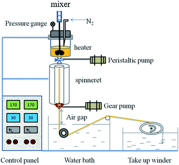
PVB porous heddles were prepared using laboratory self-assembly equipment (XNR-400A melt flow indexer, Shanghai Hesheng Instruments Technology Co. Ltd) with the following procedures (Fig. 1). PVB-PEG400 blending samples were fed into the heater, heated to respective temperatures of 150 °C, 160 °C, or 170 °C, and thermally insulated for a period of time. Short thermal insulation was employed in the sealed furnace chamber to ensure complete and even mixing. After holding at this high temperature for 10 min, the homogeneous polymer solution was fed to a spinneret under a peristaltic pump. The pressure over the polymer solution was in the range of 0.0325 to 0.04 MPa; to obtain the same extrusion rate, a higher pressure was needed for the greater molecular weight of PEG and the higher concentration of PVB due to their greater viscosity. The diameter of the spinneret was 1.6 mm. Then, the blending solution was extracted to acquire the nascent heddle after immersion in a water bath at 0 °C, 30 °C, or 40 °C at an air gap distance of zero and was finally wound by a take-up winder.The PVB heddles were extruded from the spinneret and wound on a take-up winder after being placed in water baths at different temperatures to induce phase separation and solidify the porous heddles. The variables in the spinning process were PVB concentration, extrusion temperature, quenching temperature, and take-up speed. The air gap distance of the process was zero. The diluent remaining in each heddle was extracted by immersing it in water for 24 h and freeze-drying for 48 h. In the end, the PVB-PEG400 microporous heddles were obtained.
 | (1) |
3 Results and discussion
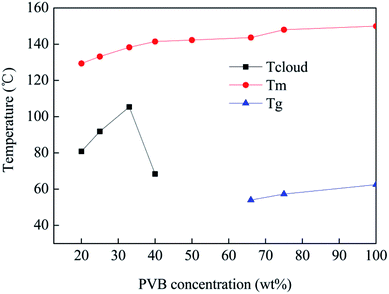
3.1 Phase diagrams
Fig. 2 shows the phase diagram of the PVB-PEG400 system, including the Tm, Tg and Tcloud of PVB-PEG400. There is a vital gap between phase differences, demonstrating that the morphology of the heddle transitions is a function of PVB concentration, whereas the Tm clarifies the suitable temperature for a homogenous solution.The Tm curve is above the Tcloud curve, which indicates that in the process of L–L phase separation, the local PVB concentration of polymer-rich phase must have been greater than the critical concentration to offer enough time for droplet formation. In the PVB-PEG400 system, with increasing concentration of PVB, not only did the Tg dramatically increase, but the Tcloud also gradually increased initially and then decreased. As can be seen in Fig. 2, the Tcloud increases in the range from 68 °C to 105 °C and the Tg decreases from 62 °C to 54 °C. The influence of PEG400 on the Tg cannot be neglected for the interaction of the blend. This can mainly be attributed to the synergistic effect of the compatibility and agglomeration of PEG400.15,16 Better compatibility is obtained and ensembles form because the aggregation of excess PEG400 surpasses the solidification of the PVB. Therefore, the Tg decreases with increasing PEG content. When the PEG400 content is less than 66 wt%, PVB is inclined to solidify due to the poor compatibility between PVB and PEG400; thus, Tg increases.
Also, with increasing PVB concentration, the phase separation is more inclined to occur at a higher temperature in the binary PVB-PEG400 system. Because the viscosity of the blend solution increases, a three-dimensional network structure forms between molecules, preventing movement of the molecular chains. Therefore, the PVB-PEG400 system requires more condenser depression to solidify with a high concentration of PVB. Meanwhile, phase inversion occurs with a PVB concentration of 33 wt%. Generally, the L–L phase inversion mechanisms are nucleation and growth (NG) or spinodal decomposition (SD) when the cooling temperature reaches the binodal line L–L phase.18–20 NG occurs in the metastable region (i.e. between the binodal and spinodal lines in the phase diagram) while SD occurs in the unstable region (under the spinodal line in the phase diagram).19 Depending on the mechanism of phase inversion occurring during the heddle formation process, different morphologies can be obtained. It is difficult to form biconnected network structures due to the heterogeneous solution at high temperature when the concentration is above 33 wt%.
3.2 Morphology
It is interesting to discover a process that induces biconnected structures with TIPS. During the preparation of PVB porous heddles using PEG400, a L–L phase separation mechanism leads to polymer-rich and polymer-lean phases, respectively, resulting in PVB porous heddles with biconnected structures. Because the blend solution can be brought into different regions in the phase diagram by varying the composition and cooling rate, the morphology of a PVB porous heddle is directed significantly by the PVB concentration, quenching temperature and extrusion temperature.3.3 PVB porous heddles
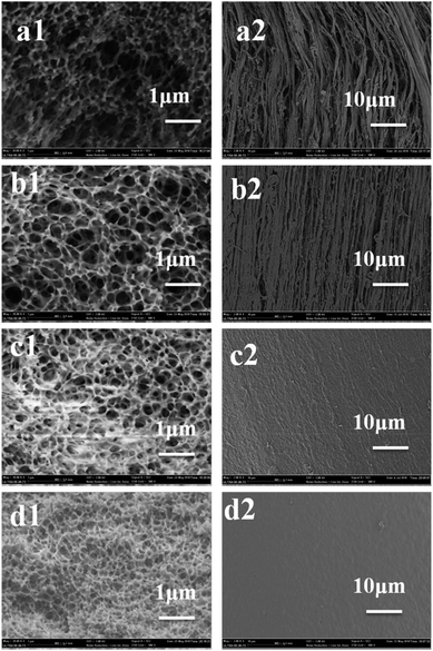
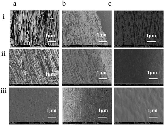
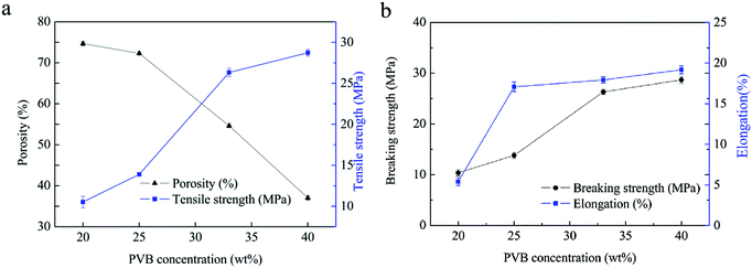
As can be seen in the SEM images, most of the heddles had biconnected structures. The biconnected structure morphology is the typical structure of L–L phase separation via binodal separation. However, the pore size changes from the inner part to the surface. Particularly, because the surface structures of the porous heddles are in direct contract with the water in the coagulation bath, the pore sizes of the droplets are small due to the higher cooling rate compared with the inner lumen part, which is still in contact with the melt blending solution after spinning.Fig. 3 shows the three-dimensional morphologies at a quenching temperature of 0 °C. Fig. 3(a1–d1) and (a2–d2) show the cross sections and top surface morphologies of the PVB porous heddles. The pore size of the heddles shows a decreasing tendency with increasing PVB concentration. As shown in Fig. 3(a1–d1), the PVB heddle shows a more biconnected structure at a low concentration due to the poorer compatibility between PVB and PEG400; meanwhile, the structure of the PVB heddles transforms from a honeycomb structure to a non-penetrating structure with a PVB concentration of 40 wt%. It can be seen that the pore size at a PVB concentration of 33 wt% is smaller than that at 20 wt%. In fact, this phenomenon, which depends on the preexistence of the phase diagram and viscosity in the blend solution,15,16 is directly proportional to PVB concentration in the PVB-PEG400 system. According to the phase diagram in Fig. 2, 33 wt% is the concentration of the phase inversion point; this indicates that a non-penetrating structure followed by a biconnected structure will be thermally induced as the temperature decreases when the PVB concentration is higher than 33 wt%, while only a honeycomb structure will be obtained as the temperature decreases when the PVB concentration is lower than 33 wt%. The PEG400-rich phase needs more time to coarsen due to the fact that the gap between Tcloud and Tg increases with increasing PVB concentration in the range of 20 wt% to 33 wt% in Fig. 2. In addition, it is difficult to instantly form larger droplets with greater viscosity at a higher concentration. On the basis of the above two reasons, discontinuous structures occur in the TIPS process at a PVB concentration of 40 wt%. As can be seen in Fig. 3(a2–d2), the pore size decreases as the PVB concentration increases due to the smaller chance of forming large droplets under constant supercooling temperature at a higher PVB concentration. Furthermore, the number of pores decreases with increasing PVB concentration due to a sudden exchange of PEG400–water and L–L separation. During the TIPS process (Fig. 1), the PVB dissolves in the diluent at high temperature, and a homogenous melting blend is formed. Once the blend solution enters the water, the PVB-rich phase gathers on the surface of the heddle and the PEG400-rich phase becomes porous, leading to greater enhancement of the PVB concentration and a denser top surface morphology with increasing PVB concentration.21,22
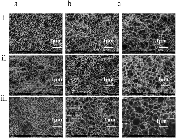
The blend polymer solution–coagulation bath interface is of great importance for determining the final heddle morphology, and the quenching temperature controls the heddle structure dramatically. We observed that the pore size decreased with increasing quenching temperature (Fig. 4). On the one hand, this results from the fact that the transfer is enhanced with increasing quenching temperature. Furthermore, the PEG400 moves to the heddle surface from the substrate,25 which consequently increases the polymer concentration and decreases the heddle pore size in the cross section. On the other hand, the growth process of the droplet shortens at higher quenching temperatures; therefore, a smaller pore size is obtained at a faster cooling rate.26
Surface SEM images of the heddle samples prepared at different quenching temperatures are shown in Fig. 5. With increasing quenching temperature, the pore sizes in the heddle surfaces increase, the number of pores decreases slightly, and the shapes of the pores become more regular. Because the mass transmission rate in 40 °C quenching water is faster than in 0 °C water, the cooling rate of the PVB-PEG400 blending solution increases with decreasing quenching temperature; also, the PVB macromolecular chains have little time for arrangement,27,28 which decreases the pore sizes of the biconnected structures and increases the number of micropores to form heddles with biconnected structures. The driving force of L–L phase separation decreases as the gap between the Tm of the PVB-PEG400 blending solution and the quenching temperature decreases.29 That is to say, the magnitude of this driving force is positively relatived to the supercooling degree. Generally, L–L phase separation and the solidification of the PVB-rich phase are the two competitive factors affecting the coarsening process, thus generating heddle morphologies. When the coarsening temperature falls between the binodal decomposition and spinodal decomposition regions, and when the supercooling degree is increased by the decreased quenching temperature, a faster solidification rate of PVB-rich phase leaves a shorter time for the PEG-lean phase to grow; this results in small pore sizes, as shown on the heddle surfaces (Fig. 5).30,31 Namely, when the quenching temperature decreases, the size of the droplets decreases due to the fact that slower cooling rates give the polymer chains much less opportunity to disentangle during glass transition. In contrast, larger pore sizes are formed with longer coarsening times.
The changes in the PVB porous heddle biconnected structures and the pore sizes are affected by the extrusion temperature and quenching temperature. In essence, the changes are influenced by the synergistic effects of the PVB concentration and cooling rate.
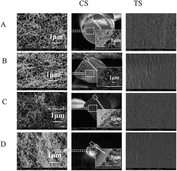
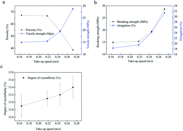
When the take-up speed is lower than 0.218 m s−1, the cross-sectional morphologies remain similar (Fig. 6, CS). All the samples present biconnected structures; furthermore, the pore size gradually decreases from the interior to the surface, which is an asymmetric structure in the porous heddles. The compact structure arises from the different cooling rates during the L–L phase separation. The cooling rate of the PVB-PEG400 blending solution in the centre is much lower due to the obstruction of the hot PVB-PEG400 blending structure.32 However, when the take-up speed reaches 0.245 m s−1, the asymmetric structure disappears. Instead, the whole cross section manifests a more homogeneous structure, and the pore size of the heddle decreases. Those changes are closely related to two factors. First of all, the cooling rate is essential for the heddle morphology structures.9,29,33 When the take-up speed increases, the diameter of the heddle decreases and the cooling rate increases due to the constant extrusion temperature and quenching temperature.29 The second reason is that the shear force of the blend solution in the spinneret changes with changes in the take-up speed during the spinning process.34,35 Similarly, the take-up speed plays a vital role in the PVB macromolecular state before solidification and then directs the structure, properties, and dimensions of the PVB porous heddle in the TIPS process. Furthermore, there is no obvious difference in the surface structures with different take-up speeds, as shown in Fig. 6, TS; also, the heddles display narrow, uniform porous structures. This illustrates that the effects of the take-up speed on the surface structures are very slight.
Furthermore, the diameters are determined by the take-up speed and the extruding rate of the PVB-PEG400 blend solution. The drawing ratio of the porous heddle increases as the take-up speed increases. It can be seen that the diameters of the heddles decrease with increasing take-up speed (Fig. 6, CS).
3.4 Porosity and mechanical properties
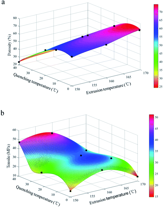 | ||
| Fig. 8 Porosities (a) and mechanical properties (b) of PVB porous heddles produced with different extrusion temperatures and quenching temperatures. | ||
The porosity decreases with increasing quenching temperature (Fig. 8b), which is in good agreement with the observed photosynthetic activity in the SEM morphologies (Fig. 4). This is due to the fact that larger pore sizes are induced on the surfaces of the heddles prepared at relatively higher quenching temperatures (Fig. 5). In addition, the tensile strength decreases with increasing quenching temperature due to the synergy effect between the uniform porous inner substrate and the uneven surface.32 In a word, the microstructure immediately influences the mechanical properties.
4 Conclusion
In this paper, PEG400 was used as an environmentally friendly diluent for PVB porous heddle preparation via the TIPS process. The effects of polymer concentration, extrusion temperature, quenching temperature and take-up speed on the morphologies and properties of the PVB porous heddles were investigated.L–L phase separation occurred under the preparation conditions in this study independent of the PVB concentration and cooling rate. Biconnected structures were prepared during PVB porous heddle preparation. There is more time for droplet growth at a lower cooling rate, resulting in a lower PVB concentration and larger pore sizes. The pore size and porosity decrease and the mechanical properties increase with increasing PVB concentration. In addition, the pore sizes and porosities of the heddles increase when the extrusion temperature increases from 150 °C to 170 °C. By increasing the quenching temperature during the TIPS process, the pore size and mechanical properties decrease while the porosity increases. This indicates that the mechanical properties are negatively related to the porosity with increasing PVB concentration in the TIPS process. The porosity of the prepared PVB porous heddles reached 74.63%, and the mechanical strength was 10.43 MPa when the PVB concentration, the quenching temperature and the extrusion temperature were 20 wt%, 0 °C and 170 °C, respectively. Based on our research, we conclude that the environmentally friendly diluent described here is competitive with PEG400 in preparing PVB porous heddles for porous carrier materials during water treatment applications.
Conflicts of interest
There are no conflicts to declare.Acknowledgements
This work is supported by the National Natural Science Foundation of China (grant no. 21706238) and the Excellent Postgraduate Thesis Program of Zhejiang Sci-Tech University (Grant No. 2018 – XWLWPY-B-03-07, 2018 – XWLWPY-M-03-06).Notes and references
- E. Drioli, A. I. Stankiewicz and F. Macedonio, J. Membr. Sci., 2011, 380, 1–8 CrossRef CAS.
- A. Brunetti, A. Caravella, E. Drioli and G. Barbieri, Chem. Eng. Technol., 2012, 35, 1238–1248 CrossRef CAS.
- P. Bernardo and E. Drioli, Pet. Chem., 2010, 50, 271–282 CrossRef.
- F. Liu, N. A. Hashim, Y. T. Liu, M. R. M. Abed and K. Li, J. Membr. Sci., 2011, 375, 1–27 CrossRef CAS.
- M. H. Gu, J. Zhang, X. L. Wang, H. J. Tao and L. T. Ge, Desalination, 2006, 192, 160–167 CrossRef CAS.
- J. A. Yang, X. L. Wang, Y. Tian, Y. K. Lin and F. Tian, J. Polym. Sci., Part B: Polym. Phys., 2010, 48, 2468–2475 CrossRef CAS.
- H. Sun, K. B. Rhee, T. Kitano and S. I. Mah, J. Appl. Polym. Sci., 2000, 75, 1235–1242 CrossRef CAS.
- X. Han, H. Ding, L. Wang and C. Xiao, J. Appl. Polym. Sci., 2008, 107, 2475–2479 CrossRef CAS.
- Y. K. Lin, G. Chen, J. Yang and X. L. Wang, Desalination, 2009, 236, 8–15 CrossRef CAS.
- S. Rajabzadeh, C. Liang and Y. Ohmukai, J. Membr. Sci., 2012, 423, 189–194 CrossRef.
- F. Shen, X. Lu, X. Bian and L. Shi, J. Membr. Sci., 2005, 265, 74–84 CrossRef CAS.
- M. Gotoh, E. Tamiya and I. Karube, J. Appl. Polym. Sci., 1993, 48, 67–73 CrossRef CAS.
- X. Y. Fu, H. Matsuyama, M. Teramoto and H. Nagai, Sep. Purif. Technol., 2005, 45, 200–207 CrossRef CAS.
- X. Fu, H. Matsuyama, M. Teramoto and H. Nagai, Sep. Purif. Technol., 2006, 50, 363–371 CrossRef.
- Y. R. Qiu, N. A. Rahman and H. Matsuyam, Sep. Purif. Technol., 2008, 61, 1–8 CrossRef CAS.
- Y. R. Qiu and H. Matsuyama, Desalination, 2010, 257, 117–123 CrossRef CAS.
- Y. Qiu, J. Qi and Y. Wei, J. Cent. South Univ., 2014, 21, 2184–2190 CrossRef CAS.
- A. Bottino, G. Capannelli, S. Munari and A. Turturro, J. Polym. Sci., Part B: Polym. Phys., 1988, 26, 785–794 CrossRef CAS.
- D. R. Lloyd, S. S. Kim and K. E. Kinzerb, J. Membr. Sci., 1991, 64, 1–11 CrossRef CAS.
- M. Gu, J. Zhang, X. Wang, H. Tao and L. Ge, Desalination, 2006, 192, 160–167 CrossRef CAS.
- I. Pinnau and W. J. Koros, J. Polym. Sci., Part B: Polym. Phys., 1993, 31, 419–427 CrossRef CAS.
- M. H. V. Mulder, J. O. Hendrikman, J. G. Wijmans and C. A. Smolders, J. Appl. Polym. Sci., 1985, 30, 2805–2820 CrossRef CAS.
- L. U. Kim and C. K. Kim, J. Polym. Sci., Part B: Polym. Phys., 2006, 44, 2025–2034 CrossRef CAS.
- N. Ghasem, M. Al-Marzouqi and N. A. Rahim, Sep. Purif. Technol., 2012, 99, 91–103 CrossRef CAS.
- C. Zhang, Y. Bai, Y. Sun, J. Gu and Y. Xu, J. Membr. Sci., 2010, 36, 216–224 CrossRef.
- F. Shi, J. Ma, P. Wang and Y. Ma, J. Taiwan Inst. Chem. Eng., 2012, 43, 980–988 CrossRef CAS.
- H. Matsuyama, Y. Takida, T. Maki and M. Teramoto, Polymer, 2002, 43, 5243–5248 CrossRef CAS.
- T. H. Xiao, P. Wang, X. Yang, X. H. Cai and J. Lu, J. Membr. Sci., 2015, 489, 160–174 CrossRef CAS.
- X. F. Li and X. L. Lu, J. Appl. Polym. Sci., 2006, 101, 2944–2952 CrossRef CAS.
- S. W. Song and J. M. Torkelson, J. Membr. Sci., 1995, 98, 209–222 CrossRef CAS.
- X. F. Li, G. Q. Xu, X. L. Lu and C. F. Xiao, J. Appl. Polym. Sci., 2008, 107, 3630–3637 CrossRef CAS.
- S. Rajabzadeh, T. Maruyama, T. Sotani and H. Matsuyama, Sep. Purif. Technol., 2008, 63, 415–423 CrossRef CAS.
- X. L. Lu and X. F. Li, J. Appl. Polym. Sci., 2009, 114, 1213–1219 CrossRef CAS.
- G. Fortunato, A. G. Guex, A. M. Popa, R. M. Rossi and R. Hufenus, Polymer, 2014, 55, 3139–3148 CrossRef CAS.
- J. Yang, D. W. Li, Y. K. Lin, X. L. Wang, F. Tian and Z. Wang, J. Appl. Polym. Sci., 2008, 110, 341–347 CrossRef CAS.
- X. Wang, Z. Li, M. Zhang, T. Fan and B. Cheng, RSC Adv., 2017, 7, 10503–10516 RSC.
- H. Zhang, Y. L. Zhao, H. T. Wang, W. Zhong, Q. G. Du and X. M. Zhu, J. Membr. Sci., 2010, 354, 101–107 CrossRef CAS.
- M. Shang, H. Matsuyama and M. Teramoto, Polymer, 2003, 44, 7441–7447 CrossRef CAS.
- D. R. Lloyd, K. E. Kinzer and H. S. Tseng, J. Membr. Sci., 1990, 52, 239–261 CrossRef CAS.
- C. Marega and A. Marigo, Eur. Polym. J., 2003, 39, 1713–1720 CrossRef CAS.
- X. Li, H. Liu and C. Xiao, J. Appl. Polym. Sci., 2013, 128, 1054–1060 CrossRef CAS.
| This journal is © The Royal Society of Chemistry 2019 |

