 Open Access Article
Flexible cupric oxide photocathode with enhanced stability for renewable hydrogen energy production from solar water splitting†
Yang Li *abc and
Kai Luoa
aSchool of Energy and Power, Jiangsu University of Science and Technology, Zhenjiang, Jiangsu 212003, P. R. China. E-mail: yang_li@just.edu.cn
bSchool of Science, Tianjin University, Tianjin, 300072, China
cCollaborative Innovation Center of Chemical Science and Engineering (Tianjin), Tianjin Key Laboratory of Applied Catalysis Science and Technology, State Key Laboratory of Chemical Engineering, School of Chemical Engineering, Tianjin University, Tianjin, 300072, China
First published on 13th March 2019
Abstract
CuO is a promising but unstable photocathode in solar water splitting. Herein, a flexible CuO photocathode is prepared and its degradation mechanisms and stabilization strategies have been discussed. Briefly, we find alkali environment and low light intensity are the critical factors in the stabilization of the CuO photocathode. For practical usage, a composite semiconductor layer, composed of TiO2, La2O3 and NiO, is deposited on the CuO photocathode, which is proved to be effective for enhancing the stabilization of the CuO photocathode. 100% of the photocurrent density has been retained after 20 minutes of continuous illumination. The optimized stable photocurrent density is measured as 0.3 mA cm−2 at 0.5 VRHE.
The lack of suitable photocathode materials for water reduction seriously limits the development of solar water splitting.1,2 Cupric oxide (CuO) is an attractive cathode candidate for photoelectrochemical (PEC) water splitting due to its narrow band gap (1.44–1.68 eV), low cost, and nontoxicity.3 Nonetheless, the enormous potential of the CuO photocathode has not received enough attention probably because the conduction band was considered to be more positive than the potential of the water reduction reaction (0 V versus NHE, Normal Hydrogen Electrode) from the theoretical calculation, and unfavorable for hydrogen production.4 More seriously, copper-based oxides, including CuO and Cu2O, suffer from fast photo-induced corrosion, whose stabilities are far from those of the typical photoanodes, such as WO3 and α-Fe2O3.5,6 For decades, scientists dreamt of stabilizing the CuO photocathode in aqueous electrolytes at comparatively low potentials, especially at 0 VRHE (RHE = Reversible Hydrogen Electrode), and there are few successful cases.1 The direct reason is probably the unsolved degradation mechanism and the complex side effects of CuO photocathode in the water splitting reaction. Herein, we report a facile and highly effective low-cost strategy based on synthesizing flexible CuO photocathode, followed with the analyses of the influence of electrolyte environment, bias potential and light intensity on CuO photocathode stability, at last we designed a multiple overlayer, which takes into consideration of advantages of each individual layer. The optimized CuO shows remarkably enhanced photo-stability with 100% retention of the photocurrent density after 20 min.
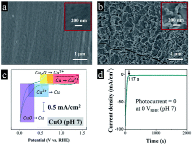
From the SEM images in Fig. 1a, we can see the pre-clean Cu foil exposed a comparatively smooth morphology. After a fast fire treatment, a dense and brunette oxide layer grew on the metal surface. The oxide layer thickness increases as the fire treatment period extends. The average film thickness is 150 nm after 10 s of the fire treatment confirmed by the cross section SEM images, which is much thinner in comparison with the traditional calcination in a muffle furnace.7 The moderate thickness is convenient for the separation of charge carriers, preventing fast recombination.8 The metal interlayer serves to transfer electrons, while the oxide layer is responsible for absorbing photons and generating free electrons. Fig. 1b implies the fast fire treatment caused thermal expansion and contraction, produced a rough and wrinkled oxide layer.
It is a common that acidic electrolytes benefit hydrogen evolution reaction, because of high concentrations of protons.9 In previous studies, most of the colleagues try their best to improve the performance of CuO photocathode in Na2SO4 electrolyte.10,11 However, the cyclic voltammetry in Fig. 1c demonstrates that Cu(2+)O spontaneously corrupts to Cu(0) below 0.3 VRHE (eqn (1)), which is buttressed by our photoelectrochemical test in Fig. 1d, predictably, the CuO photocathode deactivated abruptly in dark (the dark current density reached 93 mA cm−2 at 0 VRHE), and totally no photocurrent can be observed under illumination (the dark current density decayed to a stable value of 0.5 mA cm−2). After the reaction, the brunette absorbing layer disappeared, recovered a shiny metallic luster.
| CuO + 2e− + 2H+ → Cu + H2O, Eθ = +0.3 VRHE | (1) |
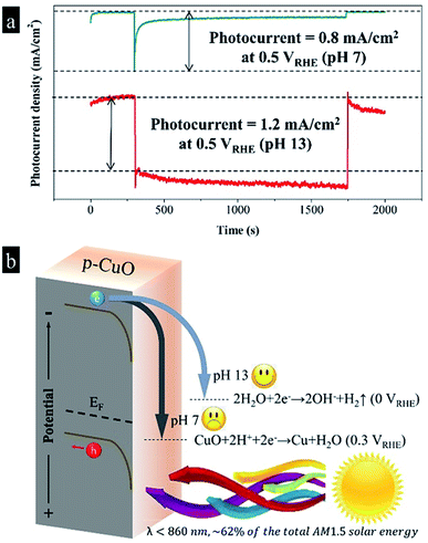
To avoid the fast self-corrosion of the CuO photocathode below 0.3 VRHE, at the same time for the further combination with the photoanodes, we increased the voltage applied to CuO photocathode to 0.5 VRHE, and at this time we found a photocurrent spike of 0.8 mA cm−2 appeared, followed by a continuous decrease to 0.1 mA cm−2 after 1000 s irradiation in Fig. 2a. The result implies that a slow deactivation process still exists, similar to the phenomenon in Jang's work.3 In the retardatory deactivation process, the surface Cu(2+)O is reduced to Cu(0), eqn (1), by the energetic photo-induced electrons. The accumulated Cu layer isolates the inner CuO from the electrolyte, which slows down the current decay. The extreme instability of CuO photocathode forced us to find a new path of using it.
After realizing that CuO is extremely sensitive to protons, which causes fast photo-induced inactivation, we tried to raise the pH value and reduce the proton concentration. Adjusting pH value is often an effective means for changing the course of a chemical reaction.12,13 After substituting NaOH for Na2SO4 in the electrolyte, we discovered that the CuO photocathode produced a photocurrent density of 1.2 mA cm−2 at 0.5 VRHE in pH 13 without any decay during 1000 s. It is meaningful to find adjusting pH value has an ability to alter the selectivity of the CuO photocathode, which seems the easiest way to stabilize the CuO photocathode. As shown in Fig. 2b, according to the previous studies, the Fermi level of CuO is near to 0.8 VRHE, while the calculated band gap is 1.6 eV.3,14 As CuO is a p-type semiconductor, assuming that the energy gap between Fermi level and valence band is 0.3 eV,15,16 the conduction band and valence band are −0.5 VRHE and 1.1 VRHE, respectively. Consequently, in the neutral condition, photo-excited electrons in the conduction band move downward and reduce surface CuO to Cu. As a result, we observed a fast descent of the photocurrent density. As mentioned above, the accumulated Cu layer isolates the inner CuO from the electrolyte, which slows down the current decay. Comparatively, photo-induced electrons selectively reduce water into hydrogen in the basic environment, while the deactivation reaction is somewhat neglected. The least of perfection, in the basic solution the good stability was accompanied by a slow recovery of the dark current.4
| CuO + H2O + 2e− → Cu + 2OH−, Eθ = +0.3 VRHE | (2) |
After tuning the light intensity from 100 mW cm−2 to 20 mW cm−2, it is really interesting to find the relaxation of dark current disappeared, although the photocurrent density decreased to 0.3 mA cm−2. It is not difficult to associate this relationship with the shift of Fermi level. We interpret the mechanism in Fig. 3, under the powerful beam, the Fermi level transfers to the potential that is higher than the Eθ(Cu/CuO), in this case, the photo-excited electrons partially reduce surface CuO to Cu (eqn (2)), followed by generating Cu(OH)2 spontaneously (eqn (3)). Cu(OH)2 is a weak p-type semiconductor, leading to the relaxation phenomenon. Oppositely, the Fermi level stays below the Eθ(Cu/CuO) under low light intensity, which inspires the photo-electrons to fulfill the water reduction. Consequently, CuO photocathode shows a satisfactory photo-stability at 0.5 VRHE with 100% retention of the photocurrent density after 20 min.
| Cu + 2OH− + 2h+ → Cu(OH)2, Eθ = −0.2 VRHE | (3) |
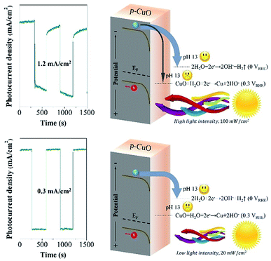 | ||
| Fig. 3 The comparison of the mechanism at pH 13 under high light intensity (100 mW cm−2) and low light intensity (20 mW cm−2). | ||
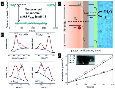
As known to all, the power of sunlight varies with time in real life, it is really difficult to limit the maximum value from 100 mW cm−2 to 20 mW cm−2. Afterwards, we designed a triple-component protective layer of TiO2/La2O3/NiO to neutralize the disadvantage, the thicknesses of TiO2, La2O3 and NiO were 50 nm, 100 nm and 18 nm, respectively. The different film thicknesses were obtained by controlling the dip-coating processes (ESI†). The multilayer structure not only controls the light intensity within an appropriate range but also has a catalytic influence. The TiO2 wrapped the CuO surface and reduced the surface roughness in Fig. 4a, while the subsequent La2O3/NiO totally covered the substrate, making the surface smooth under the electron microscope (Fig. 4b). The optimized CuO photocathode (Fig. 4c) produced a thoroughly stable photocurrent density of 0.3 mA cm−2 at 0.5 VRHE under AM 1.5 G condition for 20 min, meanwhile, the dark current density recovers quickly and keeps steady, shown in Fig. 5a.
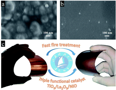 | ||
| Fig. 4 The surface SEM images of (a) the CuO/TiO2 and (b) the CuO/TiO2/La2O3/NiO; (c) schematic plot of the preparation of the CuO/TiO2/La2O3/NiO photocathode. | ||
The high stability of around 100% is found to be the highest reported value in terms of a plain CuO photocathode (Table 1). To certify the fundamental chemical stability, X-ray photoelectron spectroscopy (XPS) was applied to detect the surface properties and oxidation states, shown in Fig. 5b. X-ray induced Auger electron spectroscopy (XAES) was employed in the Cu LMM region to get information of the oxidation state of Cu (Fig. 5b), as the Cu 2p binding energies are almost indistinguishable. The Cu LMM peak at 917.7 eV was assigned to Cu2+. The binding energies of Ti 2p3/2, La 3d5/2 and Ni 2p3/2 were 458.7, 834.5 and 835.7 eV, respectively, corresponding to Ti(4+), La(3+) and Ni(2+). Furthermore, the XPS spectra before and after reactions in Fig. S1† indicate the metal oxidation states in Cu(2+)O, Ti(4+)O2, La(3+)2O3 and Ni(2+)O did not change after 30 min reaction, which met our expectations. Moreover, the construction of this multi-layer photocathode is depicted in Fig. 5c. Many researchers predicted that the conduction band position of CuO is not negative enough to drive the hydrogen evolution reaction. In fact, we found CuO possesses a conduction band edge near to −0.5 VRHE, which means the photoelectrocatalytic hydrogen evolution from water by CuO should be thermodynamically favorable. In the present work, the photo-induced electrons in p-CuO were driven by the depletion layer (p-CuO/n-TiO2 p–n junction) to n-TiO2, then penetrated the La2O3 layer. Herein, La2O3 can be considered as a proton insulating layer.17 After hundreds of attempts, we found that La2O3 is one of the materials that effective for the stabilization of copper oxide, and the stability enhanced with the increasing thickness, until a thickness of 100 nm can balance the stability and the activity. Although La2O3 has a large theoretical band gap (3.8–5.8 eV), it contains deep levels and trap-states, which reduce the band gap (2.9 eV, fluorescence emission at 416 nm) and the resistivity (∼10 kΩ cm).18–20 The deep levels and trap-states form intermediate levels in the large band gap, facilitating the charge transportation. Thus, La2O3 accepts the photo-induced electrons from TiO2 and allow them to pass through. Finally, the electrons enter a second depletion layer, as p-NiO equilibrates with the electrolyte, and complete the water reduction. By the way, we have to mention that TiO2, La2O3 and NiO perform their respective duties and are indispensable. The amounts of H2 and O2 that evolved were determined by gas chromatography. In Fig. 5d, the theoretical amounts of gases expected from photocurrent generations are compared with the actual generation of the gases. The difference between these two values is represented by the faradaic efficiency. The faradaic efficiency of the hydrogen evolution was determined to be 94% when the system was stabilized and showed a steady state. The rest 6% could be accounted for the inefficient gas collection (gas dissolution and strong adsorption on the electrode surface) and some parasitic electrochemical processes.
| Electrolyte | Light intensity (mW cm−2) | Bias (VRHE) | Constructure | Stability | Ref. |
|---|---|---|---|---|---|
| 0.25 M Na2SO4 | 109 | 0 | ZnO/CuO | 40% (3 min) | 21 |
| 1 M NaOH | 100 | 0.25 | CuO | 40% (20 min) | 22 |
| 0.5 M Na2SO4 | 100 | 0.2 | CuO | 80% (15 min) | 3 |
| 0.25 M Na2SO4 | 100 | 0.2 | ZnO/CuO | 90% (6 min) | 23 |
| 0.5 M Na2SO4 | 100 | 0 | Au–Pd/CuO | 90% (20 min) | 24 |
| 0.1 M Na2SO4 | 100 | 0.2 | CuO | 70% (15 min) | 25 |
| 0.1 M Na2SO4 | 100 | 0.05 | CuO | 90% (5 min) | 10 |
| 1 M NaOH | 100 | 0.5 | CuO | ∼100% (20 min) | Present work |
Conclusions
Cupric oxide is not chemically inert in aqueous solution under illumination because of its sensitivity to protons, which makes a painstaking process of fabricating stable CuO photocathodes. It is found the photo-stability of CuO photocathode is highly dependent on the pH value, working potential, light intensity and protective overlayer. After optimization, we applied CuO photocathode in basic environment coupled with a multifunctional semiconductor overlayer, i.e. TiO2/La2O3/NiO, in which p-CuO/n-TiO2 forms a p–n junction, accelerating the charge separation, while La2O3 and NiO act as a proton-isolating layer and a catalyst layer, respectively. The photocurrent density is 0.3 mA cm−2 at 0.5 VRHE with 100% retention after 20 min, as well as the dark current density.Conflicts of interest
There are no conflicts to declare.Acknowledgements
This work has been supported by National Nature Science Foundation of China (No. 21606171), China Postdoctoral Science Foundation (No. 2015M580205 and 2017T100160), and Tianjin University Independent Innovation Foundation (1705).Notes and references
- M. G. Walter, E. L. Warren, J. R. McKone, S. W. Boettcher, Q. Mi, E. A. Santori and N. S. Lewis, Chem. Rev., 2010, 110, 6446–6473 CrossRef CAS PubMed.
- K. Sivula, Chimia, 2013, 67, 155–161 CrossRef CAS PubMed.
- Y. J. Jang, J. W. Jang, S. H. Choi, J. Y. Kim, J. H. Kim, D. H. Youn, W. Y. Kim, S. Han and J. Sung Lee, Nanoscale, 2015, 7, 7624–7631 RSC.
- X. B. Chen, S. H. Shen, L. J. Guo and S. S. Mao, Chem. Rev., 2010, 110, 6503–6570 CrossRef CAS PubMed.
- Y. Li and H. Chen, J. Mater. Chem. A, 2016, 4, 14974–14977 RSC.
- Y. Li, N. Guijarro, X. Zhang, M. S. Prevot, X. A. Jeanbourquin, K. Sivula and H. Chen, ACS Appl. Mater. Interfaces, 2015, 7, 16999–17007 CrossRef CAS PubMed.
- Y. Li, X. Zhang, H. Chen and Y. Li, Catal. Commun., 2015, 66, 1–5 CrossRef CAS.
- Y. Li, Z. Yu, J. Meng and Y. Li, Int. J. Hydrogen Energy, 2013, 38, 3898–3904 CrossRef CAS.
- S. Trasatti, J. Electroanal. Chem. Interfacial Electrochem., 1972, 39, 163–184 CrossRef CAS.
- Y. F. Lim, C. S. Chua, C. J. Lee and D. Chi, Phys. Chem. Chem. Phys., 2014, 16, 25928–25934 RSC.
- Z. Yu, J. Meng, Y. Li and Y. Li, Int. J. Hydrogen Energy, 2013, 38, 16649–16655 CrossRef CAS.
- S. Štrbac and R. R. Adžić, Electrochim. Acta, 1996, 41, 2903–2908 CrossRef.
- S. Yasutomi, T. Morita and S. Kimura, J. Am. Chem. Soc., 2005, 127, 14564–14565 CrossRef CAS PubMed.
- Q. Huang, F. Kang, H. Liu, Q. Li and X. Xiao, J. Mater. Chem. A, 2013, 1, 2418–2425 RSC.
- Y. Matsumoto, J. Solid State Chem., 1996, 126, 227–234 CrossRef CAS.
- Y. Li, X. Zhang, S. Jiang and Y. Li, J. Catal., 2014, 320, 208–214 CrossRef CAS.
- D. Bae, B. Seger, P. C. K. Vesborg, O. Hansen and I. Chorkendorff, Chem. Soc. Rev., 2017, 46, 1933–1954 RSC.
- G. Shang, P. W. Peacock and J. Robertson, Appl. Phys. Lett., 2004, 84, 106–108 CrossRef CAS.
- C. G. Hu, H. Liu, W. T. Dong, Y. Y. Zhang, G. Bao, C. S. Lao and Z. L. Wang, Adv. Mater., 2007, 19, 470–474 CrossRef CAS.
- S. S. Kale, K. R. Jadhav, P. S. Patil, T. P. Gujar and C. D. Lokhande, Mater. Lett., 2005, 59, 3007–3009 CrossRef CAS.
- A. Kargar, Y. Jing, S. J. Kim, C. T. Riley, X. Pan and D. Wang, ACS Nano, 2013, 7, 11112–11120 CrossRef CAS PubMed.
- M. Patel, R. Pati, P. Marathey, J. Kim, I. Mukhopadhyay and A. Ray, J. Electrochem. Soc., 2016, 163, H1195–H1203 CrossRef CAS.
- F. Wu, F. Cao, Q. Liu, H. Lu and L. Li, Sci. China Mater., 2016, 59, 825–832 CrossRef CAS.
- S. Masudy-Panah, R. Siavash Moakhar, C. S. Chua, A. Kushwaha and G. K. Dalapati, ACS Appl. Mater. Interfaces, 2017, 9, 27596–27606 CrossRef CAS PubMed.
- J. Han, X. Zong, X. Zhou and C. Li, RSC Adv., 2015, 5, 10790–10794 RSC.
Footnote |
| † Electronic supplementary information (ESI) available. See DOI: 10.1039/c9ra00865a |
| This journal is © The Royal Society of Chemistry 2019 |

