 Open Access Article
Sacrificial carbonaceous coating over alumina supported Ni–MoS2 catalyst for hydrodesulfurization†
Yingrui Xua,
Pengyun Lia,
Shenghua Yuanb,
Baokuan Suib,
Weikun Lai *a,
Xiaodong Yi
 *a and
Weiping Fanga
aNational Engineering Laboratory for Green Chemical Productions of Alcohols-Ethers-Esters, College of Chemistry and Chemical Engineering, Xiamen University, Xiamen 361005, China. E-mail: xdyi@xmu.edu.cn; laiweikun@xmu.edu.cn
bSINOPEC Dallian Research Institute of Petroleum and Petrochemicals, Dalian 116045, China
First published on 16th April 2019
Abstract
Recent results have evidenced that carbon plays an important role in stabilizing the structure of the active phase in catalysts. In this work, carbon-coated alumina was prepared by applying polydopamine (PDA) as a sacrificial carbon source to modify the surface properties of γ-alumina, which then was used as a support to prepare supported NiMo catalysts for hydrodesulfurization (HDS) of dibenzothiophene (DBT). NiMo/Al2O3 catalysts exhibited limited hydrodesulfurization performances due to their strong metal-support interaction. Herein, we report an unexpected phenomenon that sacrificial carbon layers can be constructed on the surface of the Al2O3 support from the carbonization of polydopamine (PDA) and mediated the interaction between the active site and support. Through the removal of carbon layers and sulfidation, the resulting NiMo catalysts exhibit excellent performance for HDS reaction of dibenzothiophene (DBT), which is associated with adequate loading of residual carbon species, leading to an enhanced amount of active species under sulfidation conditions. Moreover, the facile synthetic strategy can be extended to the stabilization of the active phase on a broad range of supports, providing a general approach for improving the metal-support interaction supported nanocatalysts.
Introduction
The hydrotreating processes (HDT) has been one of the most important processes in petroleum industry due to the increasing demand for high-quality ultra-clean fuel production from heavy crude oils and the stringent regulations on environmental issues. Among all the contaminants in gasoline or diesel oil, sulfur-containing compounds such as thiophene, benzothiophene (BT), dibenzothiophenes (DBT), and dimethyldibenzothiophenes (DMDBT), which generate SOX gases, must be degraded or removed in order to prevent air pollution. Despite development of techniques such as adsorption oxidative desulfurization, adsorptive desulfurization and biodesulfurization, catalytic hydrodesulfurization has been proved as the most effective method for industrial application.1–4Over the past decades, the traditional HDS catalysts consisted of Ni (Co)–Mo (W) pre-sulfided to form metal sulfide (WS2 or MoS2,main component) coexisting with promoters (Ni or Co) loading on the oxide support with high surface area.5–7 Considering its tunable and stable mechanical characteristics and low cost, alumina has been the most commonly applied support for HDS.8–10 However, the conventional alumina interact strongly with metal oxide precursors to form species that are hard to be reduced or sulfided.11–13
Towards this, various new support materials are introduced for HDS catalysts. Those carbon-based materials, such as active carbon or graphene with hierarchical structures and high surface area, seem to be promising support materials in hydrotreating reactions of heavy crude oil.10,14,15 The varied functional groups on the carbon materials could be tailored by oxidizing agents during the preparing process, which is very different from the surface chemistry of alumina.16–19 As a consequence, catalysts prepared with carbon as support (active carbon or graphene) were more active than their alumina-supported counterparts.20–22 However, the significant disadvantage of carbon supports for low packing density limits their application in commercial HDT catalyst formulations.23
As the dispersion of the catalytic metal-sulfide is difficult to enhance due to the strong polarity and the limited surface area of the alumina support,10,24–26 modification of alumina surfaces to acquire proper acidic properties or appropriate metal-support interactions were frequently applied in preparing HDS catalysts with higher activity. In some other cases, interactions between the loaded metal and support (carbon materials) may cause serious sintering problems under reaction conditions.17 In order to properly alter the interaction between active component and supporting material, alumina supported systems with carbon11,27 were found to be more preferred to apply in certain reaction systems. Thus the surface chemistry of carbon-based materials, which might be tailored by oxidizing agents and eventually affect the active phase on the catalyst, has been investigated by many authors.16,17,19 Thus the conception of adding carbon in tailoring surface of alumina as support seems an appealing practice in HDS catalysts.
Previous study found polydopamine (PDA) film was able to develop over a wide variety types of material surfaces of complex shape via spontaneous oxidative self-polymerization of dopamine in aqueous solution.26,28 On account of the versatile coating strategy, dopamine exhibits expansive potential as building block for manipulating the coating layers over the support materials. In this work, the surface properties of commercial alumina were tuned by carbon-layers made from pre-loaded polydopamine. The accumulation of PDA layer could effectively promote the reduction and sulfidation degree of subsequently loaded active phase. The polydopamine layers tend to form thin shells over the alumina surface, creating a complete interval between active phase and support to avoid strong interactions. Meanwhile, the carbon shell was easily removed by post-thermal treatment under flowing air, leaving the well-established metal-support interfaces undestroyed. As a result, the HDS activity of supported catalyst is positively affected. Consequently, discussions were carried out based on the role of air-annealed carbon coating in affecting the HDS activity trends of NiMo/alumina catalysts.
Experimental sections
Materials
All of these reagents were purchased from Sinopharm Chemical Reagent Co. and were used without further purification, except that the dibenzothiophene (DBT) was purchased from Sigma-Aldrich. In addition, the commercial alumina support used as a control was obtained from Fushun Research Institute of Petroleum and Petrochemicals, SINOPEC, Fushun, China.Preparation of PDA coated γ-alumina support
The tris(hydroxymethyl)methyl aminomethane buffer solution (10 mM) with PDA (x mg mL−1) was adjusted to pH = 8.5 with NaOH. Then the buffer solution with 5 g alumina powder was transferred to a beaker under stirred conditions for 24 h at room temperature. The product was collected and washed twice with deionized water by centrifugation. Then the product was dried at 120 °C overnight to generate Al@PDA-x samples.Preparation of carbon coated γ-alumina support
The carbon-coated supports (denoted as Al@C-1) were prepared with Al@PDA-1 samples subjected to annealing treatment at 500 °C in N2 flow for 2 h at a heating rate of 5 °C min−1.Preparation of HDS catalysts
The HDS catalysts were prepared by loading the active components Ni and Mo on the alumina@carbon supports via simultaneous incipient wetness impregnation method. The Ni and Mo precursors ((NH4)6Mo7O24·24H2O, 0.1168 g and Ni(NO3)2·6H2O, 0.1472 g) were mixed and well dispersed in deionized water. After impregnation over 0.85 g support, the catalyst precursors (NiMoAl@PDA-x and NiMoAl@C-1) were dried at 120 °C overnight and calcined in flowing air at 500 °C for 2 h. The final loading amount is 3.0 wt% of NiO and 12.0 wt% of MoO3 for each catalyst. The catalysts with Ni Mo loading over Al@PDA-x and Al@C-1 were denoted as NiMoAl-x and NiMoAl-1#, respectively. The commercial alumina loaded catalyst was denoted as NiMoAl-0.Characterization
The nitrogen adsorption–desorption measurements of the composite were performed on a Micromeritics Tristar 3020 adsorption automatic instrument at −196 °C. The samples were pretreated at 300 °C for 3 h in vacuum. The specific surface area and pore volume of the catalysts were calculated from nitrogen adsorption–desorption isotherms using the Brunauer–Emmett–Teller (BET) and Barrett–Joyner–Halenda (BJH) methods. Powder X-ray diffraction (XRD) characterization was carried out on a Rigaku Ultima IV automatic powder diffractometer operated at 40 kV and 30 mA using Cu Kα (λ = 0.15406 nm) monochromatized radiation with a scan speed of 10° min−1. The JCPDS file database was used for peak identification. To evaluate the combustion reactions, thermogravimetric analysis (TGA) of the precursor before the combustion occurred was conducted in flowing air up to 800 °C at a heating rate of 10 °C min−1 using a simultaneous TGA (SDT Q600) thermal analyzer. Temperature Programmed Oxidation (TPO) was carried out on a Micromeritics AutoChem II 2920 instrument. The catalysts (100 mg) were pretreated in flowing helium at 400 °C for 1 h before cooled down to 30 °C. Then the sample was subjected to oxidation test from 30 to 800 °C at a rate of 10 °C min−1 in a 5% O2/He stream (20 mL min−1). The temperature programmed reduction (TPR) of the sample was performed over a homemade GC-TPR apparatus. For each test, 50 mg catalyst was pretreated in flowing Ar stream at 300 °C for 1 h and then cooled to 50 °C. Subsequently, a 5% H2/Ar atmosphere was altered and the catalyst sample was heated to 900 °C with a ramping rate of 10 °C min−1. The morphology of the samples was acquired by a Sigma Zeiss scanning electron microscope (SEM) at 5–15 kV. The regular transmission electron microscopy (TEM) images by a JEM-1400 at 100 kV, and high-resolution transmission electron microscopy (HRTEM) images of the samples were obtained using a Jeol JEM-2100F field emission electron microscope operating at 200 kV. After ultrasonically dispersed in ethanol, the testing samples were prepared by dropping the dispersed suspensions onto carbon-coated copper grids.The MoS2 dispersion over the sulfided catalysts was further determined by HRTEM measurement. The average slab length (![[L with combining macron]](https://www.rsc.org/images/entities/i_char_004c_0304.gif) ) and stacking number (
) and stacking number (![[N with combining macron]](https://www.rsc.org/images/entities/i_char_004e_0304.gif) ) were calculated based on the following expressions:
) were calculated based on the following expressions:
 | (1) |
 | (2) |
 | (3) |
Catalytic performance evaluation
The dibenzothiophene hydrodesulfurization activity of the catalysts was evaluated in a high-pressure fixed-bed continuous-flow stainless steel reactor, using 2.0 wt% DBT in cyclohexane as a model compound. For each run, 100 mg catalyst (20–40 mesh particle size), which was diluted with 400 mg quart pellets, was presulfided at 400 °C at a flow rate of 40 mL min−1 of 15% H2S/H2 under atmospheric pressure. The tests were stabilized at 250 °C with a total pressure of 1.5 MPa, a liquid hour space velocity (LHSV) of 4 h−1 and an H2/oil ratio of 600/1 (v/v). The liquid product was collected and analyzed by a gas chromatograph (GC-9560) equipped with FID detector and SE-30 capillary column. The reaction products were identified by matching their retention times with those of the commercial standards together with GC/MS analysis using a Finnigan Trace DSQ.Results and discussion
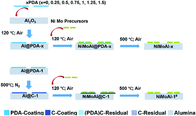
The commercial alumina applied in preparing Al2O3@C materials were small grains with irregular shape. After 24 h of stirring in a Tris buffer solution with dopamine constituent, the alumina was covered by polydopamine assemblies (denoted as Al@PDA-x) without any visible modification in the particle size, underlining the advantage of a dopamine-based synthetic strategy for constructing shell architectures. When subjected to a thermal treatment at 500 °C in N2 atmosphere, the PDA layers were converted in situ to form robust carbon shells (Al@C). The catalysts were prepared by loading Ni and Mo species directly over commercial alumina, Al@PDA-x or Al@C-1 support and then annealed in flowing air. The catalyst precursors before calcination are denoted as NiMoAl@PDA-x and NiMoAl@C-1 (the catalysts NiMoAl-x and NiMoAl-1# were generated from NiMoAl@PDA-x and NiMoAl@C-1), respectively (Scheme 1). TG and TPO technique were used to study the thermal decomposition of the carbon-containing precursors (Ni and Mo species loaded over uncalcined PDA or carbon-coated alumina) with different PDA content and determine the annealing conditions from the calcination procedure of oxide catalysts. Notably, the NiMoAl-0 catalyst shows a slight decrease in mass, which corresponds to the combustion process includes the dihydroxylation of alumina (before 140 °C) and the decomposition of Ni and Mo precursors (140–600 °C). For the Ni and Mo loaded catalysts with PDA precursors, the thermal decomposition can be divided into three regions, which are located in 40–140 °C, 140–400 °C, and 400–700 °C, respectively. As shown in Fig. 1a, the weight loss at 40–140 °C is ascribed to the removal of physical-adsorbed moisture,29 and the abrupt weight loss between 140 and 400 °C during the calcination is attributed to the carbonization of PDA coating and loss of dehydroxylation of alumina30 while process at 400–700 °C to the combustion of carbon29 and Ni–Mo species.30 The decomposition process of PDA continues until the temperature reaches 900 °C. The weight losses in the 140–400 °C, and 400–700 °C region increased with increase of PDA content in the buffer solution, while the NiMoAl@PDA-1 and NiMoAl@C-1 exhibit TG profiles with similar weight losses (Table S1†).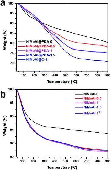 | ||
| Fig. 1 TG curves of (a) the catalysts precursors with carbon content and (b) the corresponding catalysts after annealing under air flow at 500 °C. | ||
To investigate the residual carbon content after calcination in air, the TG patterns of the calcined catalyst were shown in Fig. 1b. The two degradation steps lie in 40–450 °C and 450–700 °C. The weight loss in 40–450 °C were attributable to the removal of physically adsorbed water, the dihydroxylation of alumina and partial decomposition of the residual carbon content. The amount of weight loss in the region of 40–450 °C for the NiMoAl-x catalysts were greater than the NiMoAl-0 sample. The slightly decreased weight in the region of 450–700 °C belongs to the decomposition of coke species which were relatively difficult to degrade. After annealing in flowing air, all the catalysts represent little carbon residuals, which are proved by the results of TG and TPO analysis. This result clearly demonstrates that the dopamine self-assembly strategy affords a good carbon coating on the Al2O3 surface, subsequently underlining the unique structural benefits of the PDA-derived architecture for mediating the surface properties of the support.
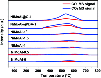
The TPO results in Fig. 2 show that the NiMoAl@C-1 and NiMoAl@PDA-1 samples exhibited the detection of significant CO2 and CO formation by the MS signal (m/z = 44, 28) during the calcination in air, compared with NiMoAl-x catalyst. According to literature, the thermal decomposition of carbon species under air flow could be mainly attributed to the removal of structural carbon at ca. 350 °C and the pyrolysis of support carbon at ca. 550 °C.31 However, no shoulder peak at ca. 350 °C was attributable to the decomposition of structural carbon in the catalysts, indicating no detectable structural carbon species were formed after annealing under air atmosphere. The existence of support carbon was confirmed by the peaks centred at 400–600 °C. The results evidence that pre-coated PDA can generate support carbon that would suppress crystallite growth of active phase, probably owing to the sufficient interaction to efficiently suppress the interactions between active phase and the support. Moreover, with increased PDA content, the decomposition peak of carbon residuals at ca. 550 °C shifted to lower temperature region, and the PDA coating on the alumina surface (NiMoAl@PDA-1) was easier to decompose than carbon coating (NiMoAl@C-1).
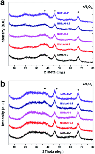
After coated with PDA or carbon coating, γ-alumina was confirmed as the predominant phase without significant phase conversion (Fig. 3). After been calcined under flowing air and subsequently sulfidation, and both of the resulting oxide and sulfide catalysts (NiMoAl-x and NiMoAl-1#) only exhibit XRD patterns with broad diffraction peaks at 45.8° and 66.8°, in accordance with the characteristic patterns of γ-alumina. No diffraction peaks attributed to Ni and Mo phases, such as MoS2, NiSx, NiMoO4, NiAlO4, Al2(MoO4)3, etc., could be observed during any synthetic step, or after sulfidation (Fig. S1†). This observation confirmed the high dispersion of Ni and Mo species over the surface of the supports.
Previous studies show that the deposition kinetics of dopamine does not depend markedly on the surface chemistry of the substrate, and the thickness of films correlate closely to the dopamine content in tris buffer solutions.32 The surface area and porosities of the samples were investigated by N2 adsorption–desorption analysis, and all the samples exhibit similar type IV isotherms with HI hysteresis loops (Fig. S2†). The detailed texture parameters, including the surface areas from BET analysis and the pore volumes from the BJH method are nearly unchanged in reference to the commercial alumina (Table 1), which indicate the addition of PDA coating caused minimum effect on the texture properties of the alumina before and after PDA modification. In contrast, the NiMoAl@PDA-1 and NiMoAl@C-1 catalysts with carbonous shells that were not yet deprived, the surface area and average pore diameter of these two samples were significantly reduced due to the thin film assembly on the surfaces of Al2O3 to reduce accumulated pores by the introduced carbon deposition. These characterizations conclusively demonstrate that the existence of polydopamine-derived carbon. Furthermore, as the deposition kinetics of dopamine does not depend markedly on the surface chemistry of the substrate, which demonstrates the promising strategy for the engineering of supported Ni–Mo nanocatalysts.
| Catalysts | SBETa (m2 g−1) | Vb (cm3 g−1) | Dc (nm) | ![[L with combining macron]](https://www.rsc.org/images/entities/i_char_004c_0304.gif) d (nm) d (nm) |
![[N with combining macron]](https://www.rsc.org/images/entities/i_char_004e_0304.gif) e e |
fMof |
|---|---|---|---|---|---|---|
| a BET surface area.b Pore volume.c Average pore diameter.d Average length of MoS2 nanoslabs.e Average stacking degree of MoS2 nanoslabs.f Average fraction of Mo atoms located on the edge of the MoS2 crystallites. | ||||||
| Al2O3 | 234 | 0.53 | 6.3 | — | — | — |
| NiMoAl-0 | 202 | 0.42 | 6.2 | 5.0 | 2.0 | 0.23 |
| NiMoAl-0.5 | 200 | 0.41 | 6.8 | 4.9 | 2.1 | 0.22 |
| NiMoAl-0.75 | 195 | 0.42 | 6.4 | 4.6 | 2.2 | 0.26 |
| NiMoAl-1 | 192 | 0.40 | 6.4 | 4.8 | 2.1 | 0.25 |
| NiMoAl-1.25 | 190 | 0.39 | 6.7 | 4.9 | 2.0 | 0.23 |
| NiMoAl-1.5 | 187 | 0.40 | 6.8 | 5.0 | 2.2 | 0.22 |
| NiMoAl-1# | 203 | 0.39 | 6.1 | 5.2 | 2.1 | 0.23 |
| NiMoAl@PDA-1 | 157 | 0.33 | 6.0 | — | — | — |
| NiMoAl@C-1 | 161 | 0.35 | 6.5 | — | — | — |
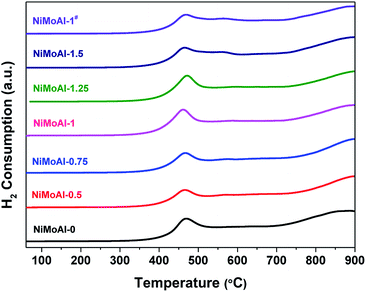
The carbon modified alumina surface have shown valid effect in tailoring the interactions between active phases and support. Thus, temperature programmed reduction (TPR) of the catalysts in oxidic state were carried out to study the reducibility of metallic species loaded on the supports. As expected, the catalysts prepared with carbon-coated alumina were more easily reduced than the NiMoAl-0 under H2 flow according to the corresponding TPR results (Fig. 4). All the catalysts exhibit a principle reduction peak between 400 and 500 °C, which is related to the reduction of octahedral coordinated polymeric Mo species (from Mo6+ to Mo4+).7 This reduction peak for all the catalysts prepared with PDA coating or carbon coating shifted to lower temperature region, meaning that the pre-loaded PDA or carbon shell is capable in weakening the interaction between Mo species and alumina support. When the PDA content in buffer solution increased reaches to 1 mg mL−1 (NiMoAl-1), the first reduction peak of the catalyst located at ca. 450 °C, which is lowest among all the catalysts. The peak position for NiMoAl-1# was similar with NiMoAl-1, which was also located at lower temperature region than the commercial catalyst. The weak shoulder peak at 500–600 °C, which could be attributed to reduction of NiO, increased with increasing PDA content, indicating the addition of PDA attribute to the dispersion of NiO over the surface of alumina. The reduction peak located at 700–900 °C is related to a further reduction of Mo4+ to Mo0. In contrast, without PDA introduced, the NiMoAl-0 catalysts show strong high-temperature Mo reduction peaks, resulting in strong metal-support interaction and diminished catalytic performance. The result provided that the modified interaction between the carbon and support, or improved the thermal stability of active phases were retained after a 500 °C annealing in air, which were similar with the result in previous study.33
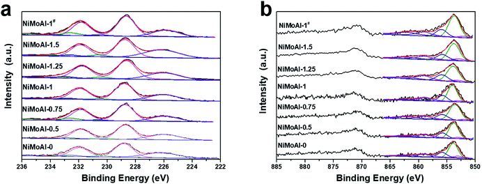
The XPS spectra of the sulfided catalysts were collected and then decomposed in order to characterize the bonding state and surface concentration of the active phase over the catalyst. While no evidence in C 1s (Fig. S3†) shows proof for the formation of NiMoC phase, it is well admitted that the sulfidation degree of Mo and the formation of NiMoS phase are considered to be vital on determining their HDS performance.6 Therefore, the deconvolution results of Mo 3d and Ni 2p spectra were well collected in Table 2. According previous studies, the binding energy of located at 228.7 ± 0.1 eV, 232.6 ± 0.2 eV and 230.6 ± 0.2 eV were well attributed to the disulfide phase or MoS2 (MoIV 3d5/2), the Mo oxide species (MoVId5/2) and an intermediate phase (MoV 3d5/2, which can be identified as MoOxSy species), respectively. The broad peak centred at ca. 226.0 eV is assigned to the S 2s, which should be subtracted from the total spectrum of Mo 3d.19,34 Compared with the catalysts prepared with PDA, the decreased amount of MoVI and MoV species of NiMoAl-0 shown in Table 3 can be indicating the existence of Mo species that were difficult to reduced, which can be ascribed to the strong interaction between active phase and alumina support. The atomic fractions of MoS2 for the PDA or carbon- modified catalyst are higher than the commercial catalyst, while the NiMoAl-1 sample exhibit largest MoS2 constitution, which demonstrated the highest sulfidation degree.
| Catalysts | MoIV | MoV | MoVI | NiMoS | NiSx | NiII | ||||||
|---|---|---|---|---|---|---|---|---|---|---|---|---|
| BE (eV) | % atom | BE (eV) | % atom | BE (eV) | % atom | BE (eV) | % atom | BE (eV) | % atom | BE (eV) | % atom | |
| NiMoAl-0 | 228.8 | 80.5 | 230.4 | 7.9 | 232.7 | 11.6 | 853.7 | 65.0 | 853.1 | 4.5 | 856.0 | 30.5 |
| NiMoAl-0.5 | 228.7 | 82.2 | 230.4 | 8.5 | 232.6 | 9.3 | 853.8 | 68.8 | 853.0 | 7.2 | 856.2 | 24.0 |
| NiMoAl-0.75 | 228.7 | 83.0 | 230.6 | 5.2 | 232.6 | 11.8 | 853.6 | 71.4 | 853.1 | 4.2 | 856.1 | 24.4 |
| NiMoAl-1 | 228.7 | 84.2 | 230.4 | 7.3 | 232.8 | 8.5 | 853.7 | 69.6 | 853.0 | 5.4 | 856.1 | 25.0 |
| NiMoAl-1.25 | 228.6 | 82.7 | 230.5 | 7.5 | 232.8 | 9.8 | 883.7 | 67.1 | 853.0 | 6.2 | 856.2 | 26.7 |
| NiMoAl-1.5 | 228.7 | 82.4 | 230.6 | 8.5 | 232.6 | 9.1 | 853.7 | 64.9 | 853.0 | 7.5 | 856.2 | 26.6 |
| NiMoAl-1# | 228.7 | 82.5 | 230.6 | 6.2 | 232.6 | 11.3 | 853.6 | 70.6 | 853.0 | 5.2 | 856.2 | 24.2 |
| Catalyst | Product distributionb (%) | DBT | Rc | ||
|---|---|---|---|---|---|
| BCH | CHB | BP | Conv. (%) | (10−7 mol g−1 s−1) | |
| a Reaction conditions: temperature 300 °C, H2 pressure 2.0 MPa, LHSV 12 h−1, H2/liquid (v/v) 600, feed 2 wt% DBT in decalin.b BCH: bicyclohexyl, CHB: cyclohexylbenzene, BP: biphenyl, DBT: dibenzothiophene.c Average specific rate (moles of DBT transformed per second and per gram of catalyst). | |||||
| NiMoAl-0 | 1.8 | 10.2 | 88.0 | 74.2 | 5.8 |
| NiMoAl-0.5 | 2.0 | 14.6 | 83.4 | 79.3 | 6.2 |
| NiMoAl-0.75 | 1.8 | 14.8 | 83.4 | 78.9 | 6.1 |
| NiMoAl-1 | 1.6 | 10.4 | 88.0 | 88.5 | 6.9 |
| NiMoAl-1.25 | 1.8 | 10.1 | 88.1 | 82.4 | 6.4 |
| NiMoAl-1.5 | 1.9 | 12.0 | 86.1 | 83.7 | 6.5 |
| NiMoAl-1# | 2.2 | 13.5 | 84.3 | 85.3 | 6.6 |
As shown in Fig. 5b, Ni species in the sulfided catalysts can be divided into three categories: the NiMoS phase located at 853.7 ± 0.2 eV, the NiSx species located at 853.0 ± 0.1 eV and the unsulfided NiO species centered at 856 ± 0.2 eV. The remaining two broad peaks are satellite lines of the corresponding Ni species as a supplement. The fraction of NiMoS phase for all the NiMoAl-x is higher than the commercial catalyst (NiMoAl-0), while the NiMoAl-1 exhibit highest NiMoS proportion, indicating that this catalyst possessed the largest number of active sites, which were in good accordance with the results of atomic fraction for MoIV phase. The relative higher fraction of NiMoS phase demonstrated that the interaction between active phases and support alumina were significantly reduced, resulting in catalysts with better sulfidation degree, which could lead to promoted catalytic HDS performance. As expected, the active phases over carbon-coated alumina annealing in flowing air atmosphere (NiMoAl-1#) exhibited enhanced NiMoS phase fractions than the unmodified NiMoAl-0, which indicate that the carbon layers were also efficient in optimising the interaction between active phases and support, yet is slight inferior to the PDA-coating (NiMoAl-1).
High resolution transmission electron microscopy (HRTEM) was carried out to further observe the morphology and structure of the catalysts in sulfided state. The randomly oriented MoS2 layers with a lattice distance for the (002) plane of ca. 0.61 nm could be observed in all the HRTEM images (Fig. 6 and S3†). The MoS2 dispersion over the sulfided catalysts was also determined by HRTEM measurement, and the statistic results were summarized in Table 1. Compared with the commercial catalyst, the NiMoAl-x catalysts exhibit slightly larger stacking number (Ns) of MoS2 (Ls = 4.8–5.2 nm, Ns = 1.9–2.2, Table 1). Specially, the NiMoAl-1 sample exhibits an adequate Ls value of 4.6 nm with the largest stacking number of 2.2. Therefore, the NiMoAl-1 sample presents the highest calculated dispersion among the relevant catalysts. That is, it possessed the largest population of active edge sites among all the catalysts, indicating the effect of residual carbon species over the dispersion of active phases. Thus the occupation of Ni atoms on the edge sites of MoS2 can be efficiently promoted, which favor the formation of Ni–Mo–S active phases.34 This result clearly demonstrates that the high MoS2 dispersion was obtained by the strategy of thermally annealing Al2O3 enclosed within polydopamine formed carbon shells with NiMo precursor, which would influence the catalytic performance of the NiMo catalyst in HDS reactions.
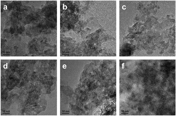 | ||
| Fig. 6 Typical HRTEM images of the sulfided (a) NiMoAl-0 (b) NiMoAl-0.5 (c) NiMoAl-0.75 (d) NiMoAl-1 (e) NiMoAl-1.25 (f) NiMoAl-1.5. | ||
The as-prepared catalysts were tested to evaluate their hydrodesulfurization (HDS) performance, and the bulk sulfur-containing molecular, dibenzothiophene (DBT) was selected as model compound to evaluate the HDS performance of the PDA-modified catalysts, in comparison with the commercial catalysts (NiMoAl-0). The catalytic activities of the as-prepared catalysts were evaluated under 300 °C with an H2/liquid of 600/1 (v/v), a liquid hour space velocity (LHSV) of 12 h−1 and a total pressure of 2.0 MPa. The conversion and detailed product selectivity were listed in Table 3. Previous studies proved that the HDS reactions of DBT also occurs in two parallel paths: the direct desulfurization pathway (DDS pathway), where biphenyl (BP) was produced; and the hydrogenation route (HYD pathway), where the cyclohexylbenzene (CBH) and dicyclohexyl (DCH) were formed (Scheme S1†). As displayed in Table 3, all the NiMoAl-x series catalysts exhibit higher HDS activity of DBT under such reaction conditions. The HDS catalytic efficiencies towards DBT over NiMoAl-x catalysts increased with increasing PDA content and peaked at approximately 1 (x value in NiMoAl-x). However, further increasing the PDA content demonstrated no positive changes in the catalytic efficiency. The result indicates that after annealing in flowing air at 500 °C for combustion of the carbon shells, the HDS activity over the PDA or carbon coating catalysts were promoted compared with the commercial catalyst (NiMoAl-0), which clearly demonstrated the unique structural benefits of the dopamine-derived shell architecture for optimizing the interaction between active phase and alumina support. In this respect, the strategy of thermally annealing Ni Mo catalysts over carbon shells generated from polydopamine was successful in optimizing the properties and activities over NiMo/Al2O3 catalysts. The difference in product distribution for the catalysts were hardly observed as similar active phase were presented, indicating the loading of carbon-residual coating caused minimum effect over the texture properties and the structure of active phase. Interestingly, the MoNiAl-1# catalyst with removed carbon-coating also exhibits promoted DBT conversion than the commercial catalyst, but was slightly lower than MoNiAl-1, which could be probably attributed to a weak metal-support interaction and low specific surface area.17 It is generally known that the catalytic behavior essentially is determined by their structural features and chemical properties. First of all, the maintained surface area of the after removal of carbonous shell contribute to better dispersion of active components, which forms optimized active phases over the catalysts. And the modified surface with adequate amount of carbon, which efficiently weakens the metal-support interaction, also determines the generation of active phases. As discussed in the previous sections, the carbon residual modified alumina enables a higher dispersion of active phases, and more easily reducible components contributing to higher amount of NiMoS phase (Table 2), and further favors fast conversion kinetics over the catalysts. However, the activity decreases with a further increase in the addition of PDA, which should be due to the reduced surface area and decreased population of active phases and the lower MoS2 dispersion.
Conclusions
A general synthetic strategy aimed at mediating Ni–Mo active site with Al2O3 support was successfully developed. Through the surface modification by the sacrificial carbon coating derived from PDA and removal of carbon layers by thermal treatment, NiMoAl-0 catalysts that are efficient for HDS activity of DBT can be obtained. This proper interaction between active phases and the support induced the generation of more easily reducible Ni–Mo species, which can obtain efficiently distributed active site and obtained higher MoS2 dispersion even after removal of the carbon shells. Hence, the HDS catalytic activity was enhanced over a dopamine-mediated catalyst. However, excessive carbon coating exerted a negative effect on the activity supported Ni Mo catalysts. Nevertheless, the properly deposited carbon layers derived from PDA pyrolysis could also contributes to the upgrading of commercial HDS catalysts when applied as sacrificial carbon coating. The findings afford a new avenue for the design and synthesis of other efficient supported catalysts through metal-support interaction tuning.Conflicts of interest
There are no conflicts to declare.Acknowledgements
This work is supported by the National Natural Science Foundation of China (21773194, 21703179, 21473143 and 21373168), and the Fundamental Research Funds for the Central Universities of China (20720170103).Notes and references
- S. A. Al-Hammadi, A. M. Al-Amer and T. A. Saleh, Chem. Eng. J., 2018, 345, 242–251 CrossRef CAS.
- D. Gulková, Y. Yoshimura and Z. Vít, Appl. Catal., B, 2009, 87, 171–180 CrossRef.
- W. Huamin and I. Enrique, ChemCatChem, 2011, 3, 1166–1175 CrossRef.
- A. Niquille-Röthlisberger and R. Prins, J. Catal., 2006, 242, 207–216 CrossRef.
- Y. Okamoto, M. Breysse, G. Murali Dhar and C. Song, Catal. Today, 2003, 86, 1–3 CrossRef CAS.
- Y. Dong, Y. Xu, Y. Zhang, X. Lian, X. Yi, Y. Zhou and W. Fang, Appl. Catal., A, 2018, 559, 30–39 CrossRef CAS.
- Y. Dong, X. Yu, Y. Zhou, Y. Xu, X. Lian, X. Yi and W. Fang, Catal. Sci. Technol., 2018, 8, 1892–1904 RSC.
- P. Rayo, P. Torres-Mancera, G. Centeno, F. Alonso, J. A. D. Muñoz and J. Ancheyta, Fuel, 2019, 239, 1293–1303 CrossRef CAS.
- Y. Villasana, F. J. Méndez, M. Luis-Luis and J. L. Brito, Fuel, 2019, 235, 577–588 CrossRef CAS.
- J. Escobar, M. C. Barrera, A. W. Gutiérrez, M. A. Cortés-Jacome, C. Angeles-Chávez, J. A. Toledo and D. A. Solís-Casados, Appl. Catal., B, 2018, 237, 708–720 CrossRef CAS.
- P. A. Nikulshin, P. P. Minaev, A. V. Mozhaev, K. I. Maslakov, M. S. Kulikova and A. A. Pimerzin, Appl. Catal., B, 2015, 176–177, 374–384 CrossRef CAS.
- R. Obeso-Estrella, J. L. G. Fierro, J. N. D. de León, S. Fuentes, G. Alonso-Nuñez, E. Lugo-Medina, B. Pawelec and T. A. Zepeda, Fuel, 2018, 233, 644–657 CrossRef CAS.
- L. Lv, Y. Bo, D. Ji, W. Han, H. Liu, X. Gao, C. Xu and H. Liu, Ind. Eng. Chem. Res., 2018, 57, 13889–13894 CrossRef CAS.
- B. Wang, C. Xiao, P. Li, Z. Zhao, C. Xu, Z. Zhao, Q. Meng, J. Li, A. Duan and Z. Chen, Ind. Eng. Chem. Res., 2018, 57, 11868–11882 CrossRef CAS.
- W. Zhou, Y. Zhang, X. Tao, Y. Zhou, Q. Wei and S. Ding, Fuel, 2018, 228, 152–163 CrossRef CAS.
- P. Gheek, S. Suppan, J. Trawczyński, A. Hynaux, C. Sayag and G. Djega-Mariadssou, Catal. Today, 2007, 119, 19–22 CrossRef CAS.
- J. Oh, T. W. Kim, K. Jeong, J. H. Park and Y. W. Suh, Chemcatchem, 2018, 10, 3892–3900 CrossRef CAS.
- L. Yang, X. Wang, Y. Liu, Z. Yu, R. Li and J. Qiu, Catal. Sci. Technol., 2017, 7, 693–702 RSC.
- Z. Zhang, X. Jiang, J. Hu, C. Yue and J. Zhang, Catal. Lett., 2017, 147, 2515–2522 CrossRef CAS.
- F. Severino, J. Laine and A. López-Agudo, J. Catal., 2000, 189, 244–246 CrossRef CAS.
- H. Farag, I. Mochida and K. Sakanishi, Appl. Catal., A, 2000, 194–195, 147–157 CrossRef CAS.
- J. Whelan, M. S. Katsiotis, S. Stephen, G. E. Luckachan, A. Tharalekshmy, N. D. Banu, J.-C. Idrobo, S. T. Pantelides, R. V. Vladea, I. Banu and S. M. Alhassan, Energy Fuels, 2018, 32, 7820–7826 CrossRef CAS.
- P. A. Nikulshin, V. A. Salnikov, A. V. Mozhaev, P. P. Minaev, V. M. Kogan and A. A. Pimerzin, J. Catal., 2014, 309, 386–396 CrossRef CAS.
- P. Arnoldy, E. M. Van Oers, V. H. J. De Beer, J. A. Moulijn and R. Prins, Appl. Catal., 1989, 48, 241–252 CrossRef CAS.
- Y. Fan, H. Xiao, G. Shi, H. Liu, Y. Qian, T. Wang, G. Gong and X. Bao, J. Catal., 2011, 279, 27–35 CrossRef CAS.
- G. Mondin, M. Haft, F. M. Wisser, A. Leifert, N. Mohamed-Noriega, S. Dörfler, S. Hampel, J. Grothe and S. Kaskel, Mater. Chem. Phys., 2014, 148, 624–630 CrossRef CAS.
- E. Puello-Polo, A. Gutiérrez-Alejandre, G. González and J. L. Brito, Catal. Lett., 2010, 135, 212–218 CrossRef CAS.
- H. Lee, S. M. Dellatore, W. M. Miller and P. B. Messersmith, Science, 2007, 318, 426–430 CrossRef CAS PubMed.
- W. Lai, W. Song, L. Pang, Z. Wu, N. Zheng, J. Li, J. Zheng, X. Yi and W. Fang, J. Catal., 2013, 303, 80–91 CrossRef CAS.
- M. A. A. Elmasry, A. Gaber and E. M. H. Khater, J. Therm. Anal. Calorim., 1998, 52, 489–495 CrossRef CAS.
- G. Berhault, A. Mehta, A. C. Pavel, J. Yang, L. Rendon, M. J. Yácaman, L. C. Araiza, A. D. Moller and R. R. Chianelli, J. Catal., 2001, 198, 9–19 CrossRef CAS.
- F. Bernsmann, V. Ball, F. Addiego, A. Ponche, M. Michel, J. J. d. A. Gracio, V. Toniazzo and D. Ruch, Langmuir, 2011, 27, 2819–2825 CrossRef CAS PubMed.
- W. Zhan, Q. He, X. Liu, Y. Guo, Y. Wang, L. Wang, Y. Guo, A. Y. Borisevich, J. Zhang, G. Lu and S. Dai, J. Am. Chem. Soc., 2016, 138, 16130–16139 CrossRef CAS PubMed.
- L. Vradman and M. V. Landau, Catal. Lett., 2001, 77, 47–54 CrossRef CAS.
Footnote |
| † Electronic supplementary information (ESI) available. See DOI: 10.1039/c9ra00884e |
| This journal is © The Royal Society of Chemistry 2019 |

