 Open Access Article
Engineering the mechanical properties of CNT/PEEK nanocomposites
Bo Wanga,
Ke Zhanga,
Caihua Zhou a,
Mingfa Rena,
Yuantong Gu
 *b and
Tong Li
 *ac
*ac
aDepartment of Engineering Mechanics, State Key Laboratory of Structural Analysis for Industrial Equipment, Dalian University of Technology, Dalian 116024, China. E-mail: tong@dlut.edu.cn
bSchool of Chemistry, Physics and Mechanical Engineering, Queensland University of Technology, Brisbane 4000 QLD, Australia. E-mail: yuantong.gu@qut.edu.au; Tel: +61 7 3138 1009
cResearch Institute of Dalian University of Technology in Shenzhen, Shenzhen 518101, China
First published on 25th April 2019
Abstract
Poly-ether-ether-ketone (PEEK) was deeply investigated as a composite matrix because of its outstanding mechanical properties and thermostability. However, the performance improvement of fiber-reinforced PEEK composites was moderate according to a great number of experimental investigations. An insightful understanding of the deformation and interfacial failure in the PEEK composite is needed to guide the future fabrication of high-performance PEEK plastics. In this paper, Molecular Dynamics (MD) simulation was employed to evaluate the mechanical properties of carbon nanotube (CNT) reinforced PEEK nanocomposites. It was found that the weak interface between CNTs and the PEEK matrix leads to the flaws in the CNT/PEEK nanocomposite. A CNT-functionalization strategy was used to introduce H-bonds between CNTs and the PEEK matrix, improving the overall mechanical performance of the CNT/PEEK nanocomposite. Numerical examples validate that the addition of amino groups on CNTs can significantly improve the interfacial failure shear stress and elastic modulus of the CNT/PEEK nanocomposites. This mechanism study provides evidence and a theoretical basis to improve the mechanical performance of fiber-reinforced PEEK for lightweight structures in advanced equipment.
1. Introduction
For the lightweight design of advanced equipment, poly-ether-ether-ketone (PEEK) is one of the most promising engineering plastics to replace the metallic components because of its outstanding mechanical performances and thermostability, as well as ideal chemical resistance.1–5 At the micro and macro scale, employing PEEK as the matrix material, researchers obtained many outstanding fiber-reinforced composites for applications of structural components, such as short-fiber-reinforced,6–8 continuous-fiber-reinforced9 and woven-fabric-reinforced10 composites. At the nanoscale, many nano-additions were employed to improve the mechanical performance of PEEK composites, such as carbon-materials2,11 and oxide-nanoparticles.12 Among these nano-additions, CNTs have a Young's modulus around 1 TPa and a tensile strength above 100 GPa,13–16 making them a promising candidate for the reinforcement in PEEK nanocomposites,17,18 especially for high-performance materials in advanced equipment.Despite the advantages of thermoplastic composites, the manufacturing technique for thermoplastic composites is still immature for vast applications in engineering fields such as thermoset plastics, therefore calling for an extensive investigation on the mechanical behaviors of thermoplastic composites. Both numerical simulations and experimental characterizations were conducted on the property evaluation of thermoset composites19 and thermoplastic composites,20 and it can be found that the mechanical properties of thermoplastic composites are not as good as thermoset composites, and the underlying mechanisms are still cryptic. According to experimental characterizations, Barber et al.21 reported that the average value of interfacial shear strength (IFSS) in CNT/epoxy is 30 ± 7 MPa, which is larger than the IFSS of 3–14 MPa for CNT/PEEK composites by Tsuda et al.,22 providing one reason for the limited performance-improvement by CNT-reinforcements in thermoplastic composites. In the recent decade, a great number of experimental and numerical studies on the mechanical properties of thermoset nanocomposites were carried out, however, limited studies on thermoplastic nanocomposites can be found regarding the microscale failure mechanisms. Literature of PEEK-based thermoplastic nanocomposites were mostly about experimental studies, which cannot directly provide enough details of the fracture behaviors and failure characteristics in CNT/PEEK composites. Therefore, it's necessary to understand the nanoscale failure process of CNT/PEEK composite in toughening the nanocomposites of PEEK, as well as shortening the material design cycle by material modeling techniques.
Molecular Dynamics (MD) is an important method to connect the molecular behaviors, the microscopic fracture mechanisms and the macroscopic behaviors of materials. It has been widely used in the fields of chemistry, biomedicine, materials science and engineering, physics, etc.23–25 Recently, researchers have presented a series of works on MD simulation to predict the mechanical properties of nanocomposites.26 There were some researches on the prediction of the Young's modulus of uniaxial CNT nanocomposites, including polyethylene (PE)-based matrix,27 polyethylene-oxide (PEO)-based matrix.28 Due to the difficulty in fabricating continuous CNT reinforced nanocomposites (a few hundred micrometers at the most29), the mechanical properties of short and random CNT reinforced nanocomposites were mostly evaluated by MD simulation, such as CNT/PE system,30 CNT/poly(methyl methacrylate) (PMMA) system,31 carbon nanofiber (CNF)/polypropylene (PP) system.32 Meanwhile, the impacts of temperature, functionalization, CNT content, strain rate on the elastic modulus of nanocomposites were discussed. However, limited studies can be found with detailed mechanical properties and microscopic failure mechanisms of CNT/PEEK nanocomposites.
For the IFSS evaluation, Guru et al.33 presented the effects of temperature and functionalization with different functional groups and their distribution on the interfacial properties of the CNT/epoxy nanocomposites. It was concluded that functionalization of CNTs increased the IFSS between CNTs and epoxy compared to the pristine CNT composites. Sharma et al. reported the effect of a number of E-NH2 groups on the mechanical properties.34 MD simulation proved that the IFSS of composites significantly depends on the degree of functionalization of CNTs. Haghighatpanah et al. used the pull-out simulation to calculate the IFSS and bonding energy of CNT/PE nanocomposites.30 MD simulations showed that the aspect ratio and volume fraction of the CNT can change Young's modulus of aligned CNT/PE composites. Chawla et al. investigated the mechanical properties of CNT/PE during CNT pull-out from PE matrix using MD simulation.35 Their results suggested that the longitudinal Young's modulus of the nanocomposite decreases during the CNT pull-out from the PE matrix. However, the studies about the characterization of interfacial properties of CNT/PEEK nanocomposites has not been reported yet. Therefore, MD-based material modeling needs to be explored with detailed failure mechanism at the molecular level and property-evaluation for the toughening of PEEK-based nanocomposites.
In the present study, we attempted to investigate deformation behavior and failure mechanism of CNT/PEEK nanocomposites at molecular level and predict the elastic modulus and interfacial properties by MD simulation. The effects of the strain rate and the content of CNT on the elastic modulus of nanocomposites were studied. In addition, the interfacial properties between CNT and PEEK matrix were obtained by MD non-equilibrium simulation and the effects of functionalization of CNT on the interfacial properties and elastic modulus also were presented.
2. Methods
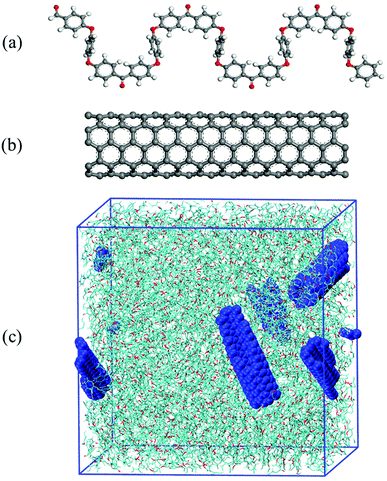
Molecular Dynamics (MD) simulation was employed to calculate both the mechanical property and interfacial property of CNT/PEEK nanocomposites. The initial computational model was made up of both CNT and PEEK molecule chains on the platform of Material Studio 7.0 (Accelrys, U.S.). In the representative volume element (RVE), the matrix of nanocomposites consisted of 10 chains of PEEK with 60 repeat units of PEEK in each chain, making a molecular weight of 17![[thin space (1/6-em)]](https://www.rsc.org/images/entities/char_2009.gif) 000. (5,5) armchair CNT with 240 carbon atoms was selected as reinforcement of PEEK polymer. The diameter and length of CNT were 6.78 Å and 29.51 Å, respectively. The CNTs were randomly located in the RVE. The sizes of the computational cell were 72 Å × 72 Å × 72 Å and three-dimensional periodic boundary condition was set (Fig. 1).
000. (5,5) armchair CNT with 240 carbon atoms was selected as reinforcement of PEEK polymer. The diameter and length of CNT were 6.78 Å and 29.51 Å, respectively. The CNTs were randomly located in the RVE. The sizes of the computational cell were 72 Å × 72 Å × 72 Å and three-dimensional periodic boundary condition was set (Fig. 1).
A complete MD simulation procedure includes the initial configurations establishment, energy minimization, equilibrium simulation the dynamic simulation and results analysis.36 GROMACS37 was used to perform all the molecular simulations, as well as the tensile deformation and fiber pull-out simulation. GROMOS 54A7 (ref. 38) force field was used to describe the atomic interactions in the CNT/PEEK nanocomposite. Comparing to other popular MD simulation packages, GROMACS has the advantage in computational efficiency for large-scale systems, and can also handle complex polymer systems. The force field parameters of PEEK monomers were developed on the platform of Automated force field Topology Builder (ATB),39 and the parameters for CNT model was obtained from literature.31
2.1 MD simulation of CNT/PEEK system
In order to avoid the failure of equilibrium simulation because of the inappropriate initial configuration of the molecular structure, a total energy minimization step was performed to obtain the optimized configurations. This optimization step was done using the steepest descent algorithm with a tolerance of 10 kJ mol−1 nm−1. After geometry optimization, the structure was later equilibrated in the NVT ensemble (1 ns, 300 K).40 Annealing simulations were done in the NVT ensemble. After NVT equilibration, the pressure of the system was stabilized by NPT equilibration41 for another 1 ns. After sequential NVT and NPT equilibration, non-equilibrium MD simulation was taken for 2 ns with a constant uniaxial deformation or fiber displacement to simulate the tensile and fiber pull-out situation.2.2 MD simulation of CNT pull-out
In order to study the interfacial properties between CNT and PEEK, simulation of CNT pull-out from the PEEK matrix was carried out. A nanocomposites RVE that consists of 6 PEEK chains (60 repeat units) and a (5,5) armchair CNT with the length of 49.2 Å and diameter 6.78 Å was developed as shown in Fig. 2(a). The direction of CNT was defined along the X-axis. The CNT was placed in the center of the cell. The energy minimization, NVT equilibration, and NPT equilibration were performed as abovementioned. The equilibrated CNT/PEEK configuration has been shown in Fig. 2(a) and the density of CNT/PEEK nanocomposites was 1.2 g cm−3.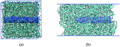 | ||
| Fig. 2 The pull-out configuration after equilibration simulation: (a) 3D periodicity, and (b) 2D periodicity. | ||
In order to pull out the CNT from the PEEK matrix, the periodic boundary condition along the X-axial direction of CNT was removed. Another procedure of sequential energy minimization, NVT equilibration, and NPT equilibration was re-performed in turn to obtain a steady and reasonable initial molecular structure. The equilibrated CNT/PEEK configuration has been shown in Fig. 2(b). To improve computational efficiency, the position of the PEEK matrix was restrained. The CNT was pulled out stepwise from PEEK matrix with a displacement increment of 5 Å along x-axial direction.
In this paper, the IFSS was used to characterize the interfacial properties of CNT/PEEK nanocomposites. The IFSS was determined by the interactional energy between CNT and PEEK included van der Waals and electrostatic forces. The interaction energy of CNT/PEEK was extracted from the output of the pull-out simulation. The interaction energy was defined as follows:
| ΔE = Esystem − (ECNT + EPEEK) | (1) |
 | (2) |
 | (3) |
3. Reinforcement of PEEK by pristine CNTs
Non-equilibrium MD method was used to evaluate the mechanical properties of CNT/PEEK nanocomposites, considering the effects of strain rate, CNT content, and interface between CNT and PEEK matrix. The density of the simulation system is 1.22 g cm−3, which agrees with the experimental characterization (1.263 g cm−3) in literature.43 To obtain the elastic modulus of CNT/PEEK nanocomposite, the system was stretched to a total 20% engineering strain along the x, y and z-direction, respectively. The stress was calculated by the “GROMACS Local Stress 2016” package44 based on the output of direct MD simulation. The internal stress tensor was calculated using the following virial stress expression:
 | (4) |
 | ||
| Fig. 3 (a) The entire stress–strain curve of pure PEEK, (b) initial linear segment stress–strain curve, and (c) variation of elastic modulus and computation time with strain rate. | ||
The effect of strain rate on the elastic modulus of the nanocomposite was investigated in this section. The lower strain rate was needed to ensure loading stability. However, the lower strain rate will result in unaffordable computation time. It is critical to balance calculation time and computational accuracy. A reasonable strain rate value should consider both calculation accuracy and efficiency. The variation of elastic modulus prediction and computation time with different strain rate is shown in the Fig. 3(c). It can be found that, when the strain rate less than 1 × 10⁸ per s, the value of elastic modulus converges, and the computation time increased greatly. Therefore, the strain rate of 1 × 10⁸ per s is selected as the loading condition for all MD simulation in this paper.
In order to evaluate the elastic modulus and strength of uniaxial CNT/PEEK nanocomposite, the Morse potential was applied in the modeling process to describe the breaking of covalent bond breaking the material. 3D periodicity model in Fig. 4(a) was used to calculate the elastic modulus and strength of uniaxial CNT/PEEK nanocomposite. Fig. 4(a) shows the failure configuration of the nanocomposite, and Fig. 4(b) shows a typical stress–strain curve of uniaxial CNT/PEEK nanocomposite along the axial direction of CNT from MD simulation. The elastic modulus was obtained by fitting the slope of the stress–strain curve in strain range (0–0.05). The tensile strength was determined by the maximum stress of the stress–strain curve. The elastic modulus and tensile strength of nanocomposite were predicted to be 24.5 GPa and 2.47 GPa, respectively, which agrees with previous studies,45 also validating the reliability of our MD model in the prediction of mechanical properties of CNT/PEEK nanocomposite.
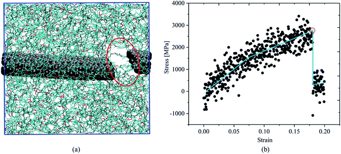 | ||
| Fig. 4 (a) The failure configuration and (b) the stress–strain curve of uniaxial CNT/PEEK nanocomposites. | ||
However, in actual cases, the CNTs were embedded into the polymer as particulate fillers, with the largest size of several hundred micrometers. The uniaxial continuous CNT reinforcement technique for the fabrication of PEEK-based composites is not as mature as short CNT nanocomposites due to manufacturing limits.29 Therefore, we focus on the mechanical characterization of short and random CNT reinforcements in PEEK in this paper.
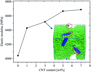
The effect of CNT content on the elastic modulus of CNT/PEEK nanocomposites was investigated at first and the results are provided in Fig. 5. The average elastic modulus of the pure PEEK was predicted to be 4.04 GPa, which agrees with the experimental results (4 GPa) measured by Deng et al.2 When 1 wt% CNT was embedded into the PEEK matrix, a 10% increase in the elastic modulus can be observed Fig. 5. Due to the high modulus of CNT and the coupling interaction between CNT and PEEK, the elastic modulus of nanocomposites was improved significantly by a small number of CNTs comparing to pure PEEK, which also was reported by Zhang et al.46 However, when the CNT content exceeded a certain value, the elastic modulus would not approach the elastic modulus of pristine CNT, which was also reported by experimental characterizations.47,48
In order to explain the reason why mechanical properties of CNT/PEEK composite cannot linearly increase with the content of CNT, the failure conformation of short-fiber CNT/PEEK composites with 3 wt% CNT was extracted and shown in Fig. 5. Destruction regions in the nanocomposites can be observed near the interface between CNT and PEEK, which means that, in the process of uniaxial deformation simulation, micro-cracks near the interface were incubated and continuously grows into the PEEK matrix until the nanocomposite was completely destroyed. As the CNT content increased, the chance of introducing micro-cracks is higher, which knocks down the mechanical performance of the nanocomposites. Therefore, the interfacial strength of CNT–PEEK is significant to modulating the mechanical performance of CNT/PEEK nanocomposite, which will be discussed in the following sections.
4. Modulating the interface between CNT and PEEK
The atoms of CNT are in the neutral state, leading to an ultra-weak van der Waals forces between CNT and PEEK. Therefore, functional groups were grafted onto a carbon nanotube in the MD model to investigate the effects of functional groups on the interfacial properties, as well as the overall mechanical behaviors of CNT/PEEK nanocomposites.A few strategies of functionalization on CNT were developed to improve the interfacial properties of nanocomposites, such as carboxylic groups (–COOH),20 amino groups (–NH2),34 alkyl groups (–C6H11),20 phenyl groups (–C6H5).33 These functional groups can increase the surface roughness of CNT and the interaction forces with PEEK matrix, therefore, improving the IFSS in the CNT/PEEK composites. In this paper, we attempted to build multiple H-bond between the functional groups and PEEK matrix to achieve the interfacial toughening. The ketones in PEEK can perform as the acceptor of H-bond, and molecular groups need to be added to the CNT as the donator in an H-bond. Our attempt is to use amide groups to functionalize the CNT and form H-bond between the CNT and PEEK, which would further improve the IFSS in the nanocomposites. The CNT pull-out simulation was conducted to evaluate the interfacial properties of the CNT/PEEK nanocomposites and the pull-out energy was used to calculate the IFSS. The effects of functionalization strategy on IFSS are discussed in this part.
Three models were developed to validate the effect of functionalization on the IFSS of nanocomposites, including pristine CNT/PEEK, direct amino functionalized CNT/PEEK and 4,4-diaminodiphenyl methane (DDM)49 functionalized CNT/PEEK. Fig. 6 shown the schematic of the three models: (a) pristine CNT, (b) 8 aminos-modified CNT, and (c) 4 DDMs modified randomly on the outside surface CNT. In the last two models, the amino number per unit length of CNT is the same to make a fair comparison. A whole process of energy minimization, equilibration, and MD simulation was identically performed on each model until the pull-out simulation of different CNT/PEEK nanocomposites.
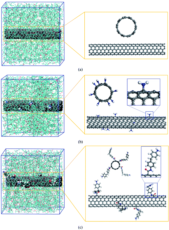 | ||
| Fig. 6 The molecular configuration of (a) the pristine CNT/PEEK, (b) the functionalized CNT/PEEK nanocomposites by aminos and (c) the CNT functionalized by DDMs. | ||
The snapshots of the atomic configuration of nanocomposite during the pull-out process of pristine CNT, NH2-CNT and DDM-CNT are shown in Fig. 7(a), (b) and (c), respectively. The interaction energy between CNT and PEEK during the pull-out process at 300 K is shown in Fig. 8(a). As the CNT was pulled out constantly, the interaction energy between CNT and PEEK decrease approximately linearly. When the CNT was pulled out completely, the interaction energy decreases to zero. Similar results were reported the CNT/epoxy system by Guru et al.33 and Yang et al.,50 providing validation for the simulation performed in this paper. However, before the CNT was pulled out 2 nm, the interaction energy between DDM-CNT and PEEK decrease significantly. After the DDM-CNT was pulled out 2 nm, the interaction energy between DDM-CNT and PEEK decrease approximately linearly, which was similar with CNT and NH2-CNT.
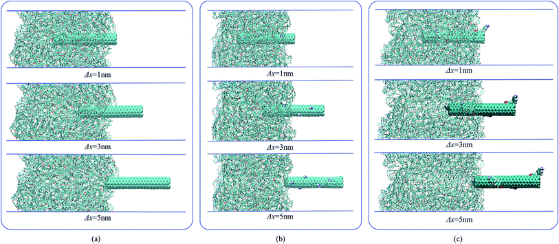 | ||
| Fig. 7 The snapshots of the atomic configuration of nanocomposite during pull-out of (a) pristine CNT, (b) NH2-CNT and (c) DDM-CNT. | ||
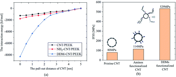 | ||
| Fig. 8 Comparisons of (a) the interaction energy and (b) IFSS between pristine CNT and functionalized CNT. | ||
Comparisons of IFSS between functionalized CNT and pristine CNT nanocomposites room temperature were shown in Fig. 8(b). The value of IFSS in the amino-functionalized CNT/PEEK (NH2-CNT/PEEK) nanocomposite was 114 MPa at room temperature, which was 42.5% higher than that of pristine CNT/PEEK nanocomposites. The value of IFSS of the DDMs functionalized CNT/PEEK (DDM-CNT/PEEK) nanocomposites was 529 MPa, which is significantly larger than the pristine CNT/PEEK nanocomposites and NH2-CNT/PEEK nanocomposites, indicating that the interfacial properties of CNT/PEEK nanocomposites can be improved significantly by using aminos and DDMs to functionalize the CNTs, similar results have been reported for CNT/PE system.20 The sidechain of DDM-modified nanotubes is much longer than the –NH2-modified nanotubes, which results in higher VDW interaction between the functional groups and PEEK matrix as well as H-bond interaction. Therefore, the IFSS of DDM-modified nanotubes was significantly improved comparing to the other two types of nanotube reinforcements.
5. Alternating the mechanical property of CNT/PEEK nanocomposite
During the CNT pull-out simulation, the interfacial interaction forces of the pristine CNT nanocomposites only included van der Waals forces between the CNT and PEEK, as shown in Fig. 9(a). The interfacial interaction forces of the functionalized CNT nanocomposites included: (I) van der Waals forces between the CNT and PEEK, (II) van der Waals forces and the week electrostatic force between the functional groups and PEEK, and (III) the H-bond interaction between amino groups and the ketones of PEEK, as shown in Fig. 9(b) and (c). The DDMs group had much longer chain length and more atoms than the amino only chain, which increased the contact area between functionalized CNT and PEEK chains, and led to much stronger interfacial force, therefore, a higher IFSS. Because the DDMs group were inserted in the PEEK, the CNT was pulled out from the PEEK matrix together with the DDMs group. Therefore, multilevel embedding microstructure needed to be destroyed during the pull-out process, which increased the IFSS as shown in Fig. 9(c). In addition, the interfacial interaction of the NH2-CNT/PEEK and DDM-CNT/PEEK nanocomposites also include H-bonds interaction, which further toughens the interface. As the pull-out distance of CNT increased, the number of H-bonds fluctuate constantly. It was indicated that the H-bonds were broken and formed during the pull-out process and acceptors of H-bonds were exchanged incessantly, which increased the pull-out energy.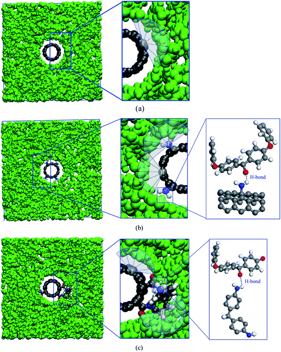 | ||
| Fig. 9 Schematics of the interaction between CNT and PEEK for (a) the pristine CNT/PEEK nanocomposites, (b) the NH2-CNT/PEEK nanocomposites, and (c) the DDM-CNT/PEEK nanocomposites. | ||
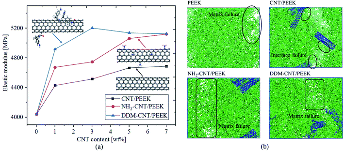
Functionalization of CNT had been experimentally verified to enhance the mechanical performances of the few types of nanocomposites,51 herein, the effect of amino groups on the elastic modulus of CNT/PEEK nanocomposites will be discussed. The DDM-functionalization and amino-only functionalization of CNTs has shown higher interfacial strength than pristine CNTs (Fig. 8). Therefore, both of the DDM-functionalization and amino-only-functionalization strategy are adopted to validate the impact of amino groups on the mechanical performance of CNT/PEEK nanocomposite in this section.
Each molecular model CNT in Section 4 was functionalized with 8 amino groups, which is kept the same in the evaluation models of elastic modulus in this section. The elastic modulus of CNT/PEEK, NH2-CNT/PEEK and DDM-CNT/PEEK nanocomposites with different CNT content is calculated with the same procedure as above-mentioned and the results are provided in Fig. 10(a). It can be found that, by the amino-modification and DDM-modification, the enhancement of elastic modulus by CNTs increases from 15% (pristine CNT) to 27.5% (NH2-CNT and DDM-CNT), which agrees with our prediction of mechanical enhancement by the amino modification. The failure region of pristine CNT/PEEK nanocomposites is mostly located near the interface between CNT-reinforcements and PEEK matrix (Fig. 10(b)). However, for NH2-CNT and DDM-CNT modified composite the failure surface leaves the CNT–PEEK interface, and is located evenly in the PEEK matrix (Fig. 10(b)). While the pristine CNTs were inserted into the PEEK matrix, the weak interface between CNT and PEEK induces micro-cracks in the nanocomposite. By the amino-modification and DDM-modification, these weakened material points in the nanocomposites are strengthened by applying molecular bonding of H-bonds, which, therefore, improved the mechanical performance of the whole material.
6. Conclusion
In the present study, with the target of engineering the mechanical performance of CNT/PEEK nanocomposite for structural applications, molecular dynamics (MD) method is employed to predict the mechanical behaviors of CNT/PEEK nanocomposites and study the corresponding failure mechanism. The effects of strain rate, CNT content on the elastic modulus of composites are discussed at first. After configurational analysis, the interfacial failure between CNT and PEEK is identified as the reason for limited performance-enhancement while more than 5 wt% CNT is added to PEEK. Amino modification strategy is brought to the design of CNT/PEEK nanocomposite, to improve the interfacial strength, which, therefore, improves the overall mechanical performance of CNT PEEK nanocomposite. MD simulation validated that the addition of amino groups significantly improved the IFSS in CNT/PEEK nanocomposite, as well as the elastic modulus.To sum up, by the addition of amino groups in the fabrication of CNT/PEEK nanocomposite, the potential of mechanical enhancement of PEEK by CNT reinforcement can be significantly improved. Future ultra-fine molecular design of the CNT processing and molecular chain modification of PEEK (such as grafting side chains and copolymer design) can provide more options in the engineering of mechanical properties of CNT/PEEK nanocomposites for their application as lightweight structural components.
Conflicts of interest
The authors declare no conflict of interest.Acknowledgements
The authors would like to thank the support from the National Natural Science Foundation of China (11802051, 11802053, and 51790172), ARC Discovery Project (DP170102861) and Start-up Funding from DUT (DUT18RC(3)031).References
- J. Sandler, P. Werner, M. S. P. Shaffer, V. Demchuk, V. Altstädt and A. H. Windle, Composites, Part A, 2002, 33, 1033–1039 CrossRef.
- F. Deng, T. Ogasawara and N. Takeda, Compos. Sci. Technol., 2007, 67, 2959–2964 CrossRef CAS.
- J. A. Puértolas, M. Castro, J. A. Morris, R. Ríos and A. Ansón-Casaos, Carbon, 2018, 141, 107–122 CrossRef.
- A. M. Díez-Pascual, G. Martínez, M. T. Martínez and M. A. Gómez, J. Mater. Chem., 2010, 20, 8247–8256 RSC.
- W. A. Pisani, M. S. Radue, S. Chinkanjanarot, B. A. Bednarcyk, E. J. Pineda, K. Waters, R. Pandey, J. A. King and G. M. J. P. Odegard, Polymer, 2019, 163, 96–105 CrossRef CAS.
- L. Pan and U. Yapici, Adv. Compos. Mater., 2016, 25, 359–374 CrossRef CAS.
- V. Gupta, R. B. Mathur, T. L. Dhami and O. P. Bahl, High Perform. Polym., 2002, 14, 285–292 CrossRef CAS.
- L. Ye, K. Friedrich, J. Kästel and Y.-W. Mai, Compos. Sci. Technol., 1995, 54, 349–358 CrossRef CAS.
- Z. Xu, Z. Mei, S. H. Gao, G. Wang, S. Zhang and J. Luan, Polym. Compos., 2017, 40, 56–69 CrossRef.
- R. Rattan and J. Bijwe, Mater. Sci. Eng., A, 2006, 420, 342–350 CrossRef.
- J. Chen, K. Wang and Y. Zhao, Compos. Sci. Technol., 2018, 154, 175–186 CrossRef CAS.
- L. Guo, H. Qi, G. Zhang, T. Wang and Q. Wang, Composites, Part A, 2017, 97, 19–30 CrossRef CAS.
- J. P. Lu, J. Phys. Chem. Solids, 1997, 58, 1649–1652 CrossRef CAS.
- M. J. Treacy, T. Ebbesen and J. Gibson, Nature, 1996, 381, 678–680 CrossRef CAS.
- E. W. Wong, P. E. Sheehan and C. M. Lieber, Science, 1997, 277, 1971–1975 CrossRef CAS.
- P. Bei, L. Mark, Z. Peter, L. Shuyou, S. L. Mielke, G. C. Schatz and H. D. Espinosa, Nat. Nanotechnol., 2008, 3, 626–631 CrossRef PubMed.
- D.-L. Shi, X.-Q. Feng, Y. Y. Huang, K.-C. Hwang and H. Gao, J. Eng. Mater. Technol., 2004, 126, 250–257 CrossRef CAS.
- W. Zhao, T. Li, Y. Li, D. J. O'Brien, M. Terrones, B. Wei, J. Suhr and X. Lucas Lu, J. Materiomics, 2018, 4, 157–164 CrossRef.
- J. Gou, Z. Liang, C. Zhang and B. Wang, Composites, Part B, 2005, 36, 524–533 CrossRef.
- Q. Zheng, X. Dan, Q. Xue, K. Yan, X. Gao and Q. Li, Appl. Surf. Sci., 2009, 255, 3534–3543 CrossRef CAS.
- A. H. Barber, S. R. Cohen, A. Eitan, L. S. Schadler and H. D. Wagner, Adv. Mater., 2006, 18, 83–87 CrossRef CAS.
- T. Tsuda, T. Ogasawara, F. Deng and N. Takeda, Compos. Sci. Technol., 2011, 71, 1295–1300 CrossRef CAS.
- T. Li, A. Oloyede and Y. Gu, Appl. Phys. Lett., 2014, 104, 023702 CrossRef.
- T. Li, A. Oloyede and Y. Gu, J. Appl. Phys., 2013, 114, 214701 CrossRef.
- T. Li, Y. Gu, X.-Q. Feng, P. K. Yarlagadda and A. Oloyede, J. Appl. Phys., 2013, 113, 194701 CrossRef.
- M. Tang, T. Li, N. S. Gandhi, K. Burrage and Y. T. Gu, Biomech. Model. Mechanobiol., 2017, 16, 1023–1033 CrossRef PubMed.
- A. Singh and D. Kumar, J. Mol. Model., 2018, 24, 178 CrossRef PubMed.
- S. Rouhi, Y. Alizadeh and R. Ansari, J. Mol. Model., 2016, 22, 1–11 CrossRef CAS PubMed.
- I. A. Kinloch, J. Suhr, J. Lou, R. J. Young and P. M. Ajayan, Science, 2018, 362, 547–553 CrossRef CAS PubMed.
- S. Haghighatpanah and K. Bolton, Comput. Mater. Sci., 2013, 69, 443–454 CrossRef CAS.
- Y. Li, S. Wang, Q. Wang and M. Xing, Composites, Part B, 2018, 133, 35–41 CrossRef CAS.
- S. Sharma, R. Chandra, P. Kumar and N. Kumar, JOM, 2016, 68, 1717–1727 CrossRef CAS.
- K. Guru, S. Mishra and K. Shukla, Appl. Surf. Sci., 2015, 349, 59–65 CrossRef CAS.
- K. Sharma, K. S. Kaushalyayan and M. Shukla, Comput. Mater. Sci., 2015, 99, 232–241 CrossRef CAS.
- R. Chawla and S. Sharma, Compos. Sci. Technol., 2017, 144, 169–177 CrossRef CAS.
- T. Li, Y. Gu, A. Oloyede and P. K. Yarlagadda, Comput. Methods Biomech. Biomed. Eng., 2014, 17, 616–622 CrossRef PubMed.
- H. J. C. Berendsen, D. van der Spoel and R. van Drunen, Comput. Phys. Commun., 1995, 91, 43–56 CrossRef CAS.
- N. Schmid, A. P. Eichenberger, A. Choutko, S. Riniker, M. Winger, A. E. Mark and W. F. van Gunsteren, Eur. Biophys. J., 2011, 40, 843 CrossRef CAS PubMed.
- K. B. Koziara, M. Stroet, A. K. Malde and A. E. Mark, J. Comput.-Aided Mol. Des., 2014, 28, 221–233 CrossRef CAS PubMed.
- T. Tsafack, J. M. Alred, K. E. Wise, B. Jensen, E. Siochi and B. I. Yakobson, Carbon, 2016, 105, 600–606 CrossRef CAS.
- X. Peng and S. A. Meguid, Comput. Mater. Sci., 2017, 126, 204–216 CrossRef CAS.
- B. Yu, S. Fu, Z. Wu, H. Bai, N. Ning and F. Qiang, Composites, Part A, 2015, 73, 155–165 CrossRef CAS.
- B. Nandan, D. L. Kandpal and N. G. Mathur, Polymer, 2003, 44, 1267–1279 CrossRef CAS.
- A. Torres-Sánchez, J. M. Vanegas and M. Arroyo, Phys. Rev. Lett., 2015, 114, 258102 CrossRef PubMed.
- M. Mahboob and M. Z. Islam, Comput. Mater. Sci., 2013, 79, 223–229 CrossRef CAS.
- S. Zhang, H. Wang, G. Wang and Z. Jiang, Appl. Phys. Lett., 2012, 101, 012904 CrossRef.
- A. M. Díez-Pascual, M. Naffakh, J. M. González-Domínguez, A. Ansón, Y. Martínez-Rubi, M. T. Martinez, B. Simard and M. A. Gómez, Carbon, 2010, 48, 3500–3511 CrossRef.
- T. Ogasawara, T. Tsuda and N. Takeda, Compos. Sci. Technol., 2011, 71, 73–78 CrossRef CAS.
- P. K. S. Mural, A. Banerjee, M. S. Rana, A. Shukla, B. Padmanabhan, S. Bhadra, G. Madras and S. Bose, J. Mater. Chem. A, 2014, 2, 17635–17648 RSC.
- S. Yang, J. Choi and M. Cho, Compos. Struct., 2015, 127, 108–119 CrossRef.
- M.-G. Kim, J.-B. Moon and C.-G. Kim, Composites, Part A, 2012, 43, 1620–1627 CrossRef.
| This journal is © The Royal Society of Chemistry 2019 |

