 Open Access Article
Early stages of phase selection in MOF formation observed in molecular Monte Carlo simulations†
Stephen A. Wells *a,
Naomi F. Cessfordb,
Nigel A. Seatonc and
Tina Düren
 *a
*a
aCentre for Advanced Separations Engineering, Department of Chemical Engineering, University of Bath, Bath, UK. E-mail: saw42@bath.ac.uk; t.duren@bath.ac.uk
bInstitute for Materials and Processes, School of Engineering, University of Edinburgh, Edinburgh, UK
cAbertay University, Bell Street, Dundee, UK
First published on 8th May 2019
Abstract
Metal–organic frameworks (MOF) comprising metal nodes bridged by organic linkers show great promise because of their guest-specific gas sorption, separation, drug-delivery, and catalytic properties. The selection of metal node, organic linker, and synthesis conditions in principle offers engineered control over both structure and function. For MOFs to realise their potential and to become more than just promising materials, a degree of predictability in the synthesis and a better understanding of the self-assembly or initial growth processes is of paramount importance. Using cobalt succinate, a MOF that exhibits a variety of phases depending on synthesis temperature and ligand to metal ratio, as proof of concept, we present a molecular Monte Carlo approach that allows us to simulate the early stage of MOF assembly. We introduce a new Contact Cluster Monte Carlo (CCMC) algorithm which uses a system of overlapping “virtual sites” to represent the coordination environment of the cobalt and both metal–metal and metal–ligand associations. Our simulations capture the experimentally observed synthesis phase distinction in cobalt succinate at 348 K. To the best of our knowledge this is the first case in which the formation of different MOF phases as a function of composition is captured by unbiased molecular simulations. The CCMC algorithm is equally applicable to any system in which short-range attractive interactions are a dominant feature, including hydrogen-bonding networks, metal–ligand coordination networks, or the assembly of particles with “sticky” patches, such as colloidal systems or the formation of protein complexes.
Introduction
Metal–organic frameworks (MOFs) are a class of porous materials consisting of metal ions (nodes) complexed by organic ligands (linkers) to form a continuous framework. Since the introduction of the MOF designation1–3 by Yaghi et al., MOFs have attracted considerable attention due to their crystal engineering potential. The choice of node and linker offers, in principle, control over both the pore geometry and the chemical properties of the framework, promising a new generation of functional porous materials for sensing, catalysis, filtration and sorption applications.4,5 Molecular simulation methods, including molecular dynamics (MD) and molecular or coarse-grained Monte Carlo (MC) approaches, are now well established for MOF characterisation and the prediction of their performance in e.g. adsorption applications.6–8 Simulations of MOF nucleation, formation, and the growth of crystals and thin films, in contrast, are less well developed. Promising results have been obtained using MD simulations with both explicit solvent models,9 showing the formation of a recognisable ZIF building unit; and implicit solvent models,10–12 showing the formation of random or ordered 2D and 3D MOF-like networks with a specialised MD protocol. The insight from such simulations will be invaluable in interpreting experimental data on MOF formation and growth mechanisms,13 and in the development of targeted synthesis approaches for MOFs for applications. Modelling the formation of MOFs is particularly challenging, as we are dealing with highly porous, directionally bonded frameworks, in which both solvent and ligand molecules may play structural as well as templating roles, and the formation process may involve chemical reaction steps. Here, we use molecular simulations to explore the first stages of nucleation and growth of MOF structures under synthesis conditions, in a polyphasic system where multiple structural phases can be produced from the same building units.We make use of cobalt succinate MOFs, formed by the assembly of cobalt (Co2+) ions and succinate (COO–CH2–CH2–COO–) anions, as our proof-of-concept system to understand the influence of synthesis conditions on the formation of different frameworks. Multiple structural phases have been identified in hydrothermal syntheses14–16 using aqueous mixtures of cobalt hydroxide and succinic acid as ingredients, comprising seven distinct frameworks with markedly different topologies depending on the system temperature and the ratio of metal to ligand. Capturing the formation of these topologically distinct structures from the same components under different synthesis conditions provides an important challenge for our simulations. The cobalt ions are, in all the crystal structures, octahedrally coordinated by some combination of succinate carboxylate oxygens, solvent water oxygens, or framework oxygens or hydroxide groups. In general, phases produced at higher temperatures or with a greater proportion of cobalt are characterised by a greater degree of metal–metal association, that is, adjacent cobalt coordination octahedra with one, two or three oxygens in common.
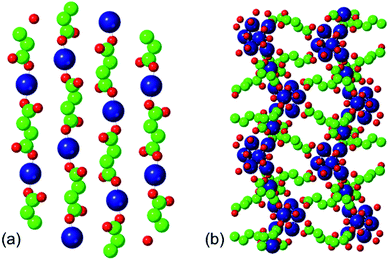
The two phases that we investigate in this study are the low-temperature phases A and F illustrated in Fig. 1. Both are synthesised at 348 K. Phase A, produced at higher [succinate]![[thin space (1/6-em)]](https://www.rsc.org/images/entities/char_2009.gif) :
:![[thin space (1/6-em)]](https://www.rsc.org/images/entities/char_2009.gif) [cobalt] ratios, is characterised by linear chains of alternating metal and ligand units. The connectivity of these chains is one-dimensional and each cobalt ion is coordinated by two ligands and four water molecules. Adjacent, parallel chains are linked by hydrogen bonding between these water molecules. Phase F, produced at lower [succinate]
[cobalt] ratios, is characterised by linear chains of alternating metal and ligand units. The connectivity of these chains is one-dimensional and each cobalt ion is coordinated by two ligands and four water molecules. Adjacent, parallel chains are linked by hydrogen bonding between these water molecules. Phase F, produced at lower [succinate]![[thin space (1/6-em)]](https://www.rsc.org/images/entities/char_2009.gif) :
:![[thin space (1/6-em)]](https://www.rsc.org/images/entities/char_2009.gif) [cobalt] ratios (i.e. with a higher proportion of metal), is characterised by linear chains of linked metal octahedra; these chains are linked to one another by bridging succinate ligands.
[cobalt] ratios (i.e. with a higher proportion of metal), is characterised by linear chains of linked metal octahedra; these chains are linked to one another by bridging succinate ligands.
The assembly of a MOF from its components involves the reversible formation of associations between metal and ligand units. In this paper, we develop a molecular Monte Carlo simulation approach suited to describing the assembly process. Our molecular modelling makes use of potentials of mean force (PMFs) derived from fully atomistic explicit-solvent interactions, so that we can use implicit-solvent simulations while retaining local solvent structuring effects. A system of overlapping “virtual sites” represents the coordination environment of the metal ions and allows both metal–metal and metal–ligand associations to develop spontaneously. These site overlaps also motivate a simple collective move algorithm, allowing smaller clusters to aggregate once they have formed, and are used to identify clusters with topologies appropriate to particular structural phases. We apply this Contact Cluster Monte Carlo (CCMC) approach to investigate the composition dependence of the production of phases A and F in cobalt succinates.
Simulation methods
Molecular models and potentials of mean force
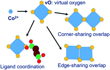
In our MC simulations the succinate ligand is represented as a rigid molecular object made up of three atom types: carboxylate oxygen (O), carboxylate carbon (C) and aliphatic –CH2– group carbon (CH) using a united-atom approach. The cobalt is represented, not as an isolated spherical ion, but as a polyhedral object consisting of a central cobalt ion and a surrounding octahedron of “virtual oxygen” (vO) sites representing its coordination. The physical interpretation of the vO sites depends on the local molecular geometry. In an isolated cobalt object, we assume that vO sites are occupied by implicit solvent water molecules. When vO sites from different cobalt objects overlap, we interpret this as the formation of a metal–oxygen–metal bridge. Coordination of metal by ligand is represented by the overlap of a vO site by a ligand O atom. The model is illustrated in Fig. 2.The system of virtual sites is similar in principle to the cationic dummy atom (CaDA) approach17–20 sometimes used in molecular dynamics simulations, as for example in the work of Yoneya et al.,10–12 to represent the coordination geometry around a metal centre. However, our virtual sites are more general, being interaction sites for PMFs rather than charge sites for Coulomb interactions. In particular, our model permits the overlap of virtual sites to represent the association of metal centres through a bridging oxygen species, allowing both metal–metal and metal–ligand interactions, whereas CaDA represents only metal–ligand interactions.
The effective energy of interaction between the various sites in our implicit-solvent model is represented by a set of PMFs derived from all-atom empirical-potential Monte Carlo simulations.21 We emphasise that our potentials are derived systematically on physical grounds, without “tuning” to favour the formation of any particular MOF structure. These simulations, carried out using a modified version of the MUSIC code,22 made use of the TIP3P water model23 and appropriate force field parameters for the divalent cobalt ion24 and for the succinate ion, using the OPLS-UA forcefield25,26 supplemented by the OPLS-AA force field where necessary.27–29 The simulation temperature was 348 K, corresponding to the experimental synthesis of phases A and F. Electrostatic interactions were handled in real space using the Wolf method.30,31 For every pair of interacting atom types from the set (Co, C, CH, O) a PMF was determined using umbrella sampling and the Weighted Histogram Analysis Method (WHAM).32–34 Force field parameters are tabulated, and additional details of the MC simulations are given in ESI S.2.†
All of the PMFs used in this study are provided as a text file and are discussed in ESI S.3.† Most of the resulting PMFs are relatively featureless, displaying strong repulsion at close distances (steric interaction) and near-zero interaction at greater distances once one or more water molecules are found between the atoms. This is as expected in cases where one or both of the atom types have small partial charges. The Co–O interaction, by contrast, displays significant structure, as shown in Fig. 3, largely due to the strong electrostatic interaction between the Co cation and the negatively charged carboxyl oxygen. The most important features are a strongly attractive well at a Co–O distance of about 1.9 Å, defining the coordination of metal by ligand oxygen, and a second, shallower attractive well at around 4 Å, corresponding to the solvent-mediated situation Co–water–O. The two wells are separated by an energy barrier at around 2.5 Å, corresponding to the unfavourable geometry where the oxygen species is not close to the metal but there is no room for a water molecule between them. The existence of this second attractive well shows how the PMFs capture solvent structuring and templating effects that can be highly significant in MOF formation. Such structuring is frequently neglected in implicit-solvent MD simulations where the solvent is represented only with a range-dependent dielectric constant.10 To make use of this potential in our virtual site model, we redefine the Co–O interaction as an interaction between vO of the cluster and O of the linker. A succinate oxygen interacts only with the closest vO site belonging to a given Co ion and the local attractive well corresponds to a zero vO–O separation. This potential therefore favours colocation of succinate oxygen and vO sites, allowing the ligand to coordinate the metal.
Our model also requires an attractive vO–vO interaction, favouring a zero vO–vO distance, in order to generate metal–metal associations as seen in the denser phases. In this case the overlap of vO sites represents the presence of a bridging oxygen species between the metal ions. This vO–vO interaction is absent from the set of calculated PMFs and so we employ a scaling of the vO–O interaction, as follows. A single vO–vO interaction represents two interactions between Co2+ and the bridging oxygen species, implying a factor of 2; and we assume that the bridging species is a hydroxyl with charge qOH = −1, whereas the charge of a carboxylate oxygen in the MC simulations is qO = −0.8. Under the assumption that the Coulomb energy is dominant in this interactions, this gives a scaling factor of 2 × (1/0.8) = 2.5. Preliminary testing (see ESI S.4†) confirmed that this vO–vO potential allows metal–metal associations to develop, whereas a smaller scaling factor does not provide a sufficient attractive interaction.
Steric radii for clash exclusion are assigned to the atomic types as specified in ESI S.5.† A vO site is, however, permitted to overlap freely with other vO or with succinate O sites. In our analysis of the results, two objects are considered to be clustered together if a vO site in one object has a centre-to-centre distance of less than 0.5 Å with a vO or O site in the other, putting the two sites within the short-range attractive well of the PMF. The resulting cluster geometries can then be assessed for their similarity to phases A and F in terms of structural motifs.
Collective move scheme
In order for small clusters to join together during the aggregation process, the Monte Carlo move scheme must include collective moves in which multiple objects move as a single unit. The construction of such collective moves requires some care. The essential criterion for any valid Monte Carlo simulation is that of balance;35 in equilibrium, the rate at which moves occur into a state i, from all other states, must equal the rate at which they occur from i, into all other states. In molecular Monte Carlo simulations it is usual to impose the stricter condition of detailed balance, which provides that in an equilibrium microstate i, the number of moves accepted from i to each other microstate j must equal the number accepted from j to i. This can be achieved by any move scheme constructed as follows. The probabilities of the system being in microstates i, j are P(i) and P(j) respectively. There is a probability of a move from i to j being proposed, PPROP(ij); and a probability of that move being accepted, PACC(ij). The corresponding probabilities for the move from j to i are PPROP(ji) and PACC(ji). Detailed balance is obeyed provided that| P(i)PPROP(ij)PACC(ij) = P(j)PPROP(ji)PACC(ji) |
In the general case (see for example chapter 15 of Frenkel and Smit36) the probabilities can also include a Jacobian factor reflecting non-uniform sampling of phase space. This can arise from a change of variables and/or from the introduction of holonomic constraints between interacting bodies. In the present case, however, no holonomic constraints are introduced between interacting bodies, and so no explicit Jacobian is applied. We note that for single-object moves, PPROP is just a constant representing the probability of choosing one object from the complete list of objects in the system, and so
| PACC(ij)/PACC(ji) = P(j)/P(i) |
In the standard Metropolis Monte Carlo scheme, the ratio of the acceptance probabilities is set to the inverse of the Boltzmann energetic factor between j and i, that is exp(−ΔEij/kT), so as to sample microstates in proportion to their thermodynamic probability.
Many approaches to clustering and collective moves are possible, as discussed by e.g. Frenkel and Smit,36 and multiple clustering approaches for collective moves in MC have been reported in the literature. The Virtual Move Monte Carlo (VMMC) collective move approach of Whitelam and Geissler,37,38 its convenient algorithmic presentation by Ruzicka and Allen,39 and the very similar energetic clustering approach of Bhattacharyay and Troisi,40 as well as the rejection-free cluster formation algorithms of Luijten et al.,41–43 have been used to describe collective moves in, for example, simulations of colloidal fluids44 and the self-assembly of patchy particles representing proteins.45
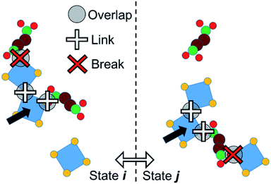
We adopt an approach such that PPROP(ij) will equal PPROP(ji) by construction, retaining the Metropolis energetic criterion unchanged. For clarity of discussion, we define the following terms. An “object” is a single molecular entity, made up of multiple atomic sites. All Monte Carlo moves begin with the selection of one object. A “cluster” is a group of objects moving together as a single unit in a collective move. A “contact” between two different objects signifies close proximity between a site on one object and a site on the other, such that a favourable interaction would be expected. In our model, certain objects include “virtual sites” and close contacts are represented by the overlap of two virtual sites, or of a virtual site with an atomic site, as illustrated in Fig. 2 and 4. We therefore describe our model as Contact Cluster Monte Carlo (CCMC).
An attempt at a collective move begins with the selection of an individual object x in state i. All contacts between x and other objects y can then be tested for cluster formation. A contact will either form a link – so that y joins x in a moving cluster C – or a break, so that y does not join the cluster. The probability that a contact forms a link is a constant user-defined parameter PLINK. When an object joins the cluster C, it is tested for contacts with any objects that are not yet members of C until no new contacts are proposed. The end result is a cluster C bounded, in state i, by a set of breaks Bi. This set may of course be null. The probability of such a cluster being formed in state i can be notionally divided into the probability of forming links within the cluster, P(C), and the probability of not forming links in the breaks, P(Bi).
A collective move of the cluster (in general, a combination of a displacement and a rotation) generates state j. The internal geometry of the cluster is unchanged. However, its boundary is now a different set of breaks Bj (which may of course be null, if C forms no new contacts in j). We therefore penalise the probability of proposing this cluster move, using a factor P(Bj). If Bj involves n contacts, this probability is given by
| P(Bj) = (1 − PLINK)n. |
The move is rejected if a random number selected uniformly from the range 0 to 1 is greater than P(Bj). Clearly if n = 0 then P(Bj) = 1 and the proposed move is not rejected. With this factor, the probability of proposing a cluster move from i to j is identical to that of the reverse move from j to i, being given by P(Bi)P(C)P(Bj) in both cases, and detailed balance is maintained.
As a result of this penalty, the results of the simulation are notably insensitive to the value of PLINK. Higher values favour the formation of larger moving clusters, but make it less likely that cluster moves will lead to new overlaps. A default of PLINK = 0.5 is effective (see ESI S.1†). We note that, in lattice Monte Carlo simulations of surfactant assembly carried out by Wu et al.,46 a similar cluster scheme with PLINK = 1.0 was used in order to forbid clusters from joining together, as an approximation of electrostatic repulsion between micelles.
Note that the energetic clustering methods37,40 allow particles to move along local potential energy gradients, and can therefore be used to approximate the dynamical evolution of a system.38 Since CCMC does not probe these local gradients it does not have this quasi-dynamic behaviour. As such, our simulations probe the energetic landscape of self-assembly rather than approximating the molecular dynamics thereof. The differences between CCMC and energetic clustering methods are discussed in more detail in ESI S.7.† CCMC is applicable to any system in which such short-range attractive interactions are a dominant feature, including hydrogen-bonding networks, metal–ligand coordination networks, or the assembly of particles with “sticky” patches, such as colloidal systems or the formation of protein complexes.
The representation of the cobalt coordination environment by the octahedron of virtual oxygen sites, and the set of vO–vO and vO–O interactions, are designed to represent the chemistry of the cobalt succinate system. By construction the system permits the formation of all the metal–metal and metal–ligand associations found in cobalt succinate structures and shown in Fig. 2, while not permitting inappropriate ligand–ligand direct associations. Other MOF systems with different chemistries would require adaptation of the scheme. For example, a representation of a Zeolitic Imidazolate Framework47 (ZIF) would involve a tetrahedral coordination of Zn ions by virtual nitrogens which can be overlapped by the real nitrogen atoms of the ligand; and in this case no attractive interaction between two virtual nitrogen sites would be required as this system does not display metal–metal association. The clustering approach shown in Fig. 4, meanwhile, is capable of moving clusters of arbitrary size and shape and is agnostic about the chemical identities of the clustered objects. It should therefore be very generally applicable without modification.
Implementation of Monte Carlo simulations
The Monte Carlo move sequence, as implemented in our own C++ code, is illustrated in Fig. 5. An initial moving object is chosen at random with equal probability from the list of all objects. If a collective move is attempted, the moving entity is a linked cluster generated starting with the selected object. Note that this entity may still be a single object, if no links are formed in the cluster formation process. The probability of attempting a collective move, PCOLLECT, and of forming links, PLINK, are both user-defined parameters. In this study we set PLINK = 0.5 as discussed previously, and considered values of PCOLLECT = 0; 0.5; 0.9. A local or a global trial move is selected with 50% probability. In a local move, the moving entity is displaced by up to 0.5 Å along a random vector, and rotated by up to 0.5 radians in a random plane. In a global move, the moving entity is relocated to a random position and orientation anywhere in the simulation box. Random vectors for displacements, orientations and rotations are selected uniformly from the unit sphere, whereas random locations are selected uniformly as fractional coordinates from the unit cube. Local rotations are implemented using the rotor operator of Clifford algebra.48 The rotor makes use of a bivector object, closely analogous to a quaternion and sharing its advantages in the computational representation of rotations.49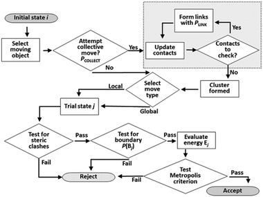 | ||
| Fig. 5 Flow chart of Monte Carlo move sequence. The cluster construction loop (boxed at top right) occurs if a collective move is attempted. | ||
Testing for acceptance occurs in three stages. An initial steric clash test identifies and rejects cases where the move leads to a sterically forbidden overlap of non-bonded atoms. If a collective move generates new contacts, it also has a probability of being rejected to maintain detailed balance as discussed previously. The energy of the trial system is only calculated (using the interatomic PMFs) if the first two stages are passed. The move is then accepted or rejected based on the usual Metropolis energetic criterion. Each simulation run in this work consists of 2 × 10⁸ attempted moves.
The identification of A-like clusters is based on the recognition of linear chains of alternating metal (M) and ligand (L) objects, schematically –M–L–M–L–. The identification of F-like clusters likewise proceeds by a labelling process which recognises groups of multiple M objects bridged by L objects (compare Fig. 1). In a filtering round, only those clusters which contain at least one group of three connected M objects (–M–M–M–) are counted; a strict criterion intended to avoid false-positive identification of F-like clusters. A final point to note is that this identification system results in the clusters L–M–L and M–L–M being identified as “A-like”. However, these three-object clusters can also be identified in the structure of phase F. To avoid false-positive identifications we therefore do not count such clusters of size three as truly A-like, and when assessing how many objects are members of A-like clusters, we consider only clusters of size 4 or more. The details of the phase recognition method are given in ESI S.6.†
Results and discussion
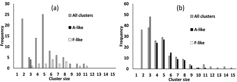
We simulated systems with two compositions: a ligand-poor composition C1, consisting of 400 cobalt units and 80 succinate ligand units, and a ligand-rich composition C2, consisting of 400 cobalt units and 480 ligand units. Compositions C1 and C2 correspond to synthesis conditions for phases F and A, respectively. The simulation box was, for both compositions, a cube of side 113.4 Å, based on the calculated concentrations for the experimental syntheses.21 The initial configurations for the simulations were generated by inserting Co/vO6 octahedra and succinate ligand objects with random locations and orientations in the simulation cell, rejecting any placement which would cause a steric clash with a previously placed object, until the desired composition was achieved.To illustrate the character of the results, we consider simulation runs with PCOLLECT = 0.9. Over the course of the simulations, clusters of overlapping objects appear with gradually increasing size. Fig. 6 shows a census of all overlapping clusters, and of clusters identifiable as A-like or F-like, for both compositions. Clusters occur in this case with sizes from 2 to 15 molecular objects, with smaller clusters being more common.
For the ligand-poor composition C1, for which experimentally phase F is observed, there is no evidence of truly A-like clusters (note that phase identification for A-like clusters of size 3 is ambiguous and therefore only A-like clusters of size 4 or above are counted as described above). F-like clusters occur with sizes from 3 to 11; indeed the single largest cluster in the system is identifiably F-like. In contrast, for the ligand-rich composition C2, for which phase A is observed experimentally, A-like clusters are produced with sizes up to 11. Only a single F-like cluster, of size 10, is observed in this simulation run. Its appearance provides a useful confirmation that our model is capable of producing either type of cluster at any composition.
The different phase selection behaviours for the two compositions is also clear if we count up the number of molecular objects that are contained within identifiably A-like or F-like clusters, as shown in Fig. 7. This census also reveals the brief appearance of some A-like clusters in the ligand-poor composition C1, early on in the simulation, which are subsequently out-competed by F-like clusters.
 | ||
| Fig. 7 Number of molecular objects in identifiably A-like and F-like clusters over the course of a simulation with PCOLLECT = 0.9 at compositions (a) C1 (ligand-poor) and (b) C2 (ligand-rich). | ||
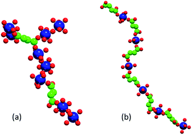
Fig. 8 shows illustrative examples of an F-like cluster formed at composition C1 (note the M–M–M structural motif required for this phase) and of an A-like linear chain formed at composition C2.
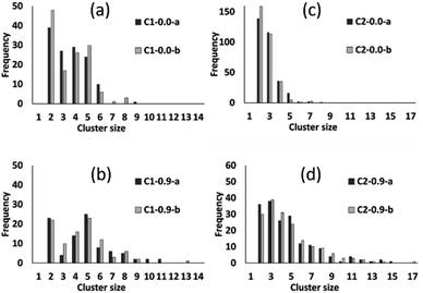
The preceding analysis demonstrates that our modelling approach is successful in capturing the character of syntheses with ligand-rich and ligand-poor compositions. In order to assess the effectiveness and utility of the collective move system, we now compare the results of simulations carried out at compositions C1 and C2 with and without collective moves, for PCOLLECT = 0 or 0.9. In each case we show the results of two independent Monte Carlo runs with different random seeds. Cluster census data in Fig. 9 shows that simulations without collective moves (PCOLLECT = 0; Fig. 9a and d) exhibit kinetic trapping, producing mostly small clusters of sizes 2–5. With collective moves, the simulations are able to produce larger clusters. The contrast is particularly strong at the more densely packed composition C2 (Fig. 9c and d), where the collective move scheme is clearly necessary in order to produce clusters with sizes greater than five.
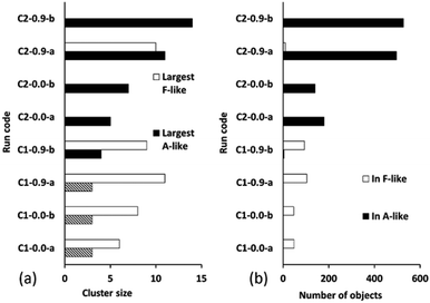
Fig. 10 summarizes the sizes of the largest A-like and F-like cluster produced in each simulation (Fig. 10a) and the total number of objects contained in identifiably A-like and F-like clusters (Fig. 10b). The tendency towards F-like clusters in the ligand-poor composition C1 and towards A-like clusters in the ligand-rich composition C2 clearly exists with or without the use of collective moves. This establishes that the phase selection tendency results from the composition and the potential model, and is not dependent on the collective move system. In composition C1, the use of collective moves slightly favours the formation of larger F-like clusters, and clearly favours the inclusion of more objects into F-like clusters. In composition C2, the effect of collective moves is much more dramatic, doubling the size of the largest A-like clusters, and tripling the number of objects included in clearly A-like clusters (simulations using a PCOLLECT value of 0.5 rather than 0.9 give similar results, shown in detail in ESI S.9†). This underscores the importance of collective moves in Monte Carlo simulations of denser systems to avoid kinetic trapping effects.
Our results provide proof of principle that the CCMC approach is capable of identifying composition-dependent differences in MOF growth topologies. In principle our method can be extended to other MOF systems, although a new set of PMFs are required for each new system. Different MOF chemistries are of course a priority, as facile syntheses of stable MOFs with appropriate pore geometries are a necessity if MOFs are to fulfil their promise as microporous materials in applications.4,5,50 Possible target systems include other MOFs in which different phases can arise from the same building blocks under different reaction conditions, e.g. the chromium terephthalates MIL-101 (ref. 51) and MIL-53.52,53 The flexible chemistry of the Zr6 cluster found in structures such as UiO-66 (ref. 54) would also be of great interest; the coordination of each zinc ion can involve framework oxygen, hydroxide groups, water molecules and carboxylate oxygens, so that the adaptability of the virtual site system should be highly applicable. ZIFs are another important MOF subclass, in which strikingly different zeolite-like framework topologies arise through the use of different imidazolate derivatives as ligands. The interest in this case would be an investigation of the effect of ligand geometry on the initial generation of small clusters and rings.
Furthermore, the CCMC approach is not limited to MOFs, but could also be applied to other systems by taking a very broad definition of what constitutes a ligand. For example, the crystallisation of calcite (CaCo3) from solution is a widely studied system55–57 which could be described in our model by considering the triangular carbonate anion as a ligand.
Conclusions
We have developed and applied methods for molecular Monte Carlo simulations of the initial stages of MOF assembly under synthesis conditions. To model the assembly of metal-coordination polyhedra and ligand molecules, we employ a system of “virtual sites”. This captures the coordination geometry around metal ions and allows metal–solvent, metal–metal and metal–ligand associations to be described with a set of intersite interaction potentials of mean force which capture the structuring effect of the solvent.In simulations of molecular aggregation, collective (cluster) moves are important to avoid severe computational slowdown as small clusters form and grow. We developed a Contact Cluster Monte Carlo (CCMC) algorithm which cleanly separates the cluster formation probability, based on the geometry of local attractive contacts, from the Metropolis energetic criterion for move acceptance. CCMC thus avoids the computational cost of evaluating multiple exponential terms during cluster construction and makes it easy for favourable interactions both to form and to break during cluster construction. The collective move algorithm described here is equally applicable to any model dominated by local attractive interactions, for example hydrogen bonding networks, the assembly of positively and negatively charged groups or the assembly of particles with “sticky” patches, such as colloidal systems or the formation of protein complexes. We therefore anticipate that the algorithm will be of general use in modelling the assembly of framework structures, including MOFs.
In molecular simulations of the cobalt succinate system, a MOF that exhibits different phases depending on the synthesis conditions, our methodology successfully models the aggregation of MOF building units into clusters, producing clusters with topologies characteristic of the experimentally observed A and F phases. The geometric collective move system introduced here is effective in assembling clusters with sizes that are not reached by single-object moves due to kinetic trapping. We observe different cluster topologies depending on the ligand to metal ratio: at high ligand concentration, 1D chains of alternating metal–ligand–metal form, whereas at low ligand concentration metal–metal clusters and chains are linked together by multiply coordinated ligands. This captures the experimental observation of the growth of two distinct phases (“A” and “F”) at moderate temperatures in ligand-rich and ligand-poor batch compositions. We note in particular that our PMFs were obtained systematically and were not “tuned” to produce A-like or F-like clusters. To the best of our knowledge, this is the first time that the spontaneous emergence of two different, experimentally appropriate, topologies, based only on the synthesis conditions has been predicted using molecular simulation and represents an important step forward in the simulation of MOF formation.
Conflicts of interest
There are no conflicts to declare.Acknowledgements
This project has received funding from the European Research Council (ERC) under the European Union's Horizon 2020 research and innovation programme (grant agreement No 648283 “GROWMOF”) and the EPSRC (EP/F009208/1).Notes and references
- O. M. Yaghi and G. M. Li, Abstr. Pap. Am. Chem. Soc., 1995, 209, 284 Search PubMed.
- O. M. Yaghi and H. L. Li, J. Am. Chem. Soc., 1995, 117, 10401–10402 CrossRef CAS.
- O. M. Yaghi, G. M. Li and H. L. Li, Nature, 1995, 378, 703–706 CrossRef CAS.
- H. Furukawa, K. E. Cordova, M. O'Keeffe and O. M. Yaghi, Science, 2013, 341(6149), 1230444 CrossRef PubMed.
- M. D. Allendorf and V. Stavila, CrystEngComm, 2015, 17, 229–246 RSC.
- T. Düren, Y. S. Bae and R. Q. Snurr, Chem. Soc. Rev., 2009, 38, 1237–1247 RSC.
- F. X. Coudert and A. H. Fuchs, Coord. Chem. Rev., 2016, 307, 211–236 CrossRef CAS.
- M. J. Lennox, M. Bound, A. Henley and E. Besley, Mol. Simul., 2017, 43, 828–837 CrossRef CAS.
- D. Biswal and P. G. Kusalik, ACS Nano, 2017, 11, 258–268 CrossRef CAS.
- M. Yoneya, S. Tsuzuki and M. Aoyagi, Phys. Chem. Chem. Phys., 2015, 17, 8649–8652 RSC.
- M. Yoneya, S. Tsuzuki, T. Yamaguchi, S. Sato and M. Fujita, ACS Nano, 2014, 8, 1290–1296 CrossRef CAS PubMed.
- M. Yoneya, T. Yamaguchi, S. Sato and M. Fujita, J. Am. Chem. Soc., 2012, 134, 14401–14407 CrossRef CAS PubMed.
- M. J. Van Vleet, T. T. Weng, X. Y. Li and J. R. Schmidt, Chem. Rev., 2018, 118, 3681–3721 CrossRef CAS PubMed.
- S. H. Jhung, J. H. Lee, P. M. Forster, G. Ferey, A. K. Cheetham and J. S. Chang, Chem.–Eur. J., 2006, 12, 7899–7905 CrossRef.
- P. M. Forster, N. Stock and A. K. Cheetham, Angew. Chem., Int. Ed., 2005, 44, 7608–7611 CrossRef CAS.
- P. M. Forster, A. R. Burbank, C. Livage, G. Ferey and A. K. Cheetham, Chem. Commun., 2004, 368–369 RSC.
- J. Aqvist and A. Warshel, J. Am. Chem. Soc., 1990, 112, 2860–2868 CrossRef.
- Y. P. Pang, K. Xu, J. El Yazal and F. G. Prendergast, Protein Sci., 2000, 9, 2583 CAS.
- Y. P. Pang, Proteins, 2001, 45, 183–189 CrossRef CAS.
- F. Duarte, P. Bauer, A. Barrozo, B. A. Amrein, M. Purg, J. Aqvist and S. C. L. Kamerlin, J. Phys. Chem. B, 2014, 118, 4351–4362 CrossRef CAS PubMed.
- N. F. Cessford, PhD thesis, University of Edinburgh, 2014, https://www.era.lib.ed.ac.uk/handle/1842/17610, accessed 29 April 2019.
- A. Gupta, S. Chempath, M. J. Sanborn, L. A. Clark and R. Q. Snurr, Mol. Simul., 2003, 29, 29–46 CrossRef CAS.
- W. L. Jorgensen, J. Chandrasekhar, J. D. Madura, R. W. Impey and M. L. Klein, J. Chem. Phys., 1983, 79, 926–935 CrossRef CAS.
- C. S. Babu and C. Lim, J. Phys. Chem. A, 2006, 110, 691–699 CrossRef CAS.
- W. L. Jorgensen and J. Gao, J. Phys. Chem., 1986, 90, 2174–2182 CrossRef CAS.
- W. L. Jorgensen, J. D. Madura and C. J. Swenson, J. Am. Chem. Soc., 1984, 106, 6638–6646 CrossRef CAS.
- D. J. Price, J. D. Roberts and W. L. Jorgensen, J. Am. Chem. Soc., 1998, 120, 9672–9679 CrossRef.
- W. L. Jorgensen, D. S. Maxwell and J. TiradoRives, J. Am. Chem. Soc., 1996, 118, 11225–11236 CrossRef.
- W. L. Jorgensen and C. J. Swenson, J. Am. Chem. Soc., 1985, 107, 569–578 CrossRef CAS.
- D. Wolf, P. Keblinski, S. R. Phillpot and J. Eggebrecht, J. Chem. Phys., 1999, 110, 8254–8282 CrossRef CAS.
- C. J. Fennell and J. D. Gezelter, J. Chem. Phys., 2006, 124, 234104 CrossRef PubMed.
- S. Kumar, D. Bouzida, R. H. Swendsen, P. A. Kollman and J. M. Rosenberg, J. Comput. Chem., 1992, 13, 1011–1021 CrossRef CAS.
- H. Wang, J. Stalnaker, H. Chevreau and J. P. Lewis, Chem. Phys. Lett., 2008, 457, 26–30 CrossRef CAS.
- J. S. Hub, B. L. de Groot and D. van der Spoel, J. Chem. Theory Comput., 2010, 6, 3713–3720 CrossRef CAS.
- V. I. Manousiouthakis and M. W. Deem, J. Chem. Phys., 1999, 110, 2753–2756 CrossRef CAS.
- D. Frenkel and B. Smit, Understanding molecular simulation: from algorithms to applications, Academic Press, San Diego, 2nd edn, 2002 Search PubMed.
- S. Whitelam and P. L. Geissler, J. Chem. Phys., 2007, 127, 154101 CrossRef PubMed.
- S. Whitelam, E. H. Feng, M. F. Hagan and P. L. Geissler, Soft Matter, 2009, 5, 1251–1262 RSC.
- S. Ruzicka and M. P. Allen, Phys. Rev. E: Stat., Nonlinear, Soft Matter Phys., 2014, 90, 033302 CrossRef PubMed.
- A. Bhattacharyay and A. Troisi, Chem. Phys. Lett., 2008, 458, 210–213 CrossRef CAS.
- E. Luijten, Comput. Sci. Eng., 2006, 8, 20–29 Search PubMed.
- J. W. Liu and E. Luijten, Phys. Rev. E: Stat., Nonlinear, Soft Matter Phys., 2005, 71, 066701 CrossRef.
- J. W. Liu and E. Luijten, Phys. Rev. Lett., 2004, 92, 035504 CrossRef PubMed.
- E. Sanz and D. Marenduzzo, J. Chem. Phys., 2010, 132, 194102 CrossRef CAS PubMed.
- D. Fusco and P. Charbonneau, Phys. Rev. E: Stat., Nonlinear, Soft Matter Phys., 2013, 88, 012721 CrossRef PubMed.
- D. Wu, D. Chandler and B. Smit, J. Phys. Chem., 1992, 96, 4077–4083 CrossRef CAS.
- J. C. Tan, T. D. Bennett and A. K. Cheetham, Proc. Natl. Acad. Sci. U. S. A., 2010, 107, 9938–9943 CrossRef CAS PubMed.
- S. A. Wells, M. T. Dove and M. G. Tucker, J. Phys.: Condens. Matter, 2002, 14, 4567–4584 CrossRef CAS.
- C. F. F. Karney, J. Mol. Graphics Modell., 2007, 25, 595–604 CrossRef CAS.
- V. M. A. Melgar, J. Kim and M. R. Othman, J. Ind. Eng. Chem., 2015, 28, 1–15 CrossRef.
- G. Ferey, C. Mellot-Draznieks, C. Serre, F. Millange, J. Dutour, S. Surble and I. Margiolaki, Science, 2005, 309, 2040–2042 CrossRef CAS PubMed.
- C. Serre, F. Millange, C. Thouvenot, M. Nogues, G. Marsolier, D. Louer and G. Ferey, J. Am. Chem. Soc., 2002, 124, 13519–13526 CrossRef CAS PubMed.
- I. Thomas-Hillman, A. Laybourn, C. Dodds and S. W. Kingman, J. Mater. Chem. A, 2018, 6, 11564–11581 RSC.
- J. H. Cavka, S. Jakobsen, U. Olsbye, N. Guillou, C. Lamberti, S. Bordiga and K. P. Lillerud, J. Am. Chem. Soc., 2008, 130, 13850–13851 CrossRef PubMed.
- B. Chen and J. I. Siepmann, J. Phys. Chem. B, 2001, 105, 11275–11282 CrossRef CAS.
- B. Chen and J. I. Siepmann, J. Phys. Chem. B, 2000, 104, 8725–8734 CrossRef CAS.
- K. Henzler, E. O. Fetisov, M. Galib, M. D. Baer, B. A. Legg, C. Borca, J. M. Xto, S. Pin, J. L. Fulton, G. K. Schenter, N. Govind, J. I. Siepmann, C. J. Mundy, T. Huthwelker and J. J. De Yoreo, Sci. Adv., 2018, 4(1), eaao6283 CrossRef PubMed.
Footnote |
| † Electronic supplementary information (ESI) available: Sections S.1: effect of PLINK parameter on cluster formation, S.2: details of explicit-solvent molecular Monte Carlo simulations and production of potentials of mean force, S.3: potentials of mean force as used in CCMC simulations, S.4: construction and testing of vO–vO potential, S.5: steric radii, S.6: on cluster identification for phases A and F, S.7: comparison of CCMC with energetic clustering schemes, S.8: statistics for Monte Carlo simulation runs, and S.9: effect of PCOLLECT value. All simulations were carried out using an in-house Monte Carlo code, developed in C++. The use of in-house code allowed us to implement the virtual site model, the use of PMFs, and the polyhedral representation of the cobalt objects as basic features. The code and input files are available through the University of Bath's research data repository, with DOI https://doi.org/10.15125/BATH-00517. See DOI: 10.1039/c9ra01504c |
| This journal is © The Royal Society of Chemistry 2019 |

