 Open Access Article
Methyl-restricted rotor rotation on the stator produces high-efficiency fluorescence emission: a new strategy to achieve aggregation-induced emission†
Haicheng Yang ,
Xinyue Zhou,
Tianqi Hui,
Yingying Han,
Xiaonan Jiang and
Jie Yan*
College of Chemistry and Chemical Engineering, Liaoning Normal University, Huanghe Road 850#, Dalian City, 116029, PR China. E-mail: yhc1994@live.cn
First published on 16th April 2019
Abstract
At present, we have realized that the aggregation-induced emission (AIE) achieves the purpose of fluorescence enhancement by restricting rotations to reduce intermolecular or intramolecular energy loss. Based on this idea, we synthesized a novel fluorene-based fluorescent compound with a restricted rotor rotation on the stator through the Suzuki coupling reaction. The luminescence effect was evaluated by comparing its fluorescence intensity with that of the control compound. Finally, theoretical calculations showed that the presence of methyl groups hindered the thermal rotation of the fluorenyl groups. Thus, the results indicated that the fluorescence of this compound was better than that of the control compound. A new synthetic pathway for high-efficiency AIE-based fluorescent luminogens has been developed.
Introduction
Aggregation-induced emission (AIE)1 is a new phenomenon that is contrary to the commonly observed aggregation-caused quenching (ACQ).2 Because of its important academic value and diversified applications in fluorescent sensors,3–5 bioprobes,6–8 optoelectronic devices,9–11 and mechanical color-changing smart materials,12–14 it has stimulated extensive research interest. Novel AIE nano-fluorescent probes have excellent water solubility,15 biocompatibility and optical properties,16,17 and can be applied in disease diagnosis, environmental detection, cell imaging and chemical sensors.18,19 The most important one among these is the application in cell imaging. Fluorescent probes that are used to enter cells and image require a simple designs and surface functionalizations,20 biodegradability and good biocompatibility. In order to achieve these functions, Wei et al. developed a series of small fluorescent molecules with the AIE effect, and also developed AIE fluorescent mesoporous silica nanoparticles for intracellular imaging.21–23 Some functionalized fluorescent nanoparticles have demonstrated specific targeting ability towards cancer cells, which is used for therapeutic diagnosis, and significant progress has been made.24,25 Recently, Tang et al. reported a series of triphenylamine (TPA)–thiophene building block-based AIEgens having tunable maximum emission wavelengths covering the visible and NIR regions for cell imaging. The emission colors were tuned by simple alteration of the HOMO–LUMO energy levels by the introduction of electron donor (D)–acceptor (A) substituents.26A large amount of research has been devoted to the basic understanding of the mechanism behind the AIE phenomenon,27–31 both to solve ACQ and develop efficient solid state luminogens. Theoretical calculations and experimental results have suggested that the restriction of intramolecular rotation (RIR)32,33 is the main cause of the AIE effect. In the solution state, the aromatic rotor typically annihilates the excitons in a nonradiative transition mode. However, in the aggregated state, the rotation of the rotor is restricted, resulting in the predominant radiative transition of the excited state, thus successfully producing luminogens.34 Therefore, aromatic rotors are very important in the design of AIE active luminogens. It has been reported that the volume of the aromatic rotor,35 the number of restricted benzene rings,36 and the connection between the stator and the rotor37 all affect the luminous efficiency of the AIE light-emitting device. However, there are few reports of groups on the stator that restrict the rotation of the fluorescent rotor. The beneficial outcome of the AIE effect would be to restrict the rotation of the rotor in the aggregated state, reduce the non-radiative annihilation process, and promote the radiative quenching pathway. Therefore, the rotation of the rotor is restricted, and the plane π-conjugate is better generated between the rotor and the stator, which can increase the luminogens emission efficiency to some extent. In order to gain a deeper understanding of the relationship between the structure of AIE luminescent materials and the intensity of luminescence, we have focused on fluorene-substituted methylbenzene, an AIE luminescent agent with a twisted propeller conformation with a large sterically hindered stator.
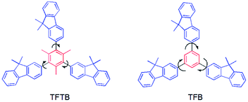
We want to know if the fluorescence of the AIE luminogens can be enhanced to some extent when a large sterically hindered group blocks the aromatic rotor. For this, we prepared a new large sterically hindered fluorene-substituted methylbenzene (1,3,5-tris(9,9-dimethylfluoren-2-yl)-2,4,6-trimethylbenzene) (TFTB) and compared its luminescence properties with fluorene-substituted benzene without large sterically hindered groups (1,3,5-tris(9,9-dimethylfluoren-2-yl)benzene)38,39 (TFB) (Chart 1).
Experimental
Chemicals and instruments
Mesitylene, 2-bromo-9,9-dimethylfluorene and all other chemicals and reagents were purchased from Aladdin Industrial Corporation. THF was distilled under dry nitrogen immediately prior to use. 1H and 13C NMR spectra were measured on a Bruker AV 500 spectrometer in deuterated chloroform or dichloromethane using tetramethylsilane (TMS; δ = 0) as the internal reference. UV-Vis spectra were measured on a JASCO V-570 spectrophotometer. Photoluminescence was recorded on a JASCO FP-6500 spectrophotometer. Thermal transitions were investigated by differential scanning calorimetry using a STA 449 F3 under dry nitrogen at a heating rate of 10 °C min−1. High resolution mass spectrometry was measured on a LTQ-Orbitrap XL high resolution mass spectrometer. X-ray diffraction patterns were recorded on a D8 Advance powder diffractometer using the monochromatized X-ray beam from a nickel-filtered Cu Kα radiation (λ = 1.54183 Å).Aggregation-induced emission investigation
Stock THF solutions of the luminogens with a concentration of 100 μM were prepared. Aliquots of the stock solution were transferred to 10 mL volumetric flasks. After appropriate amounts of THF were added, water was added dropwise under vigorous stirring to furnish 10 μM solutions with different water contents. The PL measurements of the resultant solutions were then performed immediately.Synthetic details
![[thin space (1/6-em)]](https://www.rsc.org/images/entities/char_2009.gif) :
:![[thin space (1/6-em)]](https://www.rsc.org/images/entities/char_2009.gif) 4, v/v); then, it was recrystallized from hexane to give 1,3,5-tris(4,4,5,5-tetramethyl-1,3,2-dioxaborolan-2-yl)-2,4,6-trimethylbenzene, which was a colorless transparent solid (2.40 g, 80%). 1H NMR (500 MHz, CDCl3), δ (TMS, ppm): 2.39 (s, 9H), 1.34 (s, 36H). 13C NMR (125 MHz, CDCl3), δ (TMS, ppm): 147.02, 84.71, 26.38, 23.99. HRMS: m/z 498.3495 (M+, calcd 498.0756).
4, v/v); then, it was recrystallized from hexane to give 1,3,5-tris(4,4,5,5-tetramethyl-1,3,2-dioxaborolan-2-yl)-2,4,6-trimethylbenzene, which was a colorless transparent solid (2.40 g, 80%). 1H NMR (500 MHz, CDCl3), δ (TMS, ppm): 2.39 (s, 9H), 1.34 (s, 36H). 13C NMR (125 MHz, CDCl3), δ (TMS, ppm): 147.02, 84.71, 26.38, 23.99. HRMS: m/z 498.3495 (M+, calcd 498.0756).![[thin space (1/6-em)]](https://www.rsc.org/images/entities/char_2009.gif) :
:![[thin space (1/6-em)]](https://www.rsc.org/images/entities/char_2009.gif) 5, v/v); then, the solvent was removed to give 1,3,5-tris(9,9-dimethylfluoren-2-yl)-2,4,6-trimethylbenzene (TFTB), a white solid (0.21 g, 14%).
5, v/v); then, the solvent was removed to give 1,3,5-tris(9,9-dimethylfluoren-2-yl)-2,4,6-trimethylbenzene (TFTB), a white solid (0.21 g, 14%).![[thin space (1/6-em)]](https://www.rsc.org/images/entities/char_2009.gif) :
:![[thin space (1/6-em)]](https://www.rsc.org/images/entities/char_2009.gif) 5, v/v); then, the solvent was removed to give 1,3,5-tris(9,9-dimethylfluoren-2-yl)-2,4,6-trimethylbenzene (TFTB), a white solid (0.71 g, 51%). 1H NMR (500 MHz, CDCl3), δ (TMS, ppm): 7.79 (d, J = 7.8 Hz, 3H), 7.75 (d, J = 6.7 Hz, 3H), 7.69 (d, J = 1.4 Hz, 3H), 7.63 (dd, J = 7.8, 1.7 Hz, 3H), 7.45 (d, J = 6.3 Hz, 3H), 7.37–7.30 (m, 6H), 3.00 (s, 9H), 1.56 (s, 18H). 13C NMR (125 MHz, CDCl3), δ (TMS, ppm): 155.73, 155.35, 145.57, 142.28, 140.35, 139.82, 128.66, 128.46, 127.73, 124.04, 122.84, 121.71, 121.49, 102.60, 48.42, 40.98, 28.72. HRMS: m/z 696.3756 (M+, calcd 696.9589).
5, v/v); then, the solvent was removed to give 1,3,5-tris(9,9-dimethylfluoren-2-yl)-2,4,6-trimethylbenzene (TFTB), a white solid (0.71 g, 51%). 1H NMR (500 MHz, CDCl3), δ (TMS, ppm): 7.79 (d, J = 7.8 Hz, 3H), 7.75 (d, J = 6.7 Hz, 3H), 7.69 (d, J = 1.4 Hz, 3H), 7.63 (dd, J = 7.8, 1.7 Hz, 3H), 7.45 (d, J = 6.3 Hz, 3H), 7.37–7.30 (m, 6H), 3.00 (s, 9H), 1.56 (s, 18H). 13C NMR (125 MHz, CDCl3), δ (TMS, ppm): 155.73, 155.35, 145.57, 142.28, 140.35, 139.82, 128.66, 128.46, 127.73, 124.04, 122.84, 121.71, 121.49, 102.60, 48.42, 40.98, 28.72. HRMS: m/z 696.3756 (M+, calcd 696.9589).![[thin space (1/6-em)]](https://www.rsc.org/images/entities/char_2009.gif) :
:![[thin space (1/6-em)]](https://www.rsc.org/images/entities/char_2009.gif) 20, v/v); then, it was recrystallized from hexane to give 2-(9,9-dimethylfluoren-2-yl)-4,4,5,5-tetramethyl-1,3,2-dioxaborolane, a colorless transparent solid (4.40 g, 75%). 1H NMR (500 MHz, CDCl3), δ (TMS, ppm): 7.88 (s, 1H), 7.81 (d, J = 7.5 Hz, 1H), 7.74 (dd, J = 12.1, 5.7 Hz, 2H), 7.45–7.41 (m, 1H), 7.35–7.30 (m, 2H), 1.50 (s, 6H), 1.38 (s, 12H). 13C NMR (125 MHz, CDCl3), δ (TMS, ppm): 154.32, 154.12, 153.70, 152.77, 142.21, 141.27, 140.39, 139.20, 138.99, 137.48, 133.49, 128.77, 128.08, 127.75, 126.97, 123.82, 122.64, 120.44, 119.88, 119.34, 83.75, 46.87, 27.08, 24.93, 19.62.
20, v/v); then, it was recrystallized from hexane to give 2-(9,9-dimethylfluoren-2-yl)-4,4,5,5-tetramethyl-1,3,2-dioxaborolane, a colorless transparent solid (4.40 g, 75%). 1H NMR (500 MHz, CDCl3), δ (TMS, ppm): 7.88 (s, 1H), 7.81 (d, J = 7.5 Hz, 1H), 7.74 (dd, J = 12.1, 5.7 Hz, 2H), 7.45–7.41 (m, 1H), 7.35–7.30 (m, 2H), 1.50 (s, 6H), 1.38 (s, 12H). 13C NMR (125 MHz, CDCl3), δ (TMS, ppm): 154.32, 154.12, 153.70, 152.77, 142.21, 141.27, 140.39, 139.20, 138.99, 137.48, 133.49, 128.77, 128.08, 127.75, 126.97, 123.82, 122.64, 120.44, 119.88, 119.34, 83.75, 46.87, 27.08, 24.93, 19.62.![[thin space (1/6-em)]](https://www.rsc.org/images/entities/char_2009.gif) :
:![[thin space (1/6-em)]](https://www.rsc.org/images/entities/char_2009.gif) 5, v/v); then, the solvent was removed to give 1,3,5-tris(9,9-dimethylfluoren-2-yl)benzene (TFB), a white solid (1.52 g, 73%). 1H NMR (500 MHz, CDCl3), δ (TMS, ppm): 7.89 (s, 3H), 7.85 (d, J = 7.8 Hz, 3H), 7.78 (dd, J = 6.3, 1.2 Hz, 6H), 7.73 (dd, J = 7.8, 1.6 Hz, 3H), 7.47 (dd, J = 6.3, 1.2 Hz, 3H), 7.39–7.32 (m, 6H), 1.57 (s, 18H). 13C NMR (125 MHz, CDCl3), δ (TMS, ppm): 154.42, 153.97, 142.97, 140.55, 138.84, 127.37, 127.08, 126.54, 125.37, 122.66, 121.78, 120.38, 120.15, 47.07, 27.29. HRMS: m/z 654.3287 (M+, calcd 654.8792).
5, v/v); then, the solvent was removed to give 1,3,5-tris(9,9-dimethylfluoren-2-yl)benzene (TFB), a white solid (1.52 g, 73%). 1H NMR (500 MHz, CDCl3), δ (TMS, ppm): 7.89 (s, 3H), 7.85 (d, J = 7.8 Hz, 3H), 7.78 (dd, J = 6.3, 1.2 Hz, 6H), 7.73 (dd, J = 7.8, 1.6 Hz, 3H), 7.47 (dd, J = 6.3, 1.2 Hz, 3H), 7.39–7.32 (m, 6H), 1.57 (s, 18H). 13C NMR (125 MHz, CDCl3), δ (TMS, ppm): 154.42, 153.97, 142.97, 140.55, 138.84, 127.37, 127.08, 126.54, 125.37, 122.66, 121.78, 120.38, 120.15, 47.07, 27.29. HRMS: m/z 654.3287 (M+, calcd 654.8792).Results and discussion
Synthetic strategy
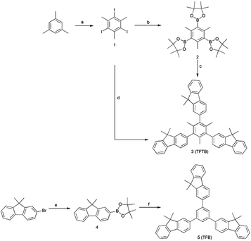
The compound TFTB was prepared by a Suzuki coupling reaction,40 which was carried out using an aryl boronate in the presence of a base and a Pd (0) catalyst (Scheme 1). The first synthesized 1,3,5-tris(4,4,5,5-tetramethyl-1,3,2-dioxaborolan-2-yl)-2,4,6-trimethylbenzene and 2-bromo-9,9-dimethylfluorene can be used as the substrate.41–43 It is also possible to use 1,3,5-triiodo-2,4,6-trimethylbenzene and 2-(9,9-dimethylfluoren-2-yl)-4,4,5,5-tetramethyl-1,3,2-dioxaborolane as substrates, and the target compounds can be obtained by both methods. However, the second method resulted in a higher yield (51%) due to the steric hindrance of the reaction. Their spectra can be found in the ESI.† Its powder was crystalline, as revealed by the X-ray diffractogram (Fig. S1†). All luminescent agents are soluble in common organic solvents such as tetrahydrofuran (THF), but insoluble in water.Aggregation-induced emission (AIE) property
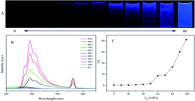
To test if TFTB is AIE active, we added water to its THF solution and recorded its PL spectrum in the water-THF mixture (Fig. 1). When the water fraction (fw, vol%) in the water–THF mixture was less than 50%, its PL emission remained in a very weak state with only a slight change. When a large amount of water (fw ≥ 60%) was added, a long-wavelength emission with a peak at 394 nm appeared, and the intensity was greatly enhanced. The emission peak red-shifted compared to that of its THF solution and the frequency-doubled peak appeared at 561 nm. TFTB is insoluble in water, and an increase in water content causes the TFTB molecules to assume an aggregated state. The formation of aggregates greatly weakens the intramolecular rotation (IMR) process, causing the luminogens to emit intense fluorescence. A similar emission behavior of TFB was also observed in the water–THF mixture (Fig. S2†), confirming that it is also AIE active.Computational research, photophysical properties
The molecular conformation was optimized by the semi-empirical PM3 method (Fig. 2). The fluorene unit was arranged in a star-shaped propeller shape. The highly twisted conformation of the TFTB results in a poor electronic communication between the rotor and the stator and little orbital overlap. Molecular orbital amplitude maps of the LUMO and HOMO levels of the two molecules (Fig. S3†) show that they were clearly dominated by the orbits of the fluorene rings of the surrounding rotors. This indicates that the emission of TFTB is derived from the excited state of the rotor fluorene ring around it. Among them, the three fluorene rings of TFTB contribute to the LUMO and HOMO energy levels. However, there is a ring that does not contribute to its HOMO level at all in TFB.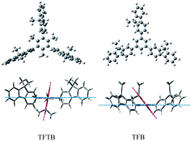 | ||
| Fig. 2 Optimized molecular structures of TFTB and TFB calculated by a semi-empirical PM3 method. (The blue line represents the benzene ring plane; the red line represents the fluorene ring plane.) | ||
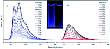
TFTB shows the maximum absorption at 328 nm (Fig. S4†), and its energy band gap is calculated to be 4.77 eV (Fig. S5†). TFB shows the maximum absorption at 336 nm, and its energy band gap is calculated to be 4.32 eV. Since there is a fluorene ring in TFB that does not contribute to its HOMO level, this is also the reason why the energy band gap of TFTB is wider than that of TFB. This is in good agreement with the blue-shift of the absorption spectrum of TFTB in the THF solution. The structural difference between TFTB and TFB is that the former has three methyl groups on the stator. Following our hypothesis, it is clear that the hindrance of these three methyl groups restricts the rotation of the rotor, so that TFTB emits in the solution state, while TFB has only weak luminescence in the solution state. The gradually thickened TFTB and TFB in the THF solution (from 1 μM to 100 μM) only increase their emission intensities, and hardly affect their spectral distribution and peak position. TFTB has two peaks at 362 nm and 380 nm, while TFB has only one peak, which appears at 368 nm (Fig. 3). This is because the methyl group inside the TFTB molecule in the solution state hinders the IMR process of its luminescent rotor, causing its various portions to emit characteristic peaks. However, due to the IMR process, TFB loses energy between the rotor and the stator; the exciton radiation is attenuated, and the emission peaks of each part are mixed.
TFTB and TFB can also fluoresce in the solid state (Fig. 4A and C). Their solids show PL emission characteristics. The PL spectrum of the TFTB solid exhibits a peak at 424 nm (Fig. 4B). Its quantum yield is 37.44%. Its solid has very good fluorescence under UV light. The PL spectrum of the TFB solid exhibits a peak at 380 nm. Its quantum yield is 21.36%. However, the fluorescence of the solid under UV light is inferior to that of TFTB because the twisted conformation of TFTB makes it less prone to π-stacking. The TFB's fluorene rings can partially overlap in the solid state, resulting in strong intermolecular interactions, thereby reducing the emission efficiency. This is also confirmed from the Tg = 328 °C of TFB, which is greater than the Tg = 282 °C of TFTB (Fig. S6†), indicating that the TFB intermolecular interaction is stronger than TFTB. The above evidence demonstrates that restricting the intramolecular rotation can produce strong fluorescence emissions.
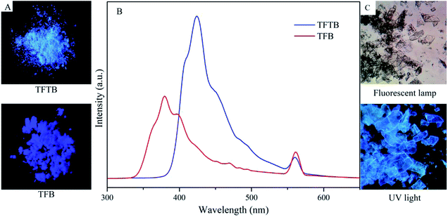 | ||
| Fig. 4 (A) Photos of the solid under UV light. (B) Solid PL spectra of TFTB and TFB. (C) Photomicrograph of the TFTB solid. | ||
Potential energy surface scan
To further verify that the presence of methyl groups on the stator does hinder the rotation of the rotor, we calculated the total energy of the two molecular systems as a function of the angle between the fluorene ring plane and the benzene ring plane, as shown in the potential energy surface scan (Fig. 5). When the angle between the fluorene ring plane and the benzene ring plane of TFTB was 99.76°, the total energy of the entire molecular system was the lowest. When the angle was 189.76°, the fluorene ring was closest to the methyl group, and the total energy of the entire molecular system was the highest. When the TFB's fluorene-benzene dihedral angle was −38.03°, the total energy of the system was the lowest. When the angle was 81.97°, the total energy of the system was the highest. When both energies were highest, the energy of TFTB was much larger than that of TFB. However, after one revolution, the total energy of the TFTB system was not the same as the initial energy because the fluorene ring itself did not have a symmetrical structure. The methyl group was not evenly extruded on the fluorene ring. This is not the case with TFB. Collectively, these results verified that the methyl group on the stator could restrict the rotation of the rotor.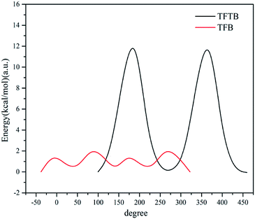 | ||
| Fig. 5 The total energy of the system varies with the angle between the fluorene ring plane and the benzene ring plane. | ||
Conclusions
In summary, a new AIE-active large sterically hindered fluorene-benzene copolymer TFTB and a new phenyl boronate intermediate were synthesized. By comparing the fluorescence properties of TFTB with those of the control compound TFB and from the theoretical calculation data, it was confirmed that the groups present on the stator could hinder the rotation of the fluorescent rotor and deactivate the IMR process, enhancing the fluorescence emission in solids and solutions. The properties of TFTB examined in this work provide a new strategy for synthesizing AIE luminogens with a distorted conformation.Conflicts of interest
There are no conflicts to declare.Acknowledgements
We thank the State Key Laboratory of Fine Chemicals of Dalian University of Technology for providing us with support on high-resolution mass spectrometer.Notes and references
- Y. Hong, J. W. Y. Lam and B. Z. Tang, Chem. Commun., 2009, 0, 4332 RSC.
- Y. Hong, J. W. Y. Lam and B. Z. Tang, Chem. Soc. Rev., 2011, 40, 5361 RSC.
- C. L. Tao, B. Chen, X. G. Liu, L. J. Zhou, X. L. Zhu, J. Cao, Z. G. Gu, Z. J. Zhao, L. Shena and B. Z. Tang, Chem. Commun., 2017, 53, 9975 RSC.
- Z. M. Wang, F. Zhou, C. Gui, J. Wang, Z. J. Zhao, A. J. Qina and B. Z. Tang, J. Mater. Chem. C, 2018, 6, 11261 RSC.
- Z. Zhao, J. W. Y. Lam and B. Z. Tang, J. Mater. Chem., 2012, 22, 23726 RSC.
- T. T. Kong, Z. Zhao, Y. Li, F. Wu, T. Jin and B. Z. Tang, J. Mater. Chem. B, 2018, 6, 5986 RSC.
- Y. L. Wang, C. Fan, B. Xin, J. P. Zhang, T. Luo, Z. Q. Chen, Q. Y. Zhou, Q. Yu, X. N. Li, Z. L. Huang, C. Li, M. Q. Zhu and B. Z. Tang, Mater. Chem. Front., 2018, 2, 1554 RSC.
- J. Yang, J. Huang, Q. Li and Z. Li, J. Mater. Chem. C, 2016, 4, 2663 RSC.
- A. C. Sedgwick, L. L. Wu, H. H. Han, S. D. Bull, X. P. He, T. D. James, J. L. Sessler, B. Z. Tang, H. Tian and J. Yoon, Chem. Soc. Rev., 2018, 47, 8842 RSC.
- W. W. H. Lee, Z. Zhao, Y. J. Cai, Z. Xu, Y. Yu, Y. Xiong, R. T. K. Kwok, Y. Chen, N. L. C. Leung, D. Ma, J. W. Y. Lam, A. J. Qin and B. Z. Tang, Chem. Sci., 2018, 9, 6118 RSC.
- D. Ding, K. Li, B. Liu and B. Z. Tang, Acc. Chem. Res., 2013, 46, 2441 CrossRef CAS PubMed.
- Z. Zhuang, P. C. Shen, S. Y. Ding, W. W. Luo, B. R. He, H. Nie, B. H. Wang, T. B. Huang, R. R. Hu, A. J. Qin, Z. J. Zhao and B. Z. Tang, Chem. Commun., 2016, 52, 10842 RSC.
- J. Liang, B. Z. Tang and B. Liu, Chem. Soc. Rev., 2015, 44, 2798 RSC.
- X. Zhang, X. Zhang, L. Tao, Z. Chi, J. Xu and Y. Wei, J. Mater. Chem. B, 2014, 2, 4398 RSC.
- J. Z. Liu, J. W. Y. Lam and B. Z. Tang, Chem. Rev., 2009, 109, 5799 CrossRef CAS PubMed.
- Q. Wan, Q. Huang, M. Y. Liu, D. Z. Xu, H. Y. Huang, X. Y. Zhang and Y. Wei, Appl. Mater. Today, 2019, 9, 145 CrossRef.
- X. Y. Zhang, K. Wang, M. Y. Liu, X. Q. Zhang, L. Tao, Y. W. Chen and Y. Wei, Nanoscale, 2015, 7, 11486 RSC.
- X. Y. Zhang, X. Q. Zhang, B. Yang, M. Y. Liu, W. Y. Liu, Y. W. Chen and Y. Wei, Polym. Chem., 2014, 5, 356 RSC.
- X. Y. Zhang, X. Q. Zhang, B. Yang, M. Y. Liu, W. Y. Liu, Y. W. Chen and Y. Wei, Polym. Chem., 2014, 5, 399 RSC.
- Z. Long, M. Y. Liu, R. M. Jiang, Q. Wan, L. C. Mao, Y. Q. Wan, F. J. Deng, X. Y. Zhang and Y. Wei, Chem. Eng. J., 2016, 308, 527 CrossRef.
- Z. Long, L. C. Mao, M. Y. Liu, Q. Wan, Y. Q. Wan, X. Y. Zhang and Y. Wei, Polym. Chem., 2017, 8, 5644 RSC.
- Z. Long, M. Y. Liu, K. Wang, F. J. Deng, D. Z. Xu, L. J. Liu, Y. Q. Wan, X. Y. Zhang and Y. Wei, Mater. Sci. Eng. C, 2016, 66, 215 CrossRef CAS PubMed.
- L. Huang, S. J. Yang, J. Y. Chen, J. W. Tian, Q. Huang, H. Y. Huang, Y. Q. Wen, F. J. Deng, X. Y. Zhang and Y. Wei, Mater. Sci. Eng., C, 2018, 94, 270 CrossRef PubMed.
- R. M. Jiang, M. Y. Liu, H. Y. Huang, L. C. Mao, Q. Huang, Y. Q. Wen, Q. Y. Cao, J. W. Tian, X. Y. Zhang and Y. Wei, J. Colloid Interface Sci., 2018, 519, 137 CrossRef CAS PubMed.
- J. Y. Chen, M. Y. Liu, Q. Huang, L. Huang, H. Y. Huang, F. J. Deng, Y. Q. Wen, J. W. Tian, X. Y. Zhang and Y. Wei, Chem. Eng. J., 2018, 337, 82 CrossRef CAS.
- W. H. Xu, M. M. S. Lee, Z. H. Zhang, H. H. Y. Sung, L. D. Williams, R. T. K. Kwok, J. W. Y. Lam, D. Wang and B. Z. Tang, Chem. Sci., 2019, 10, 3494 RSC.
- J. Mei, N. Leung, R. Kwok, J. W. Y. Lam and B. Z. Tang, Chem. Rev., 2015, 115, 11718 CrossRef CAS PubMed.
- J. Mei, Y. Hong, J. W. Y. Lam, A. Qin, Y. Tang and B. Z. Tang, Adv. Mater., 2014, 26, 5429 CrossRef CAS PubMed.
- N. L. Leung, N. Xie, W. Yuan, Y. Liu, Q. Wu, Q. Peng, Q. Miao, J. W. Y. Lam and B. Z. Tang, Chem.–Eur. J., 2014, 20, 15349 CrossRef CAS.
- F. Bu, E. Wang, Q. Peng, R. Hu, A. Qin, Z. Zhao and B. Z. Tang, Chem.–Eur. J., 2015, 21, 4440 CrossRef CAS PubMed.
- H. Nie, K. Hu, Y. J. Cai, Q. Peng, Z. J. Zhao, R. R. Hu, J. W. Chen, S. J. Su, A. J. Qin and B. Z. Tang, Mater. Chem. Front., 2017, 1, 1125 RSC.
- J. J. Guo, S. M. Hu, W. W. Luo, R. R. Hu, A. J. Qin, Z. J. Zhao and B. Z. Tang, Chem. Commun., 2017, 53, 1463 RSC.
- H. T. Feng, Y. X. Yuan, J. B. Xiong, Y. S. Zheng and B. Z. Tang, Chem. Soc. Rev., 2018, 47, 7452 RSC.
- J. Zhou, Z. F. Chang, Y. B. Jiang, B. R. He, M. Du, P. Lu, Y. N. Hong, H. S. Kwok, A. J. Qin, H. Y. Qiu, Z. J. Zhao and B. Z. Tang, Chem. Commun., 2013, 49, 2491 RSC.
- J. Q. Shi, N. Chang, C. H. Li, J. Mei, C. M. Deng, X. L. Luo, Z. P. Liu, Z. S. Bo, Y. Q. Dong and B. Z. Tang, Chem. Commun., 2012, 48, 10675 RSC.
- Z. Y. Yang, Z. H. Chi, Z. Mao, Y. Zhang, S. W. Liu, J. Zhao, M. P. Aldred and Z. G. Chi, Mater. Chem. Front., 2018, 2, 861–890 RSC.
- X. H. Zhou, J. C. Yan and J. Pei, Org. Lett., 2003, 5, 3543 CrossRef CAS PubMed.
- K. Okumoto and Y. Shirota, Chem. Mater., 2003, 15, 699 CrossRef CAS.
- B. Wang, X. L. Lv, D. W. Feng, L. H. Xie, J. Zhang, M. Li, Y. B. Xie, J. R. Li and H. C. Zhou, J. Am. Chem. Soc., 2016, 138, 6204 CrossRef CAS PubMed.
- T. Ishiyama, M. Murata and N. Miyaura, J. Org. Chem., 1995, 60, 7508 CrossRef CAS.
- F. S. Han, Chem. Soc. Rev., 2013, 42, 5270 RSC.
- A. S. Castanet, F. Colobert, P. E. Broutin and M. Obringer, Tetrahedron: Asymmetry, 2002, 13, 659 CrossRef CAS.
- L. Grimaud and A. Jutand, Synthesis, 2017, 49, 1182 CAS.
Footnote |
| † Electronic supplementary information (ESI) available: 1H and 13C NMR spectra and additional figures. See DOI: 10.1039/c9ra01636h |
| This journal is © The Royal Society of Chemistry 2019 |

