 Open Access Article
A photoelectrochemical glucose sensor based on gold nanoparticles as a mimic enzyme of glucose oxidase†
Ling Cao,
Panpan Wang,
Li Chen,
Ying Wu and
Junwei Di *
*
College of Chemistry, Chemical Engineering and Material Science, Soochow University, Suzhou, 215123, PR China. E-mail: 20164209007@stu.suda.edu.cn; 985604192@qq.com; 1610796834@qq.com; yingwu@suda.edu.cn; djw@suda.edu.cn
First published on 16th May 2019
Abstract
This work reports the first construction of the ternary layers of ITO/PbS/SiO2/AuNPs nanostructure for development of photoelectrochemical (PEC) glucose sensor. Herein, the thioglycolic acid-capped PbS quantum dots was employed as a PEC active probe, which is very sensitive to oxygen. The small gold nanoparticles (AuNPs) were act as nanozyme (mimic enzyme of glucose oxidase) to catalytically oxidize glucose in the presence of oxygen, meanwhile consumed oxygen and then resulted in the decrease of cathodic photocurrent. The insertion layer of SiO2 nanoparticles between PbS and AuNPs could reduce efficiently the base current due to its low electroconductivity, which improved the detection limit. The proposed PEC sensor exhibited high sensitivity and gold selectivity towards glucose. The linear response of glucose concentrations ranged from 1.0 μM to 1.0 mM with detection limit of 0.46 μM (S/N = 3). The results suggest the potential of design and development of numerous nanozyme-based PEC biosensors with the advantage of the simplicity, stability, and efficiency.
Introduction
Glucose, as the main energy source of the human body, plays an important role in various life processes. It is especially important for patients with diabetes to judge whether the metabolism of sugar is normal.1,2 Due to the high demand for blood glucose detection, a lot of work has been devoted to the production of reliable glucose sensors.3 In recent years, many methods have been developed for glucose detection, such as spectrophotometry,4–6 electrochemical methods,7–9 photoelectric chemiluminescence methods,10–12 surface enhanced Raman spectroscopy,13–15 fluorescence spectroscopy16–18 and photoelectrochemical (PEC) methods.19–22 Among them, PEC measurement methods have attracted wide attention because of their simple equipment, low cost, quick response, high sensitivity and good selectivity.Enzyme is an efficient, highly active and substrate specific catalyst. It has important significance in biosensor, pharmaceutical process, food industry, and industrial and agricultural chemical production.23 For example, in the presence of oxygen, glucose oxidase (GOD) can catalytically oxidize glucose to generate gluconic acid and hydrogen peroxide. Since the first enzyme electrode was reported in 1962,24 more and more efforts have been made to develop a fast, simple, sensitive and reliable glucose detection method.25 However, the disadvantages, such as the degeneration and digestion of enzymes, the sensitivity of catalytic activity to environmental conditions, the difficulty in recovery and the high cost, have greatly restricted the application of natural enzyme.23
Recently, enzyme-mimetic nanomaterials (nanozymes) have been attracted greatly due to their simple preparation, low cost, and high stability.26 Because of the characteristics of simple preparation, good biocompatibility and unique photoelectron performance, gold nanoparticles (AuNPs) have attracted more and more attention in many fields.27 Moreover, small AuNPs were demonstrated to have catalytic properties similar to GOD.28,29 In the presence of oxygen, they can catalytically oxidize glucose to produce gluconic acid and hydrogen peroxide. This catalytic reaction has been employed to detect glucose in colorimetry.30,31
Herein, a new PEC sensor was constructed for detection of glucose. The PEC biosensor was prepared with multi-layer PbS quantum dots (PbS QDs) on the indium tin oxide (ITO) electrode surface, which led efficient photocurrent response. Small AuNPs was used as mimic enzyme of GOD, catalyzing the glucose oxidation to gluconic acid with consuming oxygen in situ. The insulated SiO2 nanospheres (SiO2 NSs) were inserted between the layers of PbS and AuNPs, which could efficiently reduce the base current and improve the detection limit. It is demonstrated that this nanozyme-based biosensor can be successfully used in the PEC detection of glucose, substituting for nature enzyme.
Experimental section
Reagents and apparatus
Pb(NO3)2, tetraethyl orthosilicate (TEOS), (3-mercaptopropyl)-trimethoxysilane, NH3·H2O, ethanol, trisodium citrate dehydrate (C6H5Na3O7·2H2O), tetrachloroauric acid (HAuCl4·4H2O), tris-(hydroxymethyl)aminomethane (Tris–HCl), sodium hydroxide and D-(+)-glucose were purchased from Sinopharm Chemical Reagent Co., Ltd. (China). Thioglycolic acid (TGA) was purchased from Acros Organics. Poly-(diallyldimethylammonium chloride) (PDDA), Na2S·9H2O, sodium borohydride (NaHB4, 98%)were purchased from Aladdin Chemical Reagent Co. Ltd. ITO thin film coated glass (1.1 mm, ∼100 Ω □−1) was purchased from Suzhou SNSG Electronics Co. Ltd. The ITO substrates (50 × 10 mm) were cleaned in dilute ammonia water, ethanol and ultrapure water with ultrasonication, followed by drying with N2. All solutions were prepared with ultrapure water (18.2 MΩ cm).Transmission electron microscopy (TEM) image was obtained on a Tecnai G20 transmission electron microscope (FEI, U.S.A). Scanning electron microscopy (SEM) was performed using S-4700 SEM (Hitachi, Japan). The phase structure of the sample was measured by X-ray powder diffraction (XRD) on MiniFlex 300/600 XRD (Japan). X-ray photoelectron spectroscopy (XPS) was obtained from ESCALAB220i-XL. Photocurrent was measured on a RST5200 electrochemical workstation (Suzhou Risetest Electronic Co., Ltd., China). A PbS/SiO2/AuNPs (the surface area is 0.25 cm2) modified ITO electrode was employed as the working electrode. A Pt wire was used as the counter electrode, and a saturated calomel electrode (SCE) as the reference electrode. A LED lamp with the wavelength of 470 nm was used as irradiation source (Brillante, TianJin, China).
Synthesis of TGA-stabilized PbS QDs
TGA-capped PbS QDs were synthesized in aqueous solution using a slightly modified procedure.32 Firstly, 0.16 mmol of lead acetate trihydrate was dissolved in 50 mL of ultrapure water, and the air in the solution was removed with N2 gas for 30 min. Then 50 μL TGA was dropped into the flask under strong magnetic stirring. The pH value of the solution was adjusted to 11.0 with 1 mol L−1 NaOH. Next, the solution of Na2S (4 mL, 0.015 mol L−1) without oxygen was slowly injected into the solution. Immediately, the solution turned from colorless to dark-brown. The reaction mixture was stirred under a N2 atmosphere for 3 h. The as-synthesized TGA-capped PbS QDs were stored at 4 °C.Synthesis of thiol-modified SiO2 NSs
The utilized SiO2 were synthesized according to the previous report.33 By adding 1 mL TEOS in a mixture of ethanol (35.7 mL), water (5 mL) and ammonia (0.8 mL), SiO2 NSs were synthesized. After stirring for 24 h at 30 °C, the product was rinsed by water and ethanol, and then dissolved in 10 mL ethanol. The above solution were treated with 50 μL (3-mercaptopropyl)trimethoxysilane and stirred for 24 h at 30 °C to obtain thiol-groups modified SiO2 NSs.Synthesis of small AuNPs
AuNPs were synthesized in aqueous solution according to our previously reported work.34 Firstly, 0.5 mL HAuCl4 (10 mM), 0.5 mL C6H5Na3O7·2H2O (10 mM) aqueous solution and 19 mL ultrapure water were mixed at room temperature. Then, 0.5 mL freshly prepared NaHB4 (0.1 mM) was added to the solution under stirring. The solution became orange red immediately. Further stirring about 5–10 min, the gold nanoparticles solution was stable and stored in a refrigerator at 4 °C for future use.Fabrication of the ITO/PbS/SiO2/AuNPs electrode
The modification of PbS QDs on ITO electrode was according to previously reported methods based on the electrostatic interaction between positively charged PDDA and negatively charged TGA-capped PbS QDs. The ITO/PbS electrodes (10 × 10 mm) were fabricated by being alternately immersed into a solution of 2% aqueous PDDA containing 0.5 M NaCl and the TGA-capped PbS QDs solution for 10 minutes. For each step, the surfaces of electrodes were washed with ultrapure water and dried with nitrogen. The process was repeated by dipping in PDDA and PbS QDs solutions to obtain multilayers of PbS QDs modified electrodes. Next, 50 μL thiol-modified SiO2 NSs were added onto the PbS-modified ITO electrode, and dried naturally. Blowing off the unsound SiO2 NSs, 50 μL gold nanoparticles solution was dropped onto the ITO/PbS/SiO2 electrode and then dried in an oven at 50 °C. The prepared electrode was defined as ITO/PbS/SiO2/AuNPs electrode.Photoelectrochemical detection of glucose
For glucose detection, the ITO/PbS/SiO2/AuNPs electrode was immersed in 10 mL of 0.1 M Tris–HCl buffer (pH 7.4) with passing into oxygen gas for 5 minutes. The blank photocurrent was recorded. Then 100 μL of certain concentration of glucose was added into the solution for the photocurrent measurements at room temperature. The decrease of the photocurrent intensity was employed for quantitative detection of glucose. To detect glucose in real samples, the diluted serum sample (the real samples were obtained from local hospital) was measured by the same procedure.Results and discussion
Morphological and structural characterization
TEM and XRD were utilized to reveal morphological and structural information about the samples. Fig. S1† shows the TEM image of the as-synthesized TGA-capped PbS QDs, thiol-modified SiO2 NSs and small AuNPs, which appeared as quasi-spherical particles with average size of ∼5 nm, ∼50 nm, and ∼4 nm, respectively. Fig. S2† displayed the XRD pattern of the as-fabricated PbS QDs, thiol-modified SiO2 and gold nanoparticles. The XRD pattern of the PbS QDs exhibits sharp prominent peaks at scattering angles (2θ) of 25.89°, 30.02°, 43.16°, 50.89°, 53.21°, 62.49°, 68.81°, 71.96°, and 78.87°, indexed to scattering from the (111), (200), (220), (311), (222), (400), (331), (420), and (422) planes, respectively, of the standard cubic PbS (JCPDS card no. 5-592). This pattern indicated that the sample was face-centered cubic PbS. The second pattern indicated that the as-synthesized SiO2 was amorphous structure with characteristic peaks at 2θ values of 22.9° (JCPDS card no. 29-0085). The third pattern of the Au would indexed all the observed peaks to the face-centered cubic Au, with characteristic peaks of the Au at 2θ values of 38.26°, 44.67°, 64.81°, and 77.53° corresponding to the (111), (200), (220), and (311) crystal planes, respectively, of cubic Au (JCPDS card no. 04-0784). All of these verified the successful synthesis of PbS QDs, thiol-modified SiO2 and gold nanoparticles.Characterization of ITO/PbS/SiO2/AuNPs electrode
Fig. 1a shows the SEM image of PbS QDs deposited onto the ITO surface. It can be seen that the majority of PbS particles are uniformly distributed on the ITO glass with a small amount of aggregation. Further assembly of SiO2 NSs on the ITO glass (Fig. 1b), the spheroidal SiO2 particles were coated on the ITO/PbS electrode with size of ∼50 nm nanoparticles on the electrode surface, indicating that the SiO2 particles were successfully assembled onto the PbS surface. Finally, the AuNPs were assembled to the surface of electrode (Fig. 1c). It can be seen from the inset figure that some small gold nanoparticles were distributed around the large SiO2 nanoparticles, indicating that AuNPs was successfully immobilized on the electrode surface. In order to further explore the distribution of PbS, SiO2 and Au on the ITO surface, a mapping analysis was performed on a region of the SEM image. As shown in Fig. 1d, the elements Pb, S, Si, and Au were uniformly distributed on the surface of the electrode, and it was verified that PbS, SiO2, and AuNPs were successfully modified onto the ITO glass.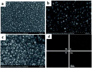 | ||
| Fig. 1 SEM images of (a) ITO/PbS, (b) ITO/PbS/SiO2, (c) ITO/PbS/SiO2/AuNPs electrodes. (d) Elemental mapping of the ITO/PbS/SiO2/AuNPs nanofilm. | ||
XPS was further performed to study the surface chemical compositions and oxidation states of the ITO/PbS/SiO2/AuNPs electrode. The peak positions were determined with a C 1s binding energy of 284.6 eV as the internal marked standard. Fig. 2a depicts the full-scan XPS spectrum of the PbS/SiO2/AuNPs nanofilm with the relevant elements being Pb, S, Si, O, Au and C. The corresponding high-resolution XPS spectra of Pb 4f, S 2p, Si 2p, Au 2p, and O 1s are also illustrated. The peak of C 1s in the graph was due to adventitious hydrocarbons from the instrument. Fig. 2b presents the Pb 4f7/2 and Pb 4f5/2 signal with maxima located at ∼138 eV and ∼143 eV, while Fig. 2c shows the S 2p signal consisted of S 2p1/2 and S 2p3/2 at around 163 eV, which should be assigned to the PbS compound. Fig. 2d of Si 2p exhibits a peak at around 103 eV. Fig. 2e of the O 1s spectrum exhibits a peak at binding energies of ∼532 eV. The peaks at 532 eV can be assigned to O2− in octahedral symmetry (bulk O) associated with SiO2 species. Fig. 2f presents the Au 4f7/2 and Au 4f5/2 signal with maxima located at ∼83 eV and ∼87 eV.
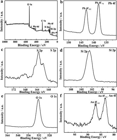 | ||
| Fig. 2 (a) Full-scan XPS spectrum of the as-fabricated PbS/SiO2/AuNPs nanofilm and (b–f) high-resolution XPS spectra of Pb 4f, S 2p, Si 2p, O 1s, and Au 4f, respectively. | ||
It is known that electrochemical impedance spectroscopy (EIS) can provide information on the electron-transfer property of electrode. The assembly process of the electrode can be described by the resistance of the electrode. Fig. 3 shows the EIS of different electrodes using K3Fe(CN)6/K4Fe(CN)6 as an electrochemical probe. When the PbS QDs were assembled on the ITO electrode, the diameter of the semicircle increased due to the semiconductor characteristics of PbS. After SiO2 had further deposited on the ITO/PbS electrode, the electron-transfer resistance further increased because the SiO2 insulator blocked the electron-transfer between the electrochemical probe and electrode. When the AuNPs were assembled on the electrode, the diameter of the semicircle decreased due to the introduction of excellent electrical conductivity of Au. According to the pattern, the resistances of all these electrodes were not particularly big. This implies that the ITO/PbS/SiO2/AuNPs electrode exhibited good electron-transfer property. This further verifies that SiO2 and gold nanoparticles are successfully modified to PbS quantum dots.
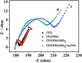 | ||
| Fig. 3 The EIS of (a) bare ITO, (b) ITO/PbS, (c) ITO/PbS/SiO2, and (d) ITO/PbS/SiO2/AuNPs electrode in 5 mM [Fe(CN)6]3−/4− solution. | ||
Photoelectrochemical sensing mechanism
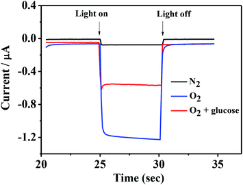
Fig. 4 shows the photocurrent of ITO/PbS/SiO2/AuNPs electrode in 0.1 M Tris–HCl buffer solution (pH = 7.4) with the blue LED light irradiation before and after addition of 1 mM glucose solution. The photocurrent value of the ITO/PbS/SiO2/AuNPs electrode in N2-saturated solution was about 70 nA. While the photocurrent value in the oxygen-containing buffer solution was about 1.2 μA, which indicated that the oxygen in the solution has a great influence on it. It is well known that PbS is a p-type semiconductor with holes as the main carrier. When the PbS QDs absorb the matched energy, the electrons are excited from the valence band (VB) to the conduction band (CB). The photoelectron transfer rate to electrolyte solution is faster than that of hole capture through ITO electrode, resulting in cathode photocurrent generation. Thus PbS is extremely sensitive to oxygen which is act as electron acceptor.35 Furthermore, the photocurrent of the ITO/PbS/SiO2/AuNPs electrode was significantly reduced to about 0.5 μA after addition of 1 mM glucose in the system. The PEC mechanism of glucose response at the ITO/PbS/SiO2/AuNPs electrode is illustrated in Scheme 1. The AuNPs on the electrode surface act as a GOD mimic enzyme. In the presence of O2, AuNPs catalytically oxidize glucose to produce gluconic acid and hydrogen peroxide. Meanwhile, the oxygen is consumed, which decreases the concentration of the electron acceptor on the electrode surface. Therefore, the intensity of the cathode photocurrent decreased as addition of glucose. This is basic for quantitative detection of glucose.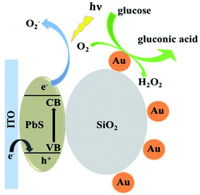 | ||
| Scheme 1 Schematic illustration of the PEC strategy for detection of glucose at ITO/PbS/SiO2/AuNPs electrode. | ||
Effect of the insert layer of SiO2 NSs
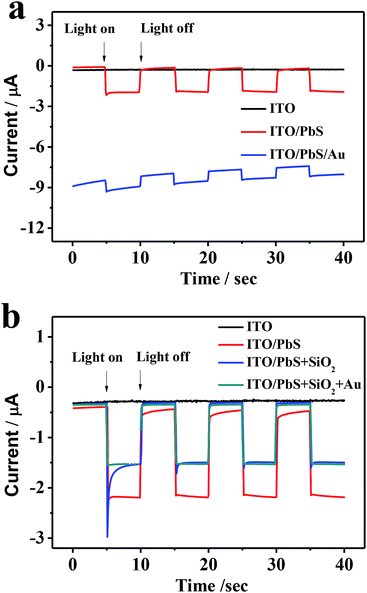
Fig. 5a displays the photocurrent responses at the ITO/PbS electrode and ITO/PbS/AuNPs electrode. The ITO/PbS photoelectrode exhibited a good photocurrent response in the presence of oxygen in the system. The ITO/PbS/AuNPs electrode was prepared by direct assembly of AuNPs on the surface of PbS layer. Comparison with the ITO/PbS electrode, the photocurrent at the ITO/PbS/AuNPs electrode reduced markedly. Especially, the base current of the photoelectrode was very high due to the excellent conductivity of gold, which was unfavorable for quantitative detection. Therefore, we tried to insert SiO2 NSs between the PbS layer and AuNPs. As increasing the addition concentration of SiO2, the base current of the photoelectrode was reducing, but the photocurrent intensity was little change (Fig. S3†). When the addition concentration of SiO2 was 0.22 mol L−1, the base current of the ITO/PbS/SiO2/AuNPs electrode was similar to that of the ITO/PbS electrode. Considering that too thick SiO2 layer may hinder the irradiation of LED lamp and diffusion of oxygen, 0.22 mol L−1 was selected as the optimal concentration of SiO2 in the next experiments. As shown in Fig. 5b, the photocurrent of ITO/PbS/SiO2 electrode was only reduced by about 30% compared with that of ITO/PbS photoelectrode. Furthermore, the photocurrent response of ITO/PbS/SiO2/AuNPs electrode was similar to that of the ITO/PbS/SiO2 electrode, attributing to low conductivity of SiO2 NSs.36 These results demonstrated that the insert layer of SiO2 NSs between PbS QDs and AuNPs could not only maintain most of PEC activity but also efficiently reduce base current.Optimization of experimental conditions
The cathodic photocurrent intensity was dependent on the pH of buffer solution. As shown in Fig. S4a,† the photocurrent response was low when the pH value was below 6.2. The photocurrent intensity increased gradually with the increasing of pH value over 7.4. Considering physiological condition pH value, pH = 7.4 Tris–HCl buffer solution was selected as the supporting electrolyte.The applied potential is another significant factor to the photocurrent response. Fig. S4b† shows that the cathodic photocurrent response increased with negative shift of the applied potential from 0 to −0.2 V, and then reached a plateau. Therefore, an optimal potential of −0.2 V was employed in the next PEC measurements.
PEC detection of glucose
We then applied the developed ITO/PbS/SiO2/AuNPs photoelectrode for glucose determination. Fig. 6a illustrates the photocurrent responses in the presence of variable glucose concentrations at a bias potential of −0.2 V. The photocurrent intensity decreased steadily with the increasing of glucose concentration, reaching a saturation level of 1 mM. The negative correlation between the observed cathodic photocurrent and glucose concentration is due to the competition between the photocathode and the mimic enzyme of AuNPs for dissolved oxygen.37 As mentioned above, when the immobilized electrode is exposed to a solution containing glucose, AuNPs can effectively catalyze the conversion of glucose into gluconic acid and hydrogen peroxide consuming dissolved oxygen, thereby inhibiting photo-induced electron transfer and inhibiting the cathodic photocurrent. Fig. 6b depicts the corresponding exported calibration curve. There is a good linear relationship between the change of optical current and the opposite value of glucose concentration (R = 0.9988). The detection range is from 1.0 × 10⁻⁶ to 1.0 × 10⁻³ M, and the detection limit is 4.6 × 10⁻⁷ M. As shown in Table 1, the linear range and detection limit of glucose detected by this sensor are better than the previous glucose PEC enzyme sensors. By comparison with GOD-based PEC biosensor,37 the linear lower limit was similar but the linear upper limit was obviously smaller. This was attributed to the lower catalytic capacity of AuNPs.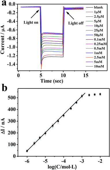 | ||
Fig. 6 (a) Photocurrent responses of the electrode corresponding to different glucose concentrations. (b) A plot of photocurrent decrease (ΔI) of the ITO/PbS/SiO2/AuNPs electrode vs. log![[thin space (1/6-em)]](https://www.rsc.org/images/entities/char_2009.gif) C glucose. C glucose. | ||
| Materials | Detection limit/μM | Linear range/μM | Ref. |
|---|---|---|---|
| PbS/NiO/ITO-GOD | 0.3 | 1.0–1.0 × 10⁴ | 37 |
| PAMAM/poly-HT-GDH | 3.0 | 10.0–1.0 × 10³ | 38 |
| After irradiation | 1.5 | 5.0–1.0 × 10³ | |
| CS/PTh/ITO-GOD | 22.0 | 50.0–2.0 × 10³ | 39 |
| ZnS–CdS/MWCNT/GCE-GOD | 3.0 | 10.0–1.0 × 10³ | 40 |
| PGE-CdS-ZnS-MAA | 50.0 | 2.0 × 10² to 8.0 × 10³ | 41 |
| PbS/SiO2/AuNPs | 0.46 | 1.0–1.0 × 10³ | This work |
Selectivity, reproducibility and stability of the PEC sensor
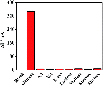
The selectivity of the proposed sensor was then evaluated, as shown in Fig. 7. Common interfering species, such as ascorbic acid (AA), uric acid (UA), cysteine (L-cys), lactose, maltose, and sucrose, were investigated. Although the normal physiological glucose level in human blood is 3–8 mM, nearly 30 times higher than those of many of the interfering species, the interference experiment used glucose at the same concentration as the interfering species (0.1 mM). Clearly, none of these species had any influence except for the glucose, revealing the excellent anti-interference ability against the reductive co-exists in biological samples and hence have great potential in PEC biosensing. The reproducibility of this system was assessed by an inter-assay relative standard deviation (RSD) through testing 1.0 × 10⁻⁴ mM samples with five electrodes, and a RSD of 6.8% was calculated. An intra-assay relative standard deviation (RSD) through testing blank solution six times, and a RSD of 1.2% was calculated. Both of them suggested good reproducibility of the photoelectrode. Fig. S5a† shows the corresponding stability of the photocurrent of the electrode after 60 times of excitation, with no obvious change in cathodic photocurrent response. And the storage stability of the ITO/PbS/SiO2/AuNPs electrode is shown in Fig. S5b.† After four weeks, the current value was 92% of the initial value, exhibiting good stability.Human serum sample measurements
To evaluate the practicability of this glucose sensor, the as-prepared ITO/PbS/SiO2/AuNPs photoelectrode was also employed to determine glucose concentration in human serum samples. These human serum samples were diluted 100 times before detection and standard glucose solutions were added to the samples for recovery test. The results presented in Table S1† showed that the recoveries for the human serum samples were satisfactory. Therefore, it can be stated that the developed glucose sensor is promising for the practical use.Conclusions
In summary, a nanozyme-based PEC glucose sensor using ternary layers of PbS/SiO2/AuNPs was constructed successfully. The TGA-capped PbS quantum dots was PEC active for oxygen. The insert layer of SiO2 nanospheres efficiently reduced base current due to its low electroconductivity. The small AuNPs, a mimic enzyme of GOD, could catalytically oxidize glucose to generate gluconic acid and hydrogen peroxide in the presence of oxygen, which consumed oxygen in situ at electrode surface. This proposed sensor exhibited excellent analytical performance in terms of high sensitivity, good selectivity, and rapid response. In comparison with natural enzyme, nanozymes possess the advantages of high stability, easy preparation, and low cost. It is expected to offer great potential for design and development of nanozyme-based PEC sensors.Conflicts of interest
There are no conflicts to declare.Acknowledgements
This work was financially supported by the National Natural Science Foundation of China (No. 21475092) and the Priority Academic Program Development of Jiangsu Higher Education Institutions.Notes and references
- H. C. Wang and A. R. Lee, J. Food Drug Anal., 2015, 23, 191–200 CrossRef CAS PubMed
.
- A. L. Galant, R. C. Kaufman and J. D. Wilson, Food Chem., 2015, 188, 149–160 CrossRef CAS PubMed
.
- Y. Lin, F. Lu, Y. Tu and Z. Ren, Nano Lett., 2004, 4, 191–195 CrossRef CAS
.
- X. Yunsheng, Y. Jingjing, T. Kanghui, W. Jiajing and Y. Guang, Anal. Chem., 2013, 85, 6241–6247 CrossRef
.
- J. Mu, Y. He and Y. Wang, Talanta, 2016, 148, 22–28 CrossRef CAS PubMed
.
- X. Zhang, X. Bi, W. Di and W. Qin, Sens. Actuators, B, 2016, 231, 714–722 CrossRef CAS
.
- Y. Li, Y. Y. Song, C. Yang and X. H. Xia, Electrochem. Commun., 2007, 9, 981–988 CrossRef CAS
.
- Y. G. Zhou, S. Yang, Q. Y. Qian and X. H. Xia, Electrochem. Commun., 2009, 11, 216–219 CrossRef CAS
.
- X. Zhong, R. Yuan and Y. Q. Chai, Sens. Actuators, B, 2012, 162, 334–340 CrossRef CAS
.
- C. D. A. Marquette and L. J. Blum, Biosens. Bioelectron., 2004, 19, 433–439 CrossRef
.
- S. Aurélie A-M, D. Bastien, L. C. J. Blum, A. P. Girard-Egrot and C. A. Marquette, Anal. Chem., 2010, 82, 2401 CrossRef PubMed
.
- X. Yi, W. Dong, X. Zhang, J. Xie and Y. Huang, Anal. Bioanal. Chem., 2016, 408, 1–8 CrossRef PubMed
.
- C. L. Haynes, C. R. Yonzon, X. Zhang and R. P. V. Duyne, J. Raman Spectrosc., 2005, 36, 471–484 CrossRef CAS
.
- Z. S. Wu, G. Z. Zhou, J. H. Jiang, G. L. Shen and R. Q. Yu, Talanta, 2006, 70, 533–539 CrossRef CAS PubMed
.
- I. Al-Ogaidi, H. Gou, A. K. Al-Kazaz, Z. P. Aguilar, A. K. Melconian, P. Zheng and N. Wu, Anal. Chim. Acta, 2014, 811, 76–80 CrossRef CAS PubMed
.
- J. Lihua, S. Li, G. Shaojun, F. Youxing, W. Dan, W. Li, Y. Jianyuan and D. Shaojun, Biosens. Bioelectron., 2011, 26, 1965–1969 CrossRef PubMed
.
- L. Yu, Z. Na, Q. Fei, T. Wen, F. G. Zhong, N. B. Li and Q. L. Hong, Spectrochim. Acta, Part A, 2014, 118, 315–320 CrossRef PubMed
.
- S. Xiaoyue, C. Lujing, M. Juanjuan, Q. Zhaosheng, C. Jianrong and F. Hui, Analyst, 2014, 139, 2322–2325 RSC
.
- X. Zhang, X. Fang, B. Zhao, J. Xin, Y. Yao, D. Wu, Z. Gao and J. Kai, Electrochim. Acta, 2014, 133, 615–622 CrossRef CAS
.
- M. Zheng, C. Yan, X. Li, S. Liu and Z. Tang, J. Electroanal. Chem., 2011, 656, 167–173 CrossRef CAS
.
- J. Zhang, L. Tu, S. Zhao, G. Liu, Y. Wang, Y. Wang and Z. Yue, Biosens. Bioelectron., 2015, 67, 296–302 CrossRef CAS PubMed
.
- J. Tang, Y. Wang, J. Li, P. Da, J. Geng and G. Zheng, J. Mater. Chem. A, 2014, 2, 6153–6157 RSC
.
- L. Youhui, R. Jinsong and Q. Xiaogang, Acc. Chem. Res., 2014, 47, 1097–1105 CrossRef PubMed
.
- C. L. Clark Jr and C. Lyons, Ann. N. Y. Acad. Sci., 2010, 102, 29–45 CrossRef
.
- Y. Wang, W. Wei, X. Liu and X. Zeng, Mater. Sci. Eng., C, 2009, 29, 50–54 CrossRef CAS
.
- H. Sabahudin, L. Yali, K. B. Male and J. H. T. Luong, Anal. Chem., 2004, 76, 1083–1088 CrossRef PubMed
.
- J. Yun, L. Baoxin and C. Rui, Chem. Commun., 2010, 46, 8017–8019 RSC
.
- M. Comotti, C. D. Pina, R. Matarrese and M. Rossi, Angew. Chem., Int. Ed., 2004, 76, 1083–1088 Search PubMed
.
- P. Beltrame, M. Comotti, C. Della Pina and M. Rossi, Appl. Catal., A, 2006, 297, 1–7 CrossRef CAS
.
- S. S. Marukhyan and V. K. Gasparyan, Spectrochim. Acta, Part A, 2017, 173, 34–38 CrossRef CAS PubMed
.
- Z. Dongdong, L. Weijie, L. Jiang, L. Huajie, M. Hongwei, H. Qing and F. Chunhai, Analyst, 2012, 137, 4435 RSC
.
- Y. Yu, K. Zhang and S. Sun, Appl. Surf. Sci., 2012, 258, 7181–7187 CrossRef CAS
.
- A. Qileng, C. Yue, W. Jie, H. Lei, W. Liu, S. Zhang and Y. Liu, Sens. Actuators, B, 2017, 254, 727–735 CrossRef
.
- T. Cai, G. Yan, J. Yan, W. Ying and J. Di, RSC Adv., 2017, 7, 29122–29128 RSC
.
- T. Kundu and D. Misra, Electrochem. Solid-State Lett., 2005, 8, G35 CrossRef CAS
.
- C. Surbhi, U. Sumant, K. Pushpendra, S. Nirupama, R. S. Vibha, S. Rohit and D. Sahab, Int. J. Hydrogen Energy, 2012, 37, 18713–18730 CrossRef
.
- W. X. Dai, L. Zhang, W. W. Zhao, X. D. Yu, J. J. Xu and H. Y. Chen, Anal. Chem., 2017, 89, 8070–8078 CrossRef CAS
.
- D. G. Dilgin and H. İ. Gökçel, Anal. Methods, 2015, 7, 990–999 RSC
.
- C. Zhao, Z. Zhang, Y. Zhao and J. Yu, Chin. J. Chem., 2012, 30, 1851–1856 CrossRef CAS
.
- Ö. Sağlam and Y. Dilgin, Electroanalysis, 2017, 29, 1368–1376 CrossRef
.
- B. Ertek, C. Akgül and Y. Dilgin, RSC Adv., 2016, 6, 20058–20066 RSC
.
Footnote |
| † Electronic supplementary information (ESI) available. See DOI: 10.1039/c9ra02088h |
| This journal is © The Royal Society of Chemistry 2019 |

