 Open Access Article
Energy-saving electrolytic γ-MnO2 generation: non-noble metal electrocatalyst gas diffusion electrode as cathode in acid solution
Jing Tang *a,
Hui Min Mengb and
Mei Yang Jib
aSchool of Mechanical Engineering, Liaoning Shihua University, Fushun 113001, China. E-mail: fstangcandy@126.com
bCorrosion and Protection Center, Institute for Advance Materials and Technology, University of Science and Technology Beijing, No. 30, Xueyuan Road, Haidian District, Beijing 100083, China. Tel: +86 024 56860273
First published on 9th August 2019
Abstract
γ-MnO2, which is commercially used as an electrode material in batteries, is produced using large amounts of energy and leads to the production of high pollution as a secondary product. Ideally, this material should be fabricated by energy efficient, non-polluting methods at a reasonable cost. This study reports the green fabrication of γ-MnO2 into a gas diffusion electrode with Pt-free catalysts in acid solution. Cobalt oxide nanoparticles were deposited on few-layer graphene sheets produced via a simple sintering and ultrasonic mixing method, leading to the fabrication of cobalt oxide/few-layer graphene. Co3O4 nanoparticles are irregularly shaped and uniformly distributed on the surface of the few-layer graphene sheets. Characterization was conducted by X-ray diffraction, X-ray photoelectron spectroscopy, and field emission scanning electron microscopy. Electrochemical characterization revealed the performance of cobalt oxide/few-layer graphene gas diffusion electrode in an electrolyte of 120 g L−1 manganese sulfate + 30 g L−1 sulfuric acid at 100 A m−2 at 80 °C. The cobalt oxide/few-layer graphene gas diffusion electrode exhibited a lower cell voltage of 0.9 V and higher electric energy savings of approximately 50% compared with traditional cathodes (copper and carbon).
Introduction
Electrolytic manganese dioxide (EMD) may be potentially inexpensive, relatively energy dense, safe, water compatible, and non-toxic when used as an electrode material.1 However, the deposition of EMD, particularly at an industrial scale, not only consumes excessive electric energy but also causes environmental damage because of the acid fog generated by the electrolytic cell.2 Factories have ceased producing EMDs to protect the environment. To overcome this problem, optimization methods have been proposed to reduce the energy required for electrodeposition of manganese dioxide (MnO2). Biswal3 et al. investigated the energy consumption of MnO2 electrodeposition with the introduction of F127 (25F) in the bath and found that energy consumption can be decreased by up to 11%. In our previous work, a platinum (Pt) catalyst gas diffusion electrode (GDE) used as a cathode for electrodeposition of MnO2 is proposed to save energy by approximately 60% and protect the environment.4 In theory, when a Pt catalyst GDE is applied, the oxygen reduction reaction (ORR) replaces the hydrogen evolution reaction (HER). Pt and its alloys are the best-known ORR catalysts5 in acid. However, catalyst-based metal-free materials, such as Pt, are not widely applied6 due to their high cost and low abundance. Although the field of electrode manufacturing has progressed considerably, the development of oxygen electrode catalysts with high activity at low cost in acid remains challenging.7Herein, a metal-free catalyst GDE with cobalt oxide nanoparticles on few-layer graphene (FLG) is proposed as a cathode to save electrical energy (50%) and achieve environment-friendly electrodeposition to meet production requirements. The proposed catalyst and method surprisingly exhibited high performance in acid solution. The manufacturing method of the Co3O4/FLG GDE is simple and inexpensive; it may potentially replace the commercial Pt/C GDE in electrodeposition of MnO2.
Experiment
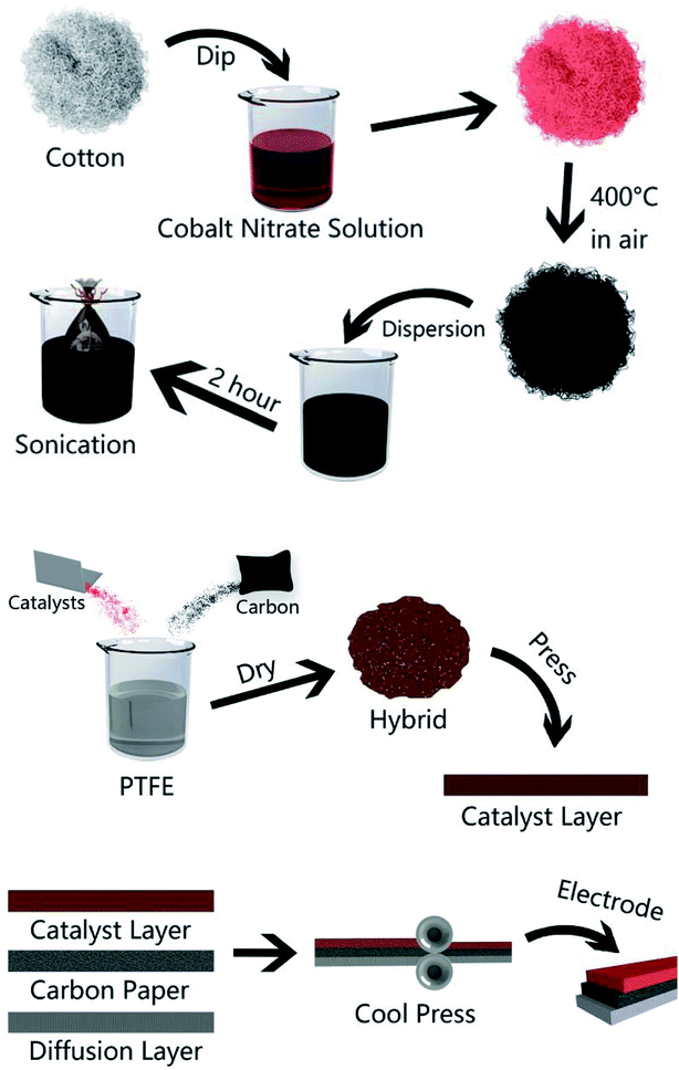
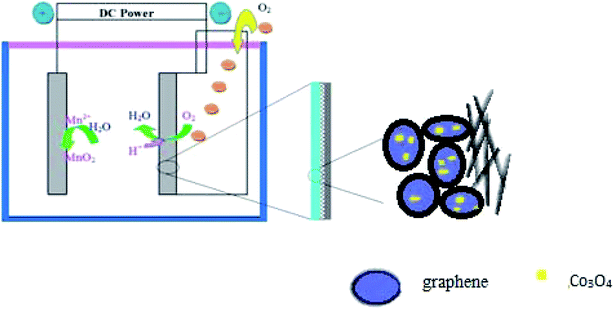
A general two-step method was used to synthesize the Co3O4/FLG catalyst. First, 2.5 g of cotton was sintered with 5 g of cobalt nitrate solution to produce Co3O4 nanoparticles, after which calcination was performed at 400 °C for 2 h8 and then it was milled for 3 h. Then, 0.2 g of Co3O4 nanoparticles was dispersed in 20 mL of ethanol by sonication. Subsequently, few layer graphene wrapped in a microporous membrane (450 μm) was dipped and sonicated in the Co3O4 solution for 8 h and centrifuged to form the Co3O4/FLG hybrid (Fig. 1). The sample was freeze-dried overnight at 60 °C. The GDE is a three-layer structure which consists of diffusive layer, substrate and catalyst layer. Before the experiment began, the 60% PTFE was painted onto carbon paper (Phychemi Company Limited, China), and then it was sintered at 350 °C for 30 min. 0.25 g of acetylene black, 0.3 g of Na2SO4, 0.25 g of activated carbon powder, 0.17 g of 60% PTFE (Hesen, Shanghai, China), and 100 mL of ethanol was mixed and then stirred at 80 °C to wet paste. The wet paste was cool pressed to prepare the diffusion layer (0.4 mm). The catalyst layer was prepared by blending non-noble metal electrocatalysts, carbon black, activated carbon powder, 60% PTFE and 100 mL of ethanol as a dispersant and the rolling process was same as the diffusion layer. Furthermore, the diffusion layer and the catalyst layer was rolled on two sides of the carbon paper to obtain about 0.8 mm flat sheet. The structures and crystal phases of the catalyst were analyzed by X-ray diffraction (XRD Ultima VI) with Cu Kα radiation (λ = 0.15406 nm) operating at 40 kV and 40 mA. The microstructures of the catalyst and GDE were investigated using a transmission electron microscope (TEM, JEOL JEM-2100F). Surface characterization of the samples was conducted by X-ray photoelectron spectroscopy (XPS, AxIS-ULTRA-DLD) with a Mg Kα anode. Binding energies were calibrated based on the C 1s peak (284.8 eV).9 Electrochemical tests were performed using a potentiostat. Here, the working electrodes were GDEs, and a Ti–Mn array was used as the counter electrode at 100 A m−2. The electrolyte was 120 g dm−3 + 30 g dm−3 at 80 °C (Fig. 2).Results and discussion
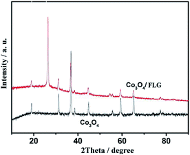
XRD was applied to determine the phase identity and structural information of the samples. Fig. 3 shows the XRD patterns of Co3O4 and Co3O4/FLG. The characteristic peaks of (111), (220), (311), (222), (400), (422), (511), and (440) are in agreement with those of the standard patterns of Co3O4 with a face-centered cubic structure,10 thereby suggesting that Co(NO3)2·6H2O was transformed into Co3O4 at 400 °C. The relatively sharp diffraction peak at 2θ = 24.5°–27.5° in the XRD pattern can be indexed as the graphite layer (200), indicating that the graphene is not single layer. This result is same as the research of Junming Xu.11 The Co3O4 in Co3O4/FLG is relatively weaker than pure Co3O4, possibly resulting in more disordered stacking and less agglomeration on the graphene sheets in the composite.12 Graphene sheets present the advantages of a highly exposed surface area and electrical conductivity, which contribute to the improved electrochemical performance of Co3O4.TEM was performed to confirm the structure of the Co3O4/FLG. The TEM images in Fig. 4 shows several large Co3O4 nanoparticles formed on the graphene sheets, thus suggesting that Co3O4 nanoparticles were doped onto the graphene sheets by the dipping method. Even after considerable sonication during the preparation of the TEM specimen, Co3O4 nanoparticles were still closely distributed on the graphene surface. Co3O4 nanoparticles are irregularly shaped and uniformly distributed on the surface of the graphene sheets. The interplanar distance with a spacing of 0.47 nm is consistent with the (111) facet of Co3O4.13
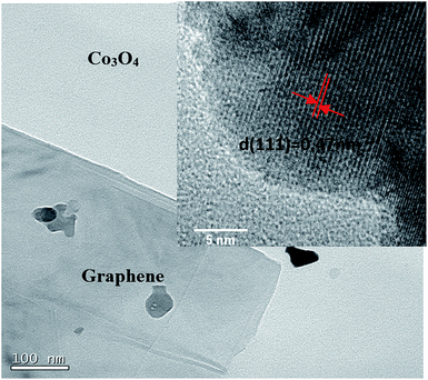 | ||
| Fig. 4 High Resolution Transmission Electron Microscope (HRTEM) images of the Co3O4/FLG and Co3O4 inside. | ||
The XPS spectra reveal the elemental information of the Co3O4/FLG catalyst. From the survey scan of the Co3O4/FLG (Fig. 5a), Co, C, and O are the three elements that make up Co3O4/FLG. This result demonstrates that Co was successfully doped into the graphene sheets via the proposed two-step process. The peak at 284.4 eV (Fig. 5b) is assigned to the characteristic peaks of C 1s.14 Peaks at 284.4, 285.3, and 288.9 eV are attributed to sp2 graphitic carbon (C![[double bond, length as m-dash]](https://www.rsc.org/images/entities/char_e001.gif) C) bonds, carbon bonds with sp3 hybridization, and O–C–O bonds, respectively.15 The peaks located at 780.62 and 795.93 eV (Fig. 5c) are assigned to the binding energies of Co 2p3/2 and Co 2p1/2, respectively, with two prominent shake-up satellite peaks at 786.5 and 804.1 eV, both of which confirm that Co3O4 was obtained.16 The predominant O 1s peak (Fig. 5d) at 530.1 and 532.5 eV corresponds to that of O species in the spinel Co3O4 phase and the hydroxyl groups adsorbed on the surface due to our ex situ experimental conditions, respectively.17 Therefore, Co3O4/FLG is likely composed of Co3O4 on the graphene sheets surface.
C) bonds, carbon bonds with sp3 hybridization, and O–C–O bonds, respectively.15 The peaks located at 780.62 and 795.93 eV (Fig. 5c) are assigned to the binding energies of Co 2p3/2 and Co 2p1/2, respectively, with two prominent shake-up satellite peaks at 786.5 and 804.1 eV, both of which confirm that Co3O4 was obtained.16 The predominant O 1s peak (Fig. 5d) at 530.1 and 532.5 eV corresponds to that of O species in the spinel Co3O4 phase and the hydroxyl groups adsorbed on the surface due to our ex situ experimental conditions, respectively.17 Therefore, Co3O4/FLG is likely composed of Co3O4 on the graphene sheets surface.
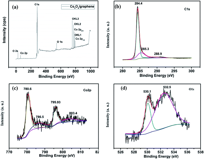 | ||
| Fig. 5 XPS spectra of (a) the Co3O4/FLG, (b) C 1s spectra of the Co3O4/FLG, (c) Co 2p spectra of the Co3O4/FLG and (d) O 1s spectra of the Co3O4/FLG. | ||
Fig. 6 shows the cell voltage of traditional electrode, C GDE and Co3O4/FLG GDE at 100 A m−2 in 30 g dm−3 H2SO4 + 120 g dm−3 MnSO4 at 80 °C. All the average anode potential of the experiments is almost the same which is about 0.62 V vs. Hg2SO4 at 100 A m−2 and the electrodeposition efficiency of γ-MnO2 is not affected. However, the cell voltage of the electrodeposition of MnO2 using Co3O4/FLG GDE as cathode is lower than that of the electrodeposition of MnO2 using traditional electrode. It is because the anode reaction of traditional electrode is the same as that of gas diffusion electrode. The gas diffusion electrode is employed in the electrolytic manganese dioxide cell instead of the traditional electrode, the electrochemical reaction is:
| Anode: Mn2+ + 2H2O → MnO2 + 4H+ + 2e, E0 = 1.23 V vs. SHE | (1) |
| Traditional cathode: 2H+ + 2e → H2, E0 = 0 V vs. SHE | (2) |
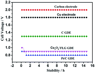 | ||
| Fig. 6 Cell voltage of traditional electrode, carbon electrode, Cu electrode, C GDE, Co3O4/FLG GDE and Pt/C GDE at 100 A m−2 in 30 g dm−3 H2SO4 + 120 g dm−3 MnSO4 at 80 °C. | ||
Gas diffusion electrode as cathode: overall 4 electron reaction forming water
| O2 + 4H+ + 4e → 2H2O, E0 = 1.229 V vs. SHE | (3) |
Or two electron process, forming unwanted H2O2
| O2 + 2H+ + 2e → H2O2, E0 = 0.67 V vs. SHE | (4) |
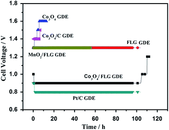
After doping of the Co3O4 nanoparticles into the graphene sheets, the cell voltage of the Co3O4/FLG GDE decreased drastically to 0.9 V, similar to the ORR catalyzed by a high-quality commercial Pt/C GDE (0.8 V). The Pt/C catalyst is acknowledged to be the most effective catalyst for oxygen reduction reaction in acid media. In our previous studies, the ORR, catalysed by the Pt/C catalyst, proceeds via both the two electron transfer and the four-electron transfer, but four-electron transfer is the main process in 30 g dm−3 H2SO4 + 120 g dm−3 MnSO4 at 80 °C.18 However, cell voltage of C GDE in H2SO4 is 0.5 V higher than the Pt/C GDE, as expected, since C GDE features a two electrons transfer to product H2O2 in acid solution which is same as the research of Ichiro Yamanaka.19 The cell voltage of C GDE is 1.3 V which is 0.4 V higher than that of Co3O4/graphene GDE in electrodeposition of γ-MnO2 while it was similar to Pt/C GDE, indicating that ORR of Co3O4/FLG GDE in 30 g dm−3 H2SO4 + 120 g dm−3 MnSO4 at 80 °C is both two electrons transfer (eqn (4)) with the formation of H2O2 and the four-electron transfer (eqn (3)) producing H2O.20
In order to manifest the cause of the high activity of the Co3O4/FLG GDE in the electrodeposition of MnO2, a two-electrode cell assembly was fabricated using the proposed GDE as the cathode, a Ti-based Ti–Mn array as the anode, and 120 g L−1 MnSO4 + 30 g L−1 H2SO4 as the electrolyte. Fig. 7 shows the cell voltage–time curves of Co3O4 GDE, FLG GDE, Co3O4/FLG GDE, Co3O4/C GDE, MnO2/FLG, Pt/C GDE, carbon electrode, and copper electrode at 100 A m−2. Co3O4 exhibited very poor ORR activity with an initial cell voltage of 1.3 V that increased slowly to 1.6 V after 10 h due to its poor conductivity and the small surface area of Co3O4.21 However, The Co3O4/C GDE revealed poor ORR like Co3O4 GDE indicating that C didn't make Co3O4/C GDE work better. The cell voltage of FLG GDE and MnO2/FLG GDE revealed poor ORR activity with a cell voltage of 1.3 V because of low corrosion resistance of the MnO2 and low ORR activity of graphene. However, the Co3O4/FLG nanocatalyst is much more active than either pure Co3O4 or FLG nanocatalysts in the electrodeposition of MnO2. The Co3O4/FLG GDE can save up to ∼50% of the electric energy required by traditional cathodes (Cu and C) in Fig. 6. The increased activity of the proposed GDE may be attributed to synergistic effects between the Co3O4 nanoparticles and FLG22 with the large electrochemically active surface area23 and excellent conductivity,24 which can improve the conductivity and change the charge transfer across the interface. Therefore, Co3O4 doping of FLG plays a key role in improving the electrocatalytic activity of GDEs for green electrodeposition of MnO2 in acid solution.
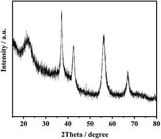
Fig. 8 exhibits XRD patterns of the product of electrolysis. The four sharper peaks appeared at 37.3°, 42.7°, 56.5° and 67.3° which are ascribed to the (021), (121), (221) and (061) planes of γ-MnO2.25,26
Conclusion
In summary, a nanocomposite of Co3O4/FLG was synthesized through a pyrolysis and dipping process. The nanocomposite is simple and easily obtained in the industry. Co3O4/FLG was used as a nanocatalyst to catalyze the ORR in the electrodeposition of MnO2. The proposed Co3O4/FLG nanocomposite GDE exhibited a high activity of 0.9 V at a current density of 100 A m−2, 50% energy savings, and an approximately one fold enhancement compared with those of pure Co3O4 and FLG electrodes, Co3O4/C GDE, and MnO2/FLG GDE. The Co3O4/FLG nanocomposite GDE also displayed better durability in an acid solution (100 h at 100 A m−2 in 120 g L−1 MnSO4 + 30 g L−1 H2SO4) than the Pt-free GDE.Conflicts of interest
There are no conflicts to declare.Acknowledgements
The authors acknowledge the financial support of Scientific Research Project of the Department of Education of Liaoning Province (L2019043) and the Natural Science Foundation of China (51274027).References
- N. D. Ingale, J. W. Gallaway, M. Nyce, A. Couzis and S. Banerjee, J. Power Sources, 2015, 276, 7–18 CrossRef CAS.
- S. R. W. Alwi, Z. A. Manan, J. J. Klemeš and D. Huisingh, J. Cleaner Prod., 2014, 71, 1–10 CrossRef.
- A. Biswal, M. Minakshi and B. C. Tripathy, Dalton Trans., 2016, 45, 5557–5567 RSC.
- J. Tang, H. M. Meng and X. Liang, J. Cleaner Prod., 2016, 137, 903–909 CrossRef CAS.
- I. E. L. Stephens, A. S. Bondarenko, U. Grønbjerg, J. Rossmeisl and I. Chorkendorff, Energy Environ. Sci., 2012, 5, 6744–6762 RSC.
- D. S. Geng, Y. Chen, Y. G. Chen, Y. L. Li, R. Y. Li, X. L. Sun, X. Y. Ye and S. Knights, Energy Environ. Sci., 2011, 4, 760–764 RSC.
- S. Y. Gao, H. Y. Liu and K. Geng, Nano Energy, 2015, 12, 785–793 CrossRef CAS.
- H. Y. Xu, L. B. Gao, Q. Zhang, J. Y. Li, J. T. Diwu, X. J. Chou, J. Tang and C. J. Xue, J. Nanomater., 2014, 2014, 1–9 Search PubMed.
- J. G. Yu, G. P. Dai and B. B. Huang, J. Phys. Chem. C, 2009, 113, 16394–16401 CrossRef CAS.
- K. Wang, R. F. Wang, H. Li, H. Wang, X. F. Mao, V. Linkov and S. Ji, Int. J. Hydrogen Energy, 2015, 40, 3875–3882 CrossRef CAS.
- J. M. Xu, J. S. Wu, L. L. Luo, X. Q. Chen, H. B. Qin, V. Dravid, S. B. Mi and C. L. Jia, J. Power Sources, 2015, 274, 816–822 CrossRef CAS.
- Z. S. Wu, W. C. Ren, L. Wen, L. Gao, J. P. Zhao, Z. P. Chen, G. M. Zhou, F. Li and H. M. Cheng, ACS Nano, 2010, 4, 3187–3194 CrossRef CAS PubMed.
- J. J. Zhang, H. H. Wang, T. J. Zhao, K. X. Zhang, X. Wei, Z. D. Jiang, S. Hirano, X. H. Li and J. S. Chen, ChemSusChem, 2017, 10, 2875–2879 CrossRef CAS PubMed.
- B. J. Li, H. Q. Cao, J. Shao, G. Q. Li, M. Z. Qu and G. Yin, Inorg. Chem., 2011, 50, 1628–1632 CrossRef CAS PubMed.
- A. Siokou, F. Ravani, S. Karakalos, O. Frank, M. Kalbac and C. Galiotis, Appl. Surf. Sci., 2011, 257, 9785–9790 CrossRef CAS.
- H. Xia, D. D. Zhu, Z. T. Luo, Y. Yu, X. Q. Shi, G. L. Yuan and J. P. Xie, Sci. Rep., 2013, 3, 2978 CrossRef PubMed.
- B. B. Varghese, T. C. Hoong, Z. Y. Wu, M. V. Reddy, B. V. Chowdari, A. T. S. Wee, V. B. C. Tan, C. T. Lim and C. H. Sow, Adv. Funct. Mater., 2007, 17, 1932–1939 CrossRef CAS.
- J. Tang, H. M. Meng, S. Li, M. H. Yu, H. Li and J. H. Shi, Electrochim. Acta, 2015, 170, 92–97 CrossRef CAS.
- I. Yamanaka, T. Hashimoto, R. Ichihashi and K. Otsuka, Electrochim. Acta, 2008, 53, 4824–4832 CrossRef CAS.
- K. Wang, R. F. Wang, H. Li, H. Wang, X. F. Mao, V. Linkov and S. Ji, Int. J. Hydrogen Energy, 2015, 40, 3875–3882 CrossRef CAS.
- L. Wang, D. L. Wang, J. S. Zhu and X. Liang, Ionics, 2013, 19, 215–220 CrossRef CAS.
- Y. Y. Liang, Y. G. Li, H. L. Wang, J. G. Zhou, J. Wang, T. Regier and H. J. Dai, Nat. Mater., 2011, 10, 780–786 CrossRef CAS PubMed.
- Q. Liu, J. T. Jin and J. Y. Zhang, ACS Appl. Mater. Interfaces, 2013, 5, 5002–5008 CrossRef CAS PubMed.
- C. X. Wang, P. H. Shi, X. D. Cai, Q. J. Xu, X. J. Zhou, X. L. Zhou, D. Yang, J. C. Fan, Y. L. Min, H. H. Ge and W. F. Yao, J. Phys. Chem. C, 2016, 120, 336–344 CrossRef CAS.
- J. Zhao, Z. Tao, J. Liang and J. Chen, Cryst. Growth Des., 2008, 8, 2799–2805 CrossRef CAS.
- J. Tang, H. M. Meng and L. L. Huang, RSC Adv., 2014, 4, 16512–16516 RSC.
| This journal is © The Royal Society of Chemistry 2019 |

