 Open Access Article
Tremella-like NiO microspheres embedded with fish-scale-like polypyrrole for high-performance asymmetric supercapacitor†
Kehui Hana,
Yan Liuab,
Hui Huanga,
Qinghua Gonga,
Zhiliang Zhanga and
Guowei Zhou *a
*a
aKey Laboratory of Fine Chemicals in Universities of Shandong, School of Chemistry and Pharmaceutical Engineering, Qilu University of Technology (Shandong Academy of Sciences), Jinan 250353, P. R. China. E-mail: gwzhou@qlu.edu.cn; guoweizhou@hotmail.com
bZaozhuang Vocational College of Science & Technology, Tengzhou 277500, P. R. China
First published on 12th July 2019
Abstract
Tremella-like NiO microspheres embedded with fish-scale-like polypyrrole (PPy) were synthesized by polymerizing pyrrole (Py) onto uniform NiO nanosheets. PPy has a fish-scale-like appearance with a thickness of approximately 10 nm, and is connected to the NiO nanosheet surface. NiO/PPy microspheres (diameter of ∼4 μm) were applied as the electrode material in a supercapacitor. The NiO/PPy-6 obtained under a NiO![[thin space (1/6-em)]](https://www.rsc.org/images/entities/char_2009.gif) :
:![[thin space (1/6-em)]](https://www.rsc.org/images/entities/char_2009.gif) Py molar ratio of 6 shows a high specific capacitance of 3648.6 F g−1 at 3 A g−1 and good rate capability (1783 F g−1 at a high current density of 30 A g−1). An asymmetric supercapacitor (ASC) was fabricated using NiO/PPy-6 and activated carbon (AC) as the positive electrode and the negative electrode, respectively. NiO/PPy-6//AC can achieve a high specific capacitance of 937.5 F g−1 at 3 A g−1 and a high energy density of 333.3 W h kg−1 at a power density of 2399.99 W kg−1. The excellent supercapacitor performance is assigned to the combined contribution of both components and the unique heterostructure in NiO/PPy-6.
Py molar ratio of 6 shows a high specific capacitance of 3648.6 F g−1 at 3 A g−1 and good rate capability (1783 F g−1 at a high current density of 30 A g−1). An asymmetric supercapacitor (ASC) was fabricated using NiO/PPy-6 and activated carbon (AC) as the positive electrode and the negative electrode, respectively. NiO/PPy-6//AC can achieve a high specific capacitance of 937.5 F g−1 at 3 A g−1 and a high energy density of 333.3 W h kg−1 at a power density of 2399.99 W kg−1. The excellent supercapacitor performance is assigned to the combined contribution of both components and the unique heterostructure in NiO/PPy-6.
1 Introduction
In modern society, energy conversion and reserves have become important concerns.1,2 The design and fabrication of supercapacitors have recently become hot topics in research owing to the materials' excellent energy density, superior reversibility, and high specific capacitance.3–6 Electrode materials play an important role in the development of supercapacitors;7 in particular, electrode materials used for supercapacitors have three varieties, namely, carbon, polymer, and metal oxides.8 The poor conductivity of carbon materials often limits their applications. Accordingly, as typical electrode materials with Faraday pseudocapacitance, metal oxides and conductive polymers are widely used in the field of supercapacitors.9Metal oxides, as electrode materials for supercapacitors, have received considerable attention owing to their high theoretical energy density, low cost, and low environmental impact. Metal oxides yield specific capacities far below their theoretical values. The rate and cycling performances of metal oxides are also inferior because of poor conductivity and instability during charging/discharging.10,11 Therefore, the preparation of metal oxide composites with excellent properties is needed to improve the performance of metal oxides.12 These composites should exhibit good electrical conductivity and produce new electrochemical properties.13
Polypyrrole (PPy), polyaniline, polyacetylene, polyparaphenylene, and polythiophene are members of a class of organic polymers with high conductivity, and have become hotspots in material science research.14,15 Among these polymers, PPy is a π-bond macromolecular chain structure composed of single and double bonds.16 The conjugated structure enables PPy to have good charge transport capability.17 As a supercapacitor electrode material, PPy can exhibit a capacitance of 200–500 F g−1.18,19 Pure PPy has many advantages, such as large surface area, high capacitance, and chemical stability. However, PPy is rigid and difficult to dissolve in common organic solvents (i.e., ethanol and acetone), has poor mechanical ductility, and is difficult to process into desired products.20
Considering that PPy and metal oxides have their benefits and drawbacks, several composites, such as Co3O4/PPy,21–24 Fe3O4/PPy,25–27 SnO2/PPy,28 NiCo2S4/PPy,15 CoSe2/PPy,29 and VO2/PPy30 were synthesized. However, many factors, including a complex preparation process and high cost, impede the application of these materials.19,20 Owing to the wide range of resources, low cost, and benign environmental impact of NiO, this material has become well known as a supercapacitor material, in which the theoretical capacitance can reach 3230 F g−1 at voltages ranging from 0 V to 0.4 V.1 Several researchers have studied NiO/PPy composites. Fu et al.31 synthesized a flower-like NiO/PPy composite by a two-step process. NiO was prepared by using Ni(OH)2 as the precursor, and then Py was polymerized on its surface. The specific capacitance of the resulting composite was low. However, this value can be increased by regulating the amount of PPy, thereby reaching the maximum capacitance of 595 F g−1. At the interface of the NiO/PPy composite, an internal electric field can be induced, and a synergistic effect can occur between NiO and PPy.31 In particular, the NiO/PPy composite, as a novel electrode material, offers many advantages, such as enlarged contact surface area between the electrode and electrolyte, a short path for ion diffusion, and rich accessible redox reaction sites. Therefore, preparing materials with a stable structure and excellent performance remains a challenge. Our research group prepared tremella-like NiO by using Ni3(NO3)2(OH)4 as a precursor with a capacitance of 3242 F g−1 at 3 A g−1.32 The aim was for the NiO/PPy composite to have the capability to improve supercapacitor performance.
On the basis of the above ideas, we synthesized tremella-like NiO/fish-scale-like PPy by the solvothermal method coupled with in situ polymerization. On the one hand, the tremella-like NiO offers high capacitance. On the other hand, the fish-scale-like PPy not only provides an effective path for electron transport, but also induces additional pseudocapacitance. Owing to the synergistic effect between NiO and PPy, NiO/PPy-6, as the electrode material of the three-electrode system, can achieve a specific capacitance of 3648.6 F g−1 at a current density of 3 A g−1. In addition, an asymmetric supercapacitor (ASC) was prepared using NiO/PPy-6 and activated carbon (AC) as the positive electrode and the negative electrode, respectively. NiO/PPy-6//AC exhibits high specific capacitance and good cycle stability (i.e., the specific capacitance of NiO/PPy-6//AC remains at 88.2% after 10![[thin space (1/6-em)]](https://www.rsc.org/images/entities/char_2009.gif) 000 cycles), and the energy density can reach 333.3 W h kg−1 at a power density of 2399.99 W kg−1. These results signify that NiO/PPy-6 is a competitive electrode in supercapacitor applications.
000 cycles), and the energy density can reach 333.3 W h kg−1 at a power density of 2399.99 W kg−1. These results signify that NiO/PPy-6 is a competitive electrode in supercapacitor applications.
2 Experimental
2.1 Materials
Nickel nitrate hexahydrate (Ni(NO3)2·6H2O) was purchased from Sigma-Aldrich. Carbamide (CO(NH2)2), ammonium persulfate (APS), p-toluenesulfonamide (p-TSA), pyrrole (py), and ethanol are of analytical grade and were purchased from Tianjin Kemiou Chemical Reagent Co. Ltd. (China). AC was bought from Fuzhou Yihuan Carbon Co. Ltd. (China). All chemicals were used without further purification. Ultrapure water (18.2 MΩ cm) was used in all of the experiments.2.2 Preparation of the NiO microspheres
NiO with a tremella-like morphology was synthesized successfully in this study.32 The NiO precursor was synthesized by the solvothermal method. Briefly, 1.70 g of Ni(NO3)2·6H2O and 0.18 g of CO(NH2)2 were dissolved in a mixture of 10 mL ultrapure water and 50 mL ethanol and kept under magnetic stirring to obtain a homogeneous solution. The obtained homogeneous solution was subsequently transferred into an autoclave reactor, which was heated in an oven at 180 °C for 12 h and then cooled naturally to room temperature. The product was washed several times with water and ethanol and then dried at 60 °C. The product was calcined at 350 °C for 2 h to obtain the final product.2.3 Preparation of NiO/PPy
The as-prepared tremella-like NiO was encapsulated by PPy by in situ polymerization in water and alcohol mixture at 0 °C. The obtained tremella-like NiO (0.3 g) was dispersed into an aqueous solution of p-TSA (1.83 g, 60 mL of anhydrous alcohol) and sonicated for 30 min. Subsequently, Py monomer was added to the suspension and then stirred for 1 h. An aqueous solution of APS (40 mL, 1![[thin space (1/6-em)]](https://www.rsc.org/images/entities/char_2009.gif) :
:![[thin space (1/6-em)]](https://www.rsc.org/images/entities/char_2009.gif) 1 molar ratio to Py) was added, and the mixture was shielded from light for 24 h. A series of NiO/PPy samples with different molar ratios of Py and NiO (abbreviated as NiO/PPy-n, where “n” is the molar ratio of NiO to Py, which is 2, 4, 6, 8, and 10 in this study) were synthesized to compare the performances of NiO/PPy samples with different thicknesses. The black samples were washed and dried at 60 °C in air.
1 molar ratio to Py) was added, and the mixture was shielded from light for 24 h. A series of NiO/PPy samples with different molar ratios of Py and NiO (abbreviated as NiO/PPy-n, where “n” is the molar ratio of NiO to Py, which is 2, 4, 6, 8, and 10 in this study) were synthesized to compare the performances of NiO/PPy samples with different thicknesses. The black samples were washed and dried at 60 °C in air.
2.4 Characterization
The external structure of the samples was characterized by field emission scanning electron microscopy (FESEM; Hitachi S-4800) equipped with energy dispersive X-ray spectroscopy (EDS). Transmission electron microscopy (TEM) and high-resolution TEM (HRTEM) measurements were performed using a JEM-2100 electron microscope. The crystal structure of the products was characterized by X-ray diffraction (XRD, Bruker D8 Advance diffractometer) within the 2θ range from 10° to 80°, with Cu Kα radiation at a wavelength of 0.15406 nm. Fourier transform infrared spectroscopy (FT-IR) was collected on a Bruker Tensor 27 spectrometer in the range of 4000–400 cm−1 using KBr pellets. X-ray photoelectron spectroscopy (XPS) measurements were performed using ESCALAB 250 with an Al Kα X-ray source. The specific surface areas and pore size distribution of samples were measured using an N2 adsorption–desorption apparatus (Micromeritics, TriStar 3020). The specific surface areas were calculated by Brunauer–Emmett–Teller (BET) method, and pore diameters were estimated on the basis of the Barrett–Joyner–Halenda (BJH) model.2.5 Electrochemical measurements
The performances of the supercapacitors were tested by three-electrode and two-electrode cells with the PARSTAT 4000 electrochemical workstation. The three-electrode cell used a platinum sheet as the counter electrode, a saturated calomel electrode as the reference electrode, the as-prepared electrode as the working electrode, and 6 mol L−1 of KOH solution as the electrolyte. The two-electrode cell was assembled with the same working electrode material used in the three-electrode cell as the anode and AC as the cathode. The working electrodes were prepared as follows. The synthesized samples, acetylene black, and polyvinylidene fluoride (PVDF) were mixed in a mass ratio of 80![[thin space (1/6-em)]](https://www.rsc.org/images/entities/char_2009.gif) :
:![[thin space (1/6-em)]](https://www.rsc.org/images/entities/char_2009.gif) 10
10![[thin space (1/6-em)]](https://www.rsc.org/images/entities/char_2009.gif) :
:![[thin space (1/6-em)]](https://www.rsc.org/images/entities/char_2009.gif) 10 in N-methyl-2-pyrrolidinone to form a homogeneous slurry. The slurry was coated with nickel foam as the current collector, and the electrode area was 1 cm2. The electrode was dried at 80 °C under vacuum for 12 h. The electrochemical performances were analyzed by cyclic voltammetry (CV), galvanostatic charge–discharge (GCD), and electrochemical impedance spectroscopy (EIS). For the three-electrode cell, CV curves were measured at potentials of 0–0.4 V, and GCD tests were conducted at potentials of 0–0.37 V. For the two-electrode cell, CV curves were measured at potentials of 0–1.6 V, and GCD tests were conducted at potentials of 0–1.6 V.
10 in N-methyl-2-pyrrolidinone to form a homogeneous slurry. The slurry was coated with nickel foam as the current collector, and the electrode area was 1 cm2. The electrode was dried at 80 °C under vacuum for 12 h. The electrochemical performances were analyzed by cyclic voltammetry (CV), galvanostatic charge–discharge (GCD), and electrochemical impedance spectroscopy (EIS). For the three-electrode cell, CV curves were measured at potentials of 0–0.4 V, and GCD tests were conducted at potentials of 0–0.37 V. For the two-electrode cell, CV curves were measured at potentials of 0–1.6 V, and GCD tests were conducted at potentials of 0–1.6 V.
Specific capacitance, which was determined from the charge–discharge curve, was calculated as follows [eqn (1)]:
 | (1) |
The energy density (E) and the power density (P) of the assembled supercapacitor were calculated on the basis of the charge–discharge curves as follows [eqn (2) and (3)]:
 | (2) |
 | (3) |
3 Results and discussion
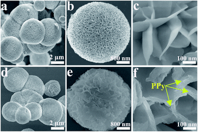
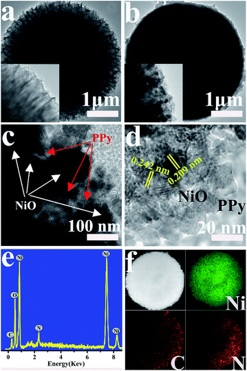
Fig. S1† shows the FESEM images of the prepared Ni3(NO3)2(OH)4 precursors. The precursor is completely orbicular with a diameter of ∼4 μm, and the nanosheets are tightly packed with a thickness of ∼10 nm. The morphologies of NiO and NiO/PPy are characterized by FESEM, as shown in Fig. 1. As shown in Fig. 1a and d, the low-magnification findings are uniform for the NiO and NiO/PPy-6 microspheres. The diameter (∼4 μm) of the tremella-like NiO microsphere is composed of nanosheets with a thickness of ∼10 nm (Fig. 1a and b). The nanosheets can provide additional space for Py polymerization and shorten the length of ion diffusion in the electrolyte. Fig. 1c and d show the NiO/PPy microsphere with a compact structure, and the nanosheets are thick at ∼30 nm.The microstructures of NiO and NiO/PPy are further analyzed by TEM and HRTEM (Fig. 2). The TEM images of the NiO and NiO/PPy microspheres are shown in Fig. 2a and b. The NiO microsphere is uniformly embedded with PPy in the NiO gaps (Fig. 2c). Fig. 2d shows that the PPy is fish-scale-like, with a thickness of ∼10 nm and connected to the surface of an NiO nanosheet. The morphology and size of the NiO and NiO/PPy microspheres conform with the FESEM results. In addition, PPy has a fish-scale-like morphology, which can provide additional active sites for OH− insertion.33–35 Energy-dispersive X-ray (EDX) spectroscopy (Fig. 2e) reveals that Ni, O, C, and N elements exist in the NiO/PPy microspheres. The mapping images (Fig. 2f) confirm the distribution of the constituents of NiO/PPy with Ni, N, and C elements.
The synthesis mechanism of the NiO/PPy microspheres is depicted in Scheme 1. First, Ni(NO3)2·6H2O slowly undergoes alcoholysis in ethanol and CO(NH2)2 to form tremella-like Ni3(NO3)2(OH)4 microspheres.32 Tremella-like NiO microspheres can be obtained after calcination. Then, the PPy layers are grown on the surfaces of the NiO nanosheets by the chemical oxidation polymerization of Py.36,37 Wrinkly PPy films with fish-scale-like morphologies on the surfaces of the NiO nanosheets are fabricated.
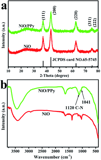
Compared with the XRD spectrum of pure NiO, the XRD spectrum of NiO/PPy is not affected during Py polymerization (Fig. 3a). All diffraction peaks of NiO/PPy are the same as those of NiO (JCPDS: 65-5745). This finding suggests the lack of influence on the crystal structure of NiO after Py polymerization, and the fish-scale-like PPy is an amorphous structure. The XRD patterns of the pristine precursors were subsequently compared, as shown in Fig. S2.† All diffraction peaks located at 13.1°, 26.0°, 34.2°, 35.9°, 43.8°, 53.9°, 59.8°, and 61.0° can be indexed to the (001), (002), (100), (101), (102), (103), (110), and (111) hexagonal structures of Ni3(NO3)2(OH)4 (JCPDS card no. 22-0752). The FT-IR spectra of the NiO and NiO/PPy microspheres are also obtained to further investigate the NiO/PPy, as shown in Fig. 3b. In the FT-IR spectrum of NiO/PPy, two new peaks located at 1120 cm−1 (associated with the C–N bond) and 1041 cm−1 (associated with the Py ring), which are characteristic absorption peaks, are observed after in situ polymerization.
Fig. S3† shows that all samples exhibit typical type-IV isotherms with clear hysteresis loops of H3 type, which indicate typical mesoporous structures. As shown in Fig. S3b,† the pore sizes of NiO and NiO/PPy are mainly in the mesoporous range (∼5 nm). The specific surface areas of NiO and NiO/PPy are 150 and 248 m2 g−1, and the pore volumes of NiO and NiO/PPy are 3.906 and 6.209 m3 g−1, respectively. That is, NiO/PPy possesses a larger surface area and pore volume than NiO.
The XPS spectrum of NiO/PPy shows that Ni, O, C, and N coexist in the composite (Fig. 4a). Fig. 4b shows that the two peaks detected at 854.0 and 872.6 eV for the Ni 2p spectra of NiO/PPy, are assigned to Ni 2p3/2 and Ni 2p1/2, can be ascribed to Ni2+.38 The C 1s spectrum of XPS is fitted into three components (Fig. 4c). The peaks at 284.1, 286.0, and 287.5 eV correspond to Cβ and Cα PPy (C–C), C–OH or C![[double bond, length as m-dash]](https://www.rsc.org/images/entities/char_e001.gif) N, and C
N, and C![[double bond, length as m-dash]](https://www.rsc.org/images/entities/char_e001.gif) O, respectively.39 In the N 1s XPS spectra (Fig. 4d), the peak at 397.8 eV can be attributed to the imine-like (
O, respectively.39 In the N 1s XPS spectra (Fig. 4d), the peak at 397.8 eV can be attributed to the imine-like (![[double bond, length as m-dash]](https://www.rsc.org/images/entities/char_e001.gif) N–) morphology, the peak at 399.2 eV corresponds to Py nitrogen (–NH–), and the peak at 401.1 eV can be assigned to positively charged nitrogen (–NH+–).15
N–) morphology, the peak at 399.2 eV corresponds to Py nitrogen (–NH–), and the peak at 401.1 eV can be assigned to positively charged nitrogen (–NH+–).15
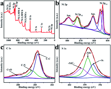 | ||
| Fig. 4 XPS survey spectrum for NiO/PPy (a). High-resolution XPS spectra (b) Ni 2p, (c) C 1s, and (d) N 1s. | ||
Fig. 5a shows the CV curves of NiO and NiO/PPy-n tested at a scan rate of 10 mV s−1 in the three-electrode system. The CV curves of NiO and NiO/PPy-n present two pairs of redox peaks. With the increase in molar ratio of NiO to Py, the area of the CV curve is increased until the molar ratio of NiO to Py is 6. At the same scan rate, NiO/PPy-6 has the highest specific capacitance. When the amount of PPy increases, the excess in PPy hinders the OH− ion from entering the NiO.15,29,40 The mechanism is attributed to the reversible faradaic redox of Ni2+/Ni3+, according to the following equation:32,41
| NiO + OH− ↔ NiOOH + e− |
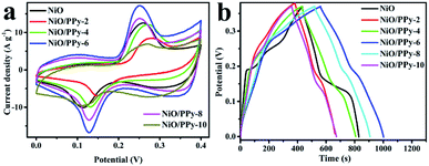 | ||
| Fig. 5 Comparison of CV curves of NiO and NiO/PPy at a scan rate of 10 mV s−1 (a). Comparison of GCD curves of NiO and NiO/PPy at a current density of 3 A g−1 (b). | ||
Fig. 5b shows the GCD curves of NiO and NiO/PPy-n tested at a current density of 3 A g−1. The NiO/PPy-6 electrode has the longest discharge time among all samples. The results indicate that NiO/PPy-6 is the optimal electrode in the supercapacitors.
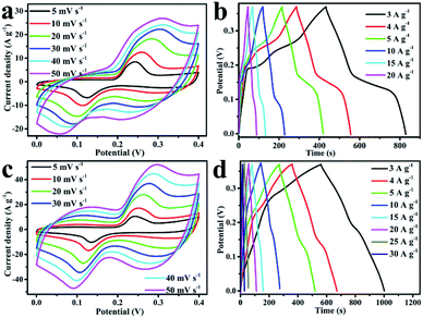
The CV curves of NiO and NiO/PPy-6 at different scan rates are shown in Fig. 6a and c. When the scan rate increases, the polarization effect of the electrode is enhanced, and oxidation peaks and reduction peaks move to a high potential and a low potential, respectively.1 The CV curves of NiO/PPy-6 appear with a symmetrical shape (Fig. 6c), suggesting an increase in coulombic efficiency and a decrease in polarization loss.1,42 The GCD curves of NiO and NiO/PPy-6 have good symmetry (Fig. 6b and d), indicating superior reversible redox capabilities. Fig. S4a† shows the specific capacitance of NiO and NiO/PPy-6 at various current densities. When the current density increases from 3 A g−1 to 30 A g−1, the capacitance of the NiO/PPy-6 electrode decreases from 3648.6 F g−1 to 1783 F g−1. The capacitance of the NiO electrode decreases from 3242 F g−1 to 81 F g−1 when the current density increases from 3 A g−1 to 20 A g−1. Nevertheless, at each current density, the specific capacitance of NiO/PPy is larger than that of NiO. A comparison of NiO/PPy-6 and NiO composite electrodes is provided in Table S1.†
EIS measurement was carried out in the frequency range from 100 kHz to 0.01 Hz. Fig. S4b† shows the Nyquist plots of NiO and NiO/PPy-6. In the high-frequency region, the semicircular diameter of NiO/PPy-6 is smaller than that of NiO, which indicates that the introduction of PPy can increase OH− ion transport.43,44 In the low-frequency region, the line slope of NiO/PPy-6 is larger than that of NiO, which demonstrates that the diffusion resistance of NiO/PPy-6 is lower than that of NiO.45,46 Therefore, NiO/PPy-6 has superior capacitance properties.
In further evaluating the advantages of NiO/PPy-6 composites in practical applications, NiO/PPy-6//AC ASC is fabricated using NiO/PPy-6 and AC as the positive electrode and negative electrode, respectively. The negative electrode is prepared by the traditional slurry coating method. AC, acetylene black, and PVDF are mixed in a mass ratio of 80![[thin space (1/6-em)]](https://www.rsc.org/images/entities/char_2009.gif) :
:![[thin space (1/6-em)]](https://www.rsc.org/images/entities/char_2009.gif) 10
10![[thin space (1/6-em)]](https://www.rsc.org/images/entities/char_2009.gif) :
:![[thin space (1/6-em)]](https://www.rsc.org/images/entities/char_2009.gif) 10. PVDF is dissolved in N-methylpyrrolidone, then the sample and acetylene black are dispersed in the above solution. The mixtures are ground adequately to form a slurry. Subsequently, the slurry is pasted onto the treated Ni foam and dried at 85 °C for 24 h. Fig. 7a presents a schematic illustration of ASC, while Fig. S5† shows the CV and GCD curves of AC. The capacitance of NiO, NiO/PPy-6, and AC at 3 A g−1 are 656.2 F g−1, 937.5 F g−1, and 480 F g−1, respectively.
10. PVDF is dissolved in N-methylpyrrolidone, then the sample and acetylene black are dispersed in the above solution. The mixtures are ground adequately to form a slurry. Subsequently, the slurry is pasted onto the treated Ni foam and dried at 85 °C for 24 h. Fig. 7a presents a schematic illustration of ASC, while Fig. S5† shows the CV and GCD curves of AC. The capacitance of NiO, NiO/PPy-6, and AC at 3 A g−1 are 656.2 F g−1, 937.5 F g−1, and 480 F g−1, respectively.
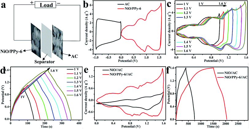
CV curves of NiO/PPy-6 and AC are measured at 30 mV s−1 in a three-electrode system to determine the total voltage, as shown in Fig. 7b. The voltage window of the ASC device is predicted to reach 1.6 V. Fig. 7c and d show the CV and GCD curves of ASC. The results also show that the voltage of ASC can reach 1.6 V. NiO/PPy-6//AC has a large CV area and high capacitance compared with NiO//AC (Fig. 7e). Fig. 7f presents the discharge time of NiO/PPy-6//AC (500 s), which is longer than that of NiO//AC (349.9 s) at 3 A g−1.
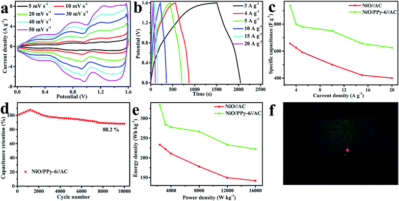
CV curves of NiO/PPy-6//AC and NiO//AC in the voltage window of 0–1.6 V at different scan rates are shown in Fig. 8a and S6a.† When the scan rate increases, the CV curve is maintained, suggesting a satisfactory rate and good cycling performance of ASC.47,48 The GCD curves of NiO/PPy-6//AC and NiO//AC at the different current densities of 3–20 A g−1 in the voltage window of 0–1.6 V are shown in Fig. 8b and S6b.† As shown in Fig. 8c, at the current densities of 3 A g−1 and 20 A g−1, the NiO/PPy-6//AC has a high specific capacitance of 937.5 F g−1 and 625 F g−1, which are higher than those of the NiO//AC (656.2 F g−1 and 400 F g−1). The cycle stability, an important parameter for supercapacitors, of NiO/PPy-6//AC can be valued by its consecutive GCD at 10 A g−1 for 10![[thin space (1/6-em)]](https://www.rsc.org/images/entities/char_2009.gif) 000 cycles. As shown in Fig. 8d, the capacitance retention is over 100% for 1200 cycles and then gradually decreases.20,49 After 10
000 cycles. As shown in Fig. 8d, the capacitance retention is over 100% for 1200 cycles and then gradually decreases.20,49 After 10![[thin space (1/6-em)]](https://www.rsc.org/images/entities/char_2009.gif) 000 cycles, the specific capacitance of NiO/PPy-6//AC remains at 88.2% of the initial value, indicating excellent long-term cycling stability. Power and energy densities, as the two significant parameters of supercapacitors, are obtained based on ASC to identify the applicability of the special materials. Fig. 8e shows a comparison of the Ragone plots of NiO//AC and NiO/PPy-6//AC. At the current densities of 3 A g−1 and 20 A g−1, NiO/PPy-6//AC has energy densities of 333.3 W h kg−1 and 222.22 W h kg−1 at power densities of 2399.8 W kg−1 and 15
000 cycles, the specific capacitance of NiO/PPy-6//AC remains at 88.2% of the initial value, indicating excellent long-term cycling stability. Power and energy densities, as the two significant parameters of supercapacitors, are obtained based on ASC to identify the applicability of the special materials. Fig. 8e shows a comparison of the Ragone plots of NiO//AC and NiO/PPy-6//AC. At the current densities of 3 A g−1 and 20 A g−1, NiO/PPy-6//AC has energy densities of 333.3 W h kg−1 and 222.22 W h kg−1 at power densities of 2399.8 W kg−1 and 15![[thin space (1/6-em)]](https://www.rsc.org/images/entities/char_2009.gif) 999 W kg−1, respectively. These values are higher than those of NiO//AC. For further application of ASC in actual life, the above configuration can easily light LED indicators (Fig. 8f).
999 W kg−1, respectively. These values are higher than those of NiO//AC. For further application of ASC in actual life, the above configuration can easily light LED indicators (Fig. 8f).
4 Conclusions
Tremella-like NiO/fish-scale-like PPy microspheres were fabricated by solvothermal and in situ polymerization methods. The nanosheets of tremella-like NiO limit the Py chemical oxidation polymerization, which can subsequently shorten the distance of OH− ion diffusion. The fish-scale-like PPy can provide many active sites. As an electrode material in supercapacitors, the combination of NiO/PPy produces an advantageous synergistic effect. The optimized NiO/PPy-6 achieved a high specific capacitance of 3648.6 F g−1 at 3 A g−1. NiO/PPy-6//AC ASC was assembled using NiO/PPy-6 and AC as the positive electrode and the negative electrode, respectively. The ASC device can achieve high specific capacitance of 937.5 F g−1 at 3 A g−1 and an energy density of 333.3 W h kg−1 at a power density of 2399.99 W kg−1. The specific capacitance of NiO/PPy-6//AC remains at 88.2% after 10![[thin space (1/6-em)]](https://www.rsc.org/images/entities/char_2009.gif) 000 cycles, indicating excellent long-term cycling stability. Consequently, NiO/PPy-6//AC is a competitive candidate for energy conversion and reserve devices.
000 cycles, indicating excellent long-term cycling stability. Consequently, NiO/PPy-6//AC is a competitive candidate for energy conversion and reserve devices.
Conflicts of interest
There are no conflicts to declare.Acknowledgements
This work was supported by the National Natural Science Foundation of China (Grant No. 51572134, 51372124) and the Program for Scientific Research Innovation Team in Colleges and Universities of Jinan (Grant No. 2018GXRC006).Notes and references
- H. W. Lai, Q. Wu, J. Zhao, L. M. Shang, H. Li, R. C. Che, Z. Y. Lyu, J. F. Xiong, L. J. Yang, X. Z. Wang and Z. Hu, Energy Environ. Sci., 2016, 9, 2053–2060 RSC.
- B. Dunn, H. Kamath and J. M. Tarascon, Science, 2011, 334, 928–935 CrossRef CAS PubMed.
- Y. Shi, J. Zhang, A. M. Bruck, Y. M. Zhang, J. Li, E. A. Stach, K. J. Takeuchi, A. C. Marschilok, E. S. Takeuchi and G. H. Yu, Adv. Mater., 2017, 29, 1603922–1603929 CrossRef PubMed.
- A. Gupta, P. Singh, C. Mullins, M. Buddie and J. B. Goodenough, Chem. Mater., 2016, 28, 4641–4645 CrossRef CAS.
- K. Naoi, W. Naoi, S. Aoyagi, J. I. Miyamoto and T. Kamino, Acc. Chem. Res., 2012, 46, 1075–1083 CrossRef PubMed.
- R. R. Salunkhe, C. Young, J. Tang, T. Takei, Y. Ide, N. Kobayashi and Y. Yamauchi, Chem. Commun., 2016, 52, 4764–4767 RSC.
- R. R. Salunkhe, Y. V. Kaneti, J. Kim, J. H. Kim and Y. Yamauchi, Acc. Chem. Res., 2016, 49, 2796–2806 CrossRef CAS.
- S. G. Chen, Z. D. Wei, X. Q. Qi, L. C. Dong, Y. G. Guo, L. J. Wan, Z. G. Shao and L. Li, J. Am. Chem. Soc., 2012, 134, 13252–13255 CrossRef CAS.
- Q. X. Xia, J. Fu, J. M. Yun, R. S. Maneb and K. H. Kim, RSC Adv., 2017, 7, 11000–11011 RSC.
- S. R. Ede, S. Anantharaj, K. T. Kumaran, S. Mishrab and S. Kundu, RSC Adv., 2017, 7, 5898–5911 RSC.
- Q. H. Gong, Y. J. Li, H. Huang, J. Zhang, T. T. Gao and G. W. Zhou, Chem. Eng. J., 2018, 344, 290–298 CrossRef CAS.
- X. Wang, T. M. Wang, D. Liu, J. S. Guo and P. Liu, Ind. Eng. Chem. Res., 2016, 55, 866–874 CrossRef CAS.
- J. H. Yang, X. Xie, Z. Z. He, Y. Lu, X. D. Qi and Y. Wang, Chem. Eng. J., 2019, 355, 137–149 CrossRef CAS.
- S. Saha, M. Jana, P. Khanra, P. Samanta, H. Koo, N. C. Murmub and T. Kuila, RSC Adv., 2016, 6, 1380–1387 RSC.
- J. F. Sun, Y. Huang, C. X. Fu, Z. Y. Wang, Y. Huang, M. S. Zhu, C. Y. Zhi and H. Hu, Nano Energy, 2016, 27, 230–237 CrossRef CAS.
- T. Y. Tao, J. F. Ruan, W. M. Zhang, Z. P. Tan, J. H. Yang, Z. F. Ma and S. Y. Zheng, ACS Appl. Mater. Interfaces, 2016, 8, 35114–35122 CrossRef.
- J. Xu, A. Palumbo, W. Xu and E. H. Yang, J. Phys. Chem. B, 2016, 120, 10381–10386 CrossRef CAS.
- B. B. Yue, C. Y. Wang, W. Pawel, Y. Yang, X. Ding, D. L. Officer and G. G. Wallace, Synth. Met., 2012, 162, 2216–2221 CrossRef CAS.
- M. L. Yan, Y. D. Yao, J. Q. Wen, L. Long, M. L. Kong, G. G. Zhang, X. M. Liao, G. F. Yin and Z. B. Huang, ACS Appl. Mater. Interfaces, 2016, 8, 24525–24535 CrossRef CAS.
- X. R. Sun, H. W. Zhang, L. Zhou, X. D. Huang and C. Z. Yu, Small, 2016, 12, 3732–3737 CrossRef CAS.
- X. M. Wu, L. Meng, Q. G. Wang, W. Z. Zhang and Y. Wang, Chem. Eng. J., 2017, 327, 193–201 CrossRef CAS.
- W. Hong, J. Q. Wang, Z. P. Li and S. G. Yang, J. Mater. Chem. A, 2015, 3, 2535–2540 RSC.
- L. J. Han, P. Y. Tang and L. Zhang, Nano Energy, 2014, 7, 42–51 CrossRef CAS.
- P. B. Liu, Y. Huang, L. Wang and W. Zhang, J. Alloys Compd., 2013, 573, 151–156 CrossRef CAS.
- L. Z. Bai, Z. P. Li, Y. Zhang, T. Wang, R. H. Lu, W. F. Zhou, H. X. Gao and S. B. Zhang, Chem. Eng. J., 2015, 279, 757–766 CrossRef CAS.
- J. Liu, X. J. Xu, R. Z. Hu, L. C. Yang and M. Zhu, Adv. Energy Mater., 2016, 6, 1600256–1600262 CrossRef.
- Y. Wang, Y. Zhang, C. Hou and M. Z. Liu, Microchim. Acta, 2016, 183, 1145–1152 CrossRef CAS.
- J. J. Yuan, C. H. Chen, Y. Hao, X. K. Zhang, B. Zou, R. Agrawal, C. L. Wang, H. J. Yu, X. R. Zhu, Y. Yu, Z. Z. Xiong, Y. Luo, H. X. Li and Y. M. Xie, J. Alloys Compd., 2017, 691, 34–39 CrossRef CAS.
- Q. F. Wang, Y. Ma, X. Liang, D. H. Zhang and M. G. Miao, J. Mater. Chem. A, 2018, 6, 10361–10369 RSC.
- P. Man, Q. C. Zhang, J. Sun, J. B. Guo, X. N. Wang, Z. Y. Zhou, B. He, Q. L. Li, L. Y. Xie, J. X. Zhao, C. W. Li, Q. G. Li and Y. G. Yao, Carbon, 2018, 139, 21–28 CrossRef CAS.
- W. J. Ji, J. Y. Ji, X. H. Cui, J. J. Chen, D. J. Liu, H. Deng and Q. Fu, Chem. Commun., 2015, 51, 7669–7672 RSC.
- K. H. Han, H. Huang, Q. H. Gong, T. T. Si, Z. L. Zhang and G. W. Zhou, J. Mater. Sci., 2018, 53, 12477–12491 CrossRef CAS.
- S. M. Wang, T. T. Gao, Y. Li, S. C. Li and G. W. Zhou, J. Solid State Electrochem., 2016, 21, 705–714 CrossRef.
- J. Zhang, Y. J. Li, T. T. Gao, X. F. Sun, P. Cao and G. W. Zhou, Ceram. Int., 2018, 44, 8550–8555 CrossRef CAS.
- X. Zhang, R. F. Zhao, Q. H. Wu, W. L. Li, C. Shen, L. B. Ni, H. Yan, G. W. Diao and M. Chen, ACS Nano, 2017, 11, 8429–8436 CrossRef CAS.
- C. F. Yang, L. L Li, J. X. Zhao, J. J. Wang, J. X. Xie, Y. P. Cao, M. Q. Xue and C. H. Lu, ACS Appl. Mater. Interfaces, 2018, 10, 25811–25818 CrossRef CAS.
- X. Yang, Y. Zhao, J. X. Xie, H. Xue, J. J. Wang, C. Y. Zong, H. P. Ji, J. X. Zhao, S. C. Jiang, Y. P. Cao and C. H. Lu, ACS Nano, 2016, 10, 3801–3808 CrossRef CAS.
- L. F. Shen, J. Wang, G. Y. Xu, H. S. Li, H. Dou and X. G. Zhang, Adv. Energy Mater., 2015, 5, 1400977–1400983 CrossRef.
- V. A. Zinovyeva, M. A. Vorotyntsev, I. Bezverkhyy, D. Chaumont and J. C. Hierso, Adv. Funct. Mater., 2011, 21, 1064–1075 CrossRef CAS.
- C. Zhou, Y. W. Zhang, Y. Y. Li and J. P. Liu, Nano Lett., 2013, 13, 2078–2085 CrossRef CAS.
- J. Yang, M. G. Ma, C. C. Sun, Y. F. Zhang, W. Huang and X. C. Dong, J. Mater. Chem. A, 2014, 3, 1258–1264 RSC.
- F. Zhang, Y. Y. Bao, S. S. Ma, L. Liu and X. Shi, J. Mater. Chem. A, 2017, 5, 7474–7481 RSC.
- X. Li, J. P. Rong and B. Q. Wei, ACS Nano, 2010, 4, 6039–6049 CrossRef CAS.
- Z. K. Li, Y. Yao, Y. J. Zheng, T. T. Gao, Z. H. Liu and G. W. Zhou, J. Electrochem. Soc., 2018, 165, E58–E63 CrossRef CAS.
- L. Wei, M. Sevilla, A. B. Fuertes, R. Mokaya and G. Yushin, Adv. Energy Mater., 2010, 1, 356–361 CrossRef.
- K. P. Wang and H. S. Teng, J. Electrochem. Soc., 2007, 154, A993–A998 CrossRef CAS.
- Y. Qian, R. Liu, Q. F. Wang, J. Xu, D. Chen and G. Z. Shen, J. Mater. Chem. A, 2014, 2, 10917–10922 RSC.
- L. Li, Y. Q. Zhang, F. Shi, Y. J. Zhang, J. H. Zhang, C. D. Gu, X. L. Wang and J. P. Tu, ACS Appl. Mater. Interfaces, 2014, 6, 18040–18047 CrossRef CAS.
- M. C. Liu, J. J. Li, W. Han and L. Kang, J. Energy Chem., 2016, 25, 601–608 CrossRef.
Footnote |
| † Electronic supplementary information (ESI) available: Fig. S1 FESEM images of Ni3(NO3)2(OH)4 precursors; Fig. S2 XRD images of Ni3(NO3)2(OH)4 precursors; Fig. S3 (a) N2 adsorption–desorption isotherms of NiO and NiO/PPy (b) the pore size distribution of NiO and NiO/PPy; Fig. S4 (a) specific capacitance of NiO and NiO/PPy; (b) Nyquist plots of NiO and NiO/PPy; Fig. S5 (a) CV curves of the AC at different scan rates; (b) GCD curves of the AC at different current densities; Fig. S6 (a) CV curves of NiO//AC at different scan rates; (b) GCD curves of NiO//AC at different current densities; Table S1 comparison of synthesis methods, morphology, and electrochemical performances of different NiO composite electrodes. See DOI: 10.1039/c9ra03046h |
| This journal is © The Royal Society of Chemistry 2019 |

