 Open Access Article
Inverted vortex fluidic exfoliation and scrolling of hexagonal-boron nitride†
Ahmed Hussein Mohammed Al-Antaki ab,
Xuan Luoa,
Thaar M. D. Alharbia,
David P. Harveya,
Scott Pye
 a,
Jin Zou
 c,
Warren Lawranced and
Colin L. Raston
 *a
*a
aFlinders Institute for Nanoscale Science and Technology, College of Science and Engineering, Flinders University, Adelaide, SA 5042, Australia. E-mail: colin.raston@flinders.edu.au
bDepartment of Chemistry, Faculty of Sciences, Kufa University, Kufa, Najaf, Iraq
cMaterials Engineering, Centre for Microscopy and Microanalysis, The University of Queensland, Brisbane, QLD 4072, Australia
dCollege of Science and Engineering, Flinders University, Adelaide, SA 5042, Australia
First published on 16th July 2019
Abstract
Exfoliation or scrolling of hexagonal boron nitride (h-BN) occurs in a vortex fluidic device (VFD) operating under continuous flow, with a tilt angle of −45° relative to the horizontal position. This new VFD processing strategy is effective in avoiding the build-up of material that occurs when the device is operated using the conventional tilt angle of +45°, where the h-BN precursor and scrolls are centrifugally held against the wall of the tube. At a tilt angle of −45° the downward flow aided by gravity facilitates material exiting the tube with the exfoliation of h-BN and formation of h-BN scrolls then optimized by systematically varying the other VFD operating parameters, including flow rate and rotational speed, along with concentration of h-BN and the choice of solvent. Water was the most effective solvent, which enhances the green chemistry metrics of the processing.
Introduction
Polymorphs of boron nitride include the hexagonal arrangement of alternating boron and nitrogen atoms in 2D sheets, with the atoms sp2 hybridized, comparable to that of graphite. However, in contrast to graphite, layered hexagonal boron nitride (h-BN) is transparent and it is an insulator,1 but nevertheless it has attracted considerable attention. Other polymorphs of h-BN do not strictly match polymorphs of carbon, for example, as in the boron nitride analogues of fullerenes, known as fulborenites.2,3 The main polymorphs of boron nitride are rhombohedral BN (r-BN), cubic BN (c-BN), wurtzite BN (w-BN) and hexagonal BN (h-BN), with the latter 2D material featuring in the present study. None of the polymorphs of BN have been found in nature.4In general, hexagonal carbon (h-C), possessing hexagonal six membered rings, as in graphite, graphene or carbon nanotubes, can be metallic or semiconducting depending on the dimensions and overall structure. However, h-BN is an insulator or indirect semiconductor, having a large band gap around 5.9 eV.5 Defects in h-BN can perturb the band gap5 with single crystals of h-BN flakes used to study band gap properties.5,6 The availability of high-quality h-BN flakes is important for developing applications in far-ultraviolet (FUV) light-emitting diodes (LEDs).7 In addition, h-BN has potential in optoelectronic applications, for use in high-performance electronic devices. Electron energy loss spectroscopy (EELS) on the ionization edge between two-layers of BN is effective in determining the number of layers of one atom thick h-BN.8 h-BN can also be coerced into forming scrolls which are essentially individual sheets of h-BN rolled up at the van der Waals limit.9–11 Contemporary studies have established the ability to make the analogous graphene and graphene oxide scrolls.11–16 h-BN scrolls have a number of potential applications, as platforms for the delivery of composites and nucleobases,17–20 for example, which rely on coordination interactions between N or O with the empty orbital of boron.20 In addition, h-BN scrolls have potential use in gas storage, including hydrogen and methane.21–23 h-BN scrolls should be easier to produce than graphene scrolls17,18,24,25 with the interaction between successive turns in the scrolls more favoured by the difference in electronegativity between B and N atoms. We have prepared h-BN scrolls from h-BN dispersed in N-methyl-2-pyrrolidone (NMP) using a spinning disc processor (SDP) where liquids are subjected to high shear. The choice of NMP solvent here was based on it having a similar surface tension relative to h-BN.11 However, the yield was only 5%, and this required 20 h of recycling a colloidal suspension of h-BN onto a 10 cm diameter rotating disc in the SDP. The SDP was the forerunner to the development of the vortex fluidic device (VFD), which is more practical for research purposes, while also addressing scalability of the processing, and is significantly cheaper.26
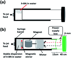
We have explored using the VFD to form h-BN scrolls from h-BN in water under continuous flow mode of operation in the device, establishing ca. 10% yield conversion for a single pass through the microfluidic platform. For this, and also for simple exfoliation (no scroll formation) we used commercially available h-BN comprised of multiple layers. Effective processing of h-BN required reconfiguring the typical continuous flow mode of operation of the VFD, to overcome any build-up of material on the walls of the rapidly rotating tube during the processing. Typically the VFD operates at a tilt angle of +45°, with the liquid whirling up and out of the tube, and this is the optimum angle for a plethora of applications of the device.12,27 When the tube is now spun in an inverted continuous flow mode, at a tilt angle of −45° relative to the horizontal position, the yield of scrolls and exfoliated h-BN increases, with dramatically reduced processing times. Moreover, the processing is effective in water, as a benign solvent, in place of NMP which was used in the SDP for exfoliating the 2D material. A suspension of h-BN in water was delivered into the VFD using an in house built magnetically stirred syringe, Fig. 2.28,29
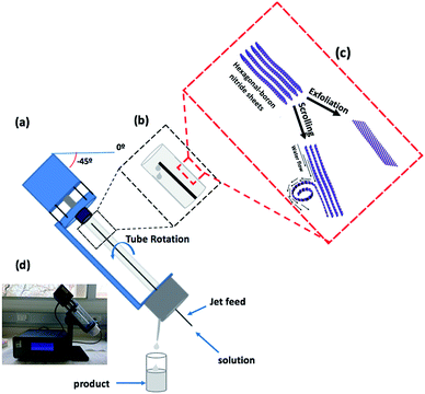
A detailed understanding of the mechanism of graphene scroll formation from graphite in an SDP has been developed,11 and it may be applicable to the formation of h-BN scrolls in a VFD. The formation of graphene scrolls is driven by the energetically favoured intra-layer stacking once an edge of a graphene sheet is lifted up and curled to strike its own upper surface.11 Both the SDP and VFD are microfluidic platforms, generating dynamic thin films, the thickness of which depends on the rotational speeds of the disc or tube respectively, along with other factors. The VFD is a more versatile platform and can be operated at different tilt angles, which is usually not the case for the SDP.26 In addition, the VFD can operate under continuous flow as well as under the confined mode, where a finite volume of liquid is placed in the rapidly rotating tube. The shear stress here is sufficient to exfoliate graphene from graphite, and also single h-BN sheets from h-BN flakes, albeit in low yield, and without forming scrolls.30 The research here used a 10 mm OD glass tube inclined at +45°, operating under confined mode, using NMP as the solvent.30 Indeed, this was reported in the first paper on the VFD, and since then there have been a number of applications, including slicing carbon-nanotubes.31,32 In the present study the exfoliation of h-BN has been dramatically increased, now under continuous flow, achieving ca. 22% yield for a single pass through the microfluidic platform, using only water as the solvent. The VFD of choice housed a borosilicate glass tube (O.D. diameter 20 mm, I.D. diameter 17.5 mm, 19.5 cm long), open at one end, which was rotated at high speed (between 0–9k rpm) and orientated down to −45° tilt angle relative to the horizontal position, Fig. 1.30,31,33,34 Herein we report both the use of the VFD to primarily exfoliate h-BN with a small amount of h-BN scrolls or vice versa, depending on the operating parameters of the device which were systematically explored, along with concentration of the material and the choice of solvent.
Experiments
Materials
Hexagonal boron nitride (h-BN) powder flakes ≈ 1 μm in diameter were obtained from Sigma Aldrich and were dispersed in Milli-Q water for all experiments.Delivery of a suspension of h-BN into the VFD
A suspension of h-BN in Milli-Q water was delivered at a controlled flow rate as close as possible to the hemi-spherical base of the rapidly rotating tube. This was achieved using an in house developed syringe with a motor housed in the plunger, for magnetically stirring the solution during delivery into the VFD tube, as illustrated in Fig. 2.28,29Fabrication of h-BN scrolls
Prior to continuous flow processing the h-BN was dispersed in Milli-Q water using sonication (10 min, 6 kHz). The solution was then transferred to the magnetically stirred syringe and a rapidly stirred dispersion of h-BN in water (0.1 mg mL−1) was delivered via a jet feed to the base of the rotating glass tube in the VFD. The tube was inclined at −45° and spun at a pre-determined speed, of which 6k rpm was found to be optimal. The flow rate was varied and 0.3 mL min−1 was found to be optimal.Exfoliation of h-BN
In the same way, h-BN dispersed in water (0.3 mg mL−1) was delivered via a jet feed to the base of the rotating glass tube in the VFD. The tube was tilted at −45° and spun at a pre-determined speed, of which 6k rpm was found to be optimal. The flow rate was varied and 0.75 mL min−1 was found to be optimal.Characterization
The h-BN scrolls and exfoliated h-BN were characterized using scanning electron microscopy (SEM-Inspect FEI F50 SEM), atomic force microscopy (AFM – Nanoscope 8.10 tapping mode), Raman spectroscopy (WiTec Alpha 300R λexc = 532 nm), XRD (Bruker D8 ADVANCE ECO, Co-Kα, λ = 1.7889 Å), ATR-FTIR PerkinElmer Frontier, transmission electron microscopy (TEM) (FEI Tecnai F20 operated at 200 kV) and simultaneous thermal analysis (PerkinElmer STA 8000).Results and discussion
The VFD is a flexible thin film processing platform, with a number of operating parameters (rotational speed, tilt angle (θ) and flow rate) to be systematically explored, along with the choice of solvent and concentration, as in the present case for exfoliating and scrolling h-BN. VFD processing usually explores tilt angles between 0° to 90°, with +45° typically giving the optimal outcome.35 However, in the present study this angle resulted in material adhering to the wall of the glass tube, with a small amount exiting in the liquid at the top of the tube, as h-BN scrolls and exfoliated h-BN, ca. 1% yield. We hypothesised that centrifugal force was holding the material against the wall of the tube, and that by inverting the tilt angle (<0°), gravitational pull in the direction of the flow of the liquid would facilitate the material exiting the tube. To this end we explored the effect of 45°, 20°, 0°, −20° and −45° tilt angles, Table S1.† Interestingly even at the higher speeds where there is greater centrifugal force in the tube, −45° tilt angle was effective in circumventing the build-up of material in the tube, Fig. S5.† Indeed, at −45° tilt angle there was a dramatic increase in yield of the scrolls and exfoliated material. Interesting the residence time of liquid in the tube at −45° was shorter (>2 min) than +45° for the same rotation speeds and flow rates, as expected from the gravitational pull down the tube.The processing was then optimised by systematically varying the other control parameters, at a −45° tilt angle. This involved the use of water as a solvent, with other solvents, namely NMP, IPA, DMF and toluene, affording little or no h-BN scrolls and exfoliated h-BN. The same was also found for using combinations of solvents, at a 1![[thin space (1/6-em)]](https://www.rsc.org/images/entities/char_2009.gif) :
:![[thin space (1/6-em)]](https://www.rsc.org/images/entities/char_2009.gif) 1 ratio, including NMP with water, DMF with toluene, water with toluene, and IPA with water. Accordingly, water was deemed to be the optimal solvent for subsequent experiments, for then varying the rotation speed of the glass tube in the VFD, flow rate, and concentration of h-BN. We found that 6k rpm gave the highest conversion of h-BN into scrolls (ca. 10%), and rotational speeds of 4k rpm, 5k rpm, 7k rpm and 8k rpm gave low yields of the scrolls. A flow rate of 0.3 mL min−1 was then determined as optimal relative to flow rates of 0.1 mL min−1, 0.5 mL min−1, 0.7 mL min−1 and 1 mL min−1. These parameters were then set, for then varying the remaining two parameters. Other concentrations of h-BN in water were also investigated for all of the flow rates, at 0.1 mg mL−1, 0.2 mg mL−1, 0.3 mg mL−1, 0.5 mg mL−1, 0.7 mg mL−1 and 1.0 mg mL−1. Of these, 0.1 mg mL−1 gave the optimal yield of h-BN scrolls as 10% with some exfoliation (flow rate of 0.3 mL min−1), with other concentrations resulting in lower yields across all the flow rates. Thus, the overall optimum operating parameters for generating scrolls in a single pass in the VFD are a concentration of 0.1 mg mL−1, 0.3 mL min−1 flow rate and 6k rpm rotational speed, using water as the solvent.
1 ratio, including NMP with water, DMF with toluene, water with toluene, and IPA with water. Accordingly, water was deemed to be the optimal solvent for subsequent experiments, for then varying the rotation speed of the glass tube in the VFD, flow rate, and concentration of h-BN. We found that 6k rpm gave the highest conversion of h-BN into scrolls (ca. 10%), and rotational speeds of 4k rpm, 5k rpm, 7k rpm and 8k rpm gave low yields of the scrolls. A flow rate of 0.3 mL min−1 was then determined as optimal relative to flow rates of 0.1 mL min−1, 0.5 mL min−1, 0.7 mL min−1 and 1 mL min−1. These parameters were then set, for then varying the remaining two parameters. Other concentrations of h-BN in water were also investigated for all of the flow rates, at 0.1 mg mL−1, 0.2 mg mL−1, 0.3 mg mL−1, 0.5 mg mL−1, 0.7 mg mL−1 and 1.0 mg mL−1. Of these, 0.1 mg mL−1 gave the optimal yield of h-BN scrolls as 10% with some exfoliation (flow rate of 0.3 mL min−1), with other concentrations resulting in lower yields across all the flow rates. Thus, the overall optimum operating parameters for generating scrolls in a single pass in the VFD are a concentration of 0.1 mg mL−1, 0.3 mL min−1 flow rate and 6k rpm rotational speed, using water as the solvent.
Using the same strategy, we optimised the conditions for exfoliating h-BN, systematically exploring tilt angle, rotational speed, flow rate and concentration in different solvents. The highest yield of exfoliated h-BN was in water, 6k rpm rotational speed, tilt angle −45°, 0.3 mg mL−1 concentration and 0.75 mL min−1 flow rate. Thus, a higher concentration of h-BN and a higher flow rate, at the same tilt angle and rotational speed, favours exfoliation over scroll formation. Changing the flow rate and concentration will alter the complex fluidic dynamics in the VFD, the very nature of which is currently being explored.
The origin of this presumably relates to subtle changes in the expected complex fluid dynamics in changing these parameters.35,36
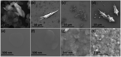
Fig. 3(a) is an SEM image of the as received h-BN flakes for comparison with VFD processed material. Fig. 3(b–d) and S1† are SEM images showing h-BN scrolls formed during the VFD processing (single pass) at the optimised conditions (10% conversion of h-BN to scrolls), with the sample prepared by drop casting the supernatant solution onto a silicon wafer, after centrifugation to remove unprocessed flakes (RCF = 1180×g). They are representative images from different samples. The scrolls range in length, up to ca. 20 μm, which is greater than the cross-section dimensions of the flakes from which they were generated. This suggests that the scrolling process for the long scrolls is not simply single h-BN sheets exfoliated, one at a time, but that there is intertwining of sheets with onset of the formation of the scrolls.
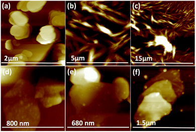
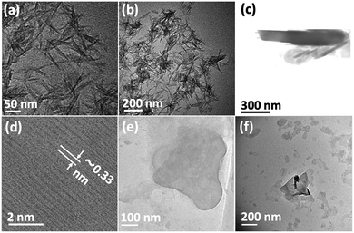
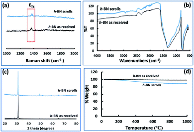
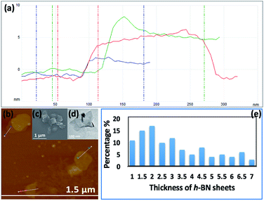
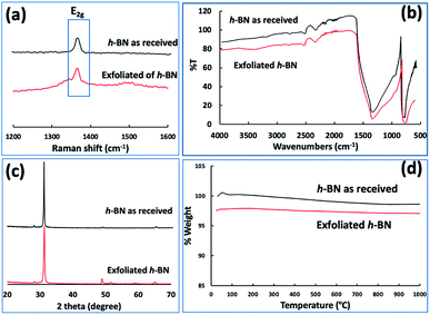
Fig. 3(e–h) and S2† are SEM images of exfoliated h-BN drop cast on silicon wafers for the supernatant after centrifugation to remove unprocessed flakes (RCF = 1180×g). They are representative images from different samples. AFM was also used to investigate the nature of the materials after VFD processing, using the same workup of the solution and drop casting. The AFM image in Fig. 4(a) is for as received material with the dimensions of the particles consistent with the dimensions of the h-BN flakes determined using SEM. The AFM images in Fig. 4(b, c) and S3(a–d)† show the scrolls, with the length of the scrolls longer than the cross section of the starting material, as determined using SEM. Importantly the AFM images establish that the height of the h-BN scrolls vary from 10 nm to 67 nm, from counting ∼100 h-BN scrolls, Fig. 5. AFM images of exfoliated h-BN established the thickness of the h-BN sheets after VFD processing as ca. 2 nm, Fig. 4(d–f) and S3(e, f),† determined from counting >100 sheets, Fig. 8. TEM was also used to further understand the nature of the processed material. Such images in Fig. 6(a–c) and S4† confirmed the shape of the h-BN scrolls formed in the VFD. Fig. 6(d) is a high – resolution TEM image which established the inter-planer spacing between successive turns in the h-BN scrolls as 0.33 nm, which is at the van der Waals limit, as in h-BN itself.11 Fig. 6(e and f) are TEM images of exfoliated h-BN, which are also in agreement with SEM and AFM images. Raman spectra of h-BN has one peak for the B–N E2g symmetry mode at 1368 cm−1. After VFD processing at the optimum conditions, this shifts slightly to higher frequency at 1371 cm−1, Fig. 7(a), which is in accord with stress imparted in the h-BN layer on rolling up BN sheets.37–39 The Raman spectrum of exfoliated h-BN also has a peak for the B–N E2g symmetry mode at 1367 cm−1, Fig. 9(a).40–42 The XRD patterns for both the as received h-BN and h-BN scrolls have the same 2θ peaks at 31.2 (002), 48.6 (100), 51.2 (101), 59.5 (102) and 64.8 (004), which corresponding to the crystallographic planes of h-BN.43 However, the XRD for the h-BN scrolls has higher intensity for the (100, 101, 102) peaks, compared to main peaks (002), Fig. 7(c).44 In addition, XRD of exfoliated h-BN has the same peaks as bulk material, with a change in ratio of the intensity of the (100), (101) and (102) peaks relative to the (002) peak which is informative for determining the presence of mono- and few-layered of h-BN, Fig. 9(c).30,45 The reason for this is a reduction in the number of successive h-BN layers after processing, in forming h-BN scrolls at the van der Waals limit, or exfoliating to a limited number of h-BN sheets, with the main peak at 2θ 31.2 (002), corresponds to a d spacing of 0.33 nm. ATR-FTIR spectra for as received h-BN, h-BN scrolls and exfoliated h-BN have the expected broad peaks for B–N stretching and B–N–B bending vibrations, at 1348 cm−1 and 768 cm−1 respectively.43 However, the ATR-FTIR spectra for h-BN scrolls and exfoliated h-BN have a broad peak at 3400 cm−1 which is assignable to water, presumably confined in the h-BN scrolls and intercalated respectively, Fig. 7(b) and 9(b).41,46 Consistent with this are the results of thermo gravimetric analysis (TGA) for h-BN scrolls, Fig. 7(d), which shows a weight loss starting at ca. 205 °C. This continues as the temperature further increases, with the overall weight loss for the h-BN scrolls ca. 10% which is likely to arise from loss of residual water inside the scrolls prior to heating.47 The confinement of water in the scrolls is noteworthy in considering the potential use of the material for gas storage.21,48 TGA for exfoliated h-BN shows no weight loss for increasing temperature, Fig. 9(d).47
 | ||
| Fig. 5 (a) AFM height of three representative h-BN scrolls. (b) AFM image of drop cast scrolls, for the supernatant and the work up summarized in Fig. 4. (c) TEM image for a h-BN scroll after drop cast onto a grid. (d) SEM images of a h-BN scroll after drop cast on a silicon wafer. (e) Count of h-BN scrolls with different diameters (from AFM images). | ||
Conclusions
h-BN scrolls and exfoliated h-BN have been selectively prepared in water in the VFD, in the absence of harsh chemicals. The yield of each material was dramatically improved by operating at a tilt angle of −45°. This is in contrast to a myriad of other applications of the VFD where the tilt angle is optimal at +45°. The residence time of the liquid entering the VFD tube and exiting at the open end is >2 min. This is in contrast to the ca. 6 minutes residence time for the conventional +45° tilt angle of the tube for identical rotation speeds and flow rates. The ability to fabricate h-BN scrolls and exfoliated h-BN in water in a VFD under continuous flow conditions is without precedent. They are formed in the absence of surfactants and harsh chemicals and the overall processing is high in green chemistry metrics. As to scalability of the processing we prepared 5 mg and 72 mg in one run over 24 hours of h-BN scrolls and exfoliated h-BN respectively. The low amount for the scrolls is because the optimal concentration and flow rate are much less than for fabricating exfoliated sheets, under the same tilt angle and rotational speed. This difference in selectivity reflects the expected changes in the complex fluid dynamics as flow rate and concentration changes. The exfoliation process established is without reduction of the lateral dimensions of the h-BN sheets, i.e. without fragmentation, and presumably this also holds for the formation of the scrolls.Conflicts of interest
There are no conflicts to declare.Acknowledgements
The authors gratefully acknowledge financial support from the Iraq Government, Ministry of Higher Education and Scientific research, and the Australian Research Council and the Government of South Australia. The Australian Microscopy & Microanalysis Research Facility (AMMRF) and the Australian National Fabrication Facility (ANFF) at the South Australian nodes of the AMMRF and ANFF under The National Collaborative Research Infrastructure Strategy are acknowledged, as is Dr Jason Gascooke for assistance with SEM imaging.Notes and references
- Y. Shi, C. Hamsen, X. Jia, K. K. Kim, A. Reina, M. Hofmann, A. L. Hsu, K. Zhang, H. Li, Z.-Y. Juang, M. S. Dresselhaus, L.-J. Li and J. Kong, Nano Lett., 2010, 10, 4134–4139 CrossRef CAS.
- V. V. Pokropivny, V. V. Skorokhod, G. Oleynik, A. V. Kurdyumov, T. S. Bartnitskaya, A. Pokropivny, A. G. Sisonyuk and D. M. Sheichenko, Boron Nitride Analogs of Fullerenes (the Fulborenes), Nanotubes, and Fullerites (the Fulborenites), 2000 Search PubMed.
- H. Wu, X. Fan and J.-L. Kuo, Int. J. Hydrogen Energy, 2012, 37, 14336–14342 CrossRef CAS.
- W.-Q. Han, Nanotechnologies for the Life Sciences, 2008, vol. 41, pp. 1–60 Search PubMed.
- K. Watanabe, T. Taniguchi and H. Kanda, Nat. Mater., 2004, 3, 404 CrossRef CAS.
- K. Watanabe, T. Taniguchi, T. Niiyama, K. Miya and M. Taniguchi, Nat. Photonics, 2009, 3, 591 CrossRef CAS.
- Y. Kubota, K. Watanabe, O. Tsuda and T. Taniguchi, Science, 2007, 317, 932–934 CrossRef CAS.
- W.-Q. Han, L. Wu, Y. Zhu, K. Watanabe and T. Taniguchi, Appl. Phys. Lett., 2008, 93, 223103 CrossRef.
- E. Perim and D. S. Galvao, Nanotechnology, 2009, 20, 335702 CrossRef.
- C. F. Woellner, L. D. Machado, P. A. S. Autreto, J. M. de Sousa and D. S. Galvao, Phys. Chem. Chem. Phys., 2018, 20, 4911–4916 RSC.
- X. Chen, R. A. Boulos, J. F. Dobson and C. L. Raston, Nanoscale, 2013, 5, 498–502 RSC.
- T. M. D. Alharbi, D. Harvey, I. K. Alsulami, N. Dehbari, X. Duan, R. N. Lamb, W. D. Lawrance and C. L. Raston, Carbon, 2018, 137, 419–424 CrossRef CAS.
- C. A. Amadei, I. Y. Stein, G. J. Silverberg, B. L. Wardle and C. D. Vecitis, Nanoscale, 2016, 8, 6783–6791 RSC.
- D. Y. Hwang and D. H. Suh, Nanoscale, 2014, 6, 5686–5690 RSC.
- E. Perim, L. D. Machado and D. S. Galvao, Frontiers in Materials, 2014, 1, 31 CrossRef.
- L. Chu, Q. Xue, T. Zhang and C. Ling, J. Phys. Chem. C, 2011, 115, 15217–15224 CrossRef CAS.
- N. Ding, X. Chen, C.-M. L. Wu and H. Li, Phys. Chem. Chem. Phys., 2013, 15, 10767–10776 RSC.
- Q. Lin, X. Zou, G. Zhou, R. Liu, J. Wu, J. Li and W. Duan, Phys. Chem. Chem. Phys., 2011, 13, 12225–12230 RSC.
- S. K. Kisku and S. K. Swain, J. Am. Ceram. Soc., 2012, 95, 2753–2757 CrossRef CAS.
- Q. Weng, X. Wang, X. Wang, Y. Bando and D. Golberg, Chem. Soc. Rev., 2016, 45, 3989–4012 RSC.
- Q. Weng, X. Wang, C. Zhi, Y. Bando and D. Golberg, ACS Nano, 2013, 7, 1558–1565 CrossRef CAS.
- A. L. M. Reddy, A. E. Tanur and G. C. Walker, Int. J. Hydrogen Energy, 2010, 35, 4138–4143 CrossRef CAS.
- A. Hassani, M. T. H. Mosavian, A. Ahmadpour and N. Farhadian, J. Nat. Gas Sci. Eng., 2017, 46, 265–274 CrossRef CAS.
- Y. Lin and J. W. Connell, Nanoscale, 2012, 4, 6908–6939 RSC.
- T. Fujigaya and N. Nakashima, Polym. J., 2008, 40, 577–589 CrossRef CAS.
- K. Vimalanathan and C. L. Raston, Adv. Mater. Technol., 2017, 2, 1600298 CrossRef.
- I. K. Alsulami, T. M. Alharbi, D. P. Harvey, C. T. Gibson and C. L. Raston, Chem. Commun., 2018, 54, 7896–7899 RSC.
- A. H. Mohammed Al-antaki, X. Luo, A. Duan, R. N. Lamb, E. Eroglu, W. Hutchison, Y.-C. Zou, J. Zou and C. L. Raston, RSC Adv., 2018, 8, 40829–40835 RSC.
- X. Luo, A. H. M. Al-Antaki, K. Vimalanathan, J. Moffatt, K. Zheng, Y. Zou, J. Zou, X. Duan, R. N. Lamb, S. Wang, Q. Li, W. Zhang and C. L. Raston, React. Chem. Eng., 2018, 3, 164–170 RSC.
- X. Chen, J. F. Dobson and C. L. Raston, Chem. Commun., 2012, 48, 3703–3705 RSC.
- T. M. D. Alharbi, K. Vimalanathan, W. D. Lawrance and C. L. Raston, Carbon, 2018, 140, 428–432 CrossRef CAS.
- K. Vimalanathan, J. R. Gascooke, I. Suarez-Martinez, N. A. Marks, H. Kumari, C. J. Garvey, J. L. Atwood, W. D. Lawrance and C. L. Raston, Sci. Rep., 2016, 6, 22865 CrossRef CAS.
- J. Britton, J. M. Chalker and C. L. Raston, Chem.–Eur. J., 2015, 21, 10660–10665 CrossRef CAS.
- M. N. Gandy, C. L. Raston and K. A. Stubbs, Org. Biomol. Chem., 2014, 12, 4594–4597 RSC.
- J. Britton, K. A. Stubbs, G. A. Weiss and C. L. Raston, Chem.–Eur. J., 2017, 23, 13270–13278 CrossRef CAS.
- J. Britton, S. B. Dalziel and C. L. J. G. C. Raston, Green Chem., 2016, 18, 2193–2200 RSC.
- D. H. Suh, Nanoscale, 2014, 6, 5686–5690 RSC.
- S. Reich, A. Ferrari, R. Arenal, A. Loiseau, I. Bello and J. Robertson, Phys. Rev. B: Condens. Matter Mater. Phys., 2005, 71, 205201 CrossRef.
- L. Song, L. Ci, H. Lu, P. B. Sorokin, C. Jin, J. Ni, A. G. Kvashnin, D. G. Kvashnin, J. Lou and B. I. Yakobson, Nano Lett., 2010, 10, 3209–3215 CrossRef CAS.
- Y. Lin, C. E. Bunker, K. A. S. Fernando and J. W. Connell, ACS Appl. Mater. Interfaces, 2012, 4, 1110–1117 CrossRef CAS.
- A. Nag, K. Raidongia, K. P. S. S. Hembram, R. Datta, U. V. Waghmare and C. N. R. Rao, ACS Nano, 2010, 4, 1539–1544 CrossRef CAS.
- X. Wang, A. Pakdel, J. Zhang, Q. Weng, T. Zhai, C. Zhi, D. Golberg and Y. Bando, Nanoscale Res. Lett., 2012, 7, 662 CrossRef.
- X. Hou, M. Wang, L. Fu, Y. Chen, N. Jiang, C.-T. Lin, Z. Wang and J. Yu, Nanoscale, 2018, 10, 13004–13010 RSC.
- S. Yuan, B. Toury, C. Journet and A. Brioude, Nanoscale, 2014, 6, 7838–7841 RSC.
- D. Fan, J. Feng, J. Liu, T. Gao, Z. Ye, M. Chen and X. Lv, Ceram. Int., 2016, 42, 7155–7163 CrossRef CAS.
- C. Gautam, C. S. Tiwary, S. Jose, G. Brunetto, S. Ozden, S. Vinod, P. Raghavan, S. Biradar, D. S. Galvao and P. M. Ajayan, ACS Nano, 2015, 9, 12088–12095 CrossRef CAS.
- J. Hou, G. Li, N. Yang, L. Qin, M. E. Grami, Q. Zhang, N. Wang and X. Qu, RSC Adv., 2014, 4, 44282–44290 RSC.
- T. Oku, Energies, 2014, 8, 319–337 CrossRef.
Footnote |
| † Electronic supplementary information (ESI) available: Experimental details and characterisation results (Fig. S1–S6). See DOI: 10.1039/c9ra03970h |
| This journal is © The Royal Society of Chemistry 2019 |

