 Open Access Article
Microgrooved collagen-based corneal scaffold for promoting collective cell migration and antifibrosis
Sijia Xiongabc,
Huichang Gao*d,
Lanfeng Qinbce,
Yongguang Jia ab,
Meng Gao
 ab and
Li Ren
 *abf
*abf
aSchool of Materials Science and Engineering, South China University of Technology, Guangzhou 510641, China. E-mail: psliren@scut.edu.cn
bNational Engineering Research Centre for Tissue Restoration and Reconstruction, Guangzhou 510006, China
cGuangdong Province Key Laboratory of Biomedical Engineering, South China University of Technology, Guangzhou 510006, China
dSchool of Medicine, South China University of Technology, Guangzhou 510006, China
eSchool of Biology and Biological Engineering, South China University of Technology, Guangzhou 510006, China. E-mail: mchcgao@scut.edu.cn
fSino-Singapore International Joint Research Institute, Guangzhou 510555, China
First published on 18th September 2019
Abstract
Collagen is a promising material for corneal tissue engineering. The surface topography of collagen is critical for cornea reconstruction and regeneration. Herein, we fabricated collagen films with microgrooved surface to investigate the effect of collagen film topography on corneal cell migration and antifibrosis. We found that the patterned films with microscale grooves could greatly affect the orientation, proliferation, migration, and gene expression of rabbit corneal epithelial cells and keratocytes. Compared with the natural cornea, the optimized collagen films with microgroove pattern show similar swelling performance, optical clarity, and biodegradability, which could efficiently promote the epithelial cell migration, accelerate wound healing process, and inhibit the fibrosis of keratocytes. These results suggest that collagen films with microgroove pattern are promising in corneal tissue engineering.
Introduction
As the outermost layer of the eye, the cornea is susceptible to physical damage, chemical burns, and bacterial or fungal infection,1,2 which would lead to a visual impairment or blindness. To date, corneal transplantation is the only approach to treat corneal blindness in clinic, but the shortage of cornea donors calls for the development of corneal tissue engineering.3,4 The ideal tissue engineering scaffold should possess immunologic tolerance, good optical clarity, and suitable mechanical properties.5 There are a wide variety of tissues or biomaterials used for corneal tissue engineering, such as acellular corneal stroma,6 amniotic membrane,7 silk fibroin,8 and collagen.9 Their characteristics have been reviewed by some studies.10,11 As the principal component of corneal stroma, collagen has similar physiological and immunological properties compared with natural cornea, and its mechanical properties could easily be promoted via crosslinking or compositing. Collagen become one of the most promising material used in corneal tissue engineering.12 However, the previous studies showed that a stromal opacity or haze can occur after corneal transplantation, which may be due to the myofibroblast transformation of keratocytes.13,14 In addition, a slow migration rate of corneal epithelial cells may also inhibit the regeneration of corneal epithelial tissue. Therefore, it's critical to develop cornea substitutes which can inhibit keratocyte differentiation and accelerate corneal epithelial cell migration.The basement membrane between the cornea epithelium and stroma has been found to have macro- and nanoscale topography features, providing unique sites for cell–substrate interactions.15–17 In addition, the corneal stroma has highly-organized structure with aligned collagen fibers and cells, which determines cornea's transparency.18 Therefore, it's important to introduce topographic cues into corneal tissue engineering for mimicking the microenvironment of cells. Previous studies have shown that the engineering substrate topography can significantly influence cell shape,19,20 adhesion,21–23 migration,24 proliferation,25–27 and differentiation.28,29 For corneal cells, their behaviors are also regulated by surface topography.30,31 For example, the extracellular matrix expression of keratocytes could be regulated to recreate the structure of the stroma.32,33 In addition, some studies have broached that patterned surfaces can promote the migration of corneal epithelial cells.34,35 Therefore, the topography–cell interaction could be combined with corneal tissue engineering to develop a micropatterned scaffold that is able to regulate cells. Such strategy may reduce keratocyte differentiation and accelerate corneal epithelial cell migration, which not only helps regulate corneal cell behavior but also mimic the in vivo microenvironment of the native cornea.36In this work, collagen was chosen as a scaffold material, and engineering microscale groove structure was applied to fabricated a corneal tissue engineering scaffold, aiming to accelerate corneal epithelial cell migration and reduce keratocyte differentiation (Fig. 1). The influences of surface topography on swelling capacity, optical clarity, and degradation rate of collagen films were studied. Also, response of rabbit corneal epithelial cells (CECs) and keratocytes, including orientation, proliferation, migration, and differentiation, on the micropatterned surface were observed. Overall, the study offers an insight into cell–topography interaction and the use of surface topography for corneal issue engineering.
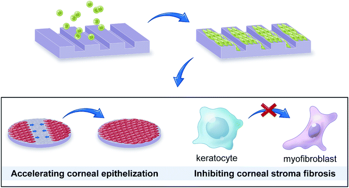 | ||
| Fig. 1 Microgrooved collagen films was fabricated to explore its application potential for corneal tissue engineering. | ||
Experimental
Materials
Type I collagen was extracted from bovine tendon. 1-(3-Dimethylaminopropyl)-3-ethylcarbodiimide hydrochloride (EDC) and N-hydroxysuccinimide (NHS) were supplied by Sigma-Aldrich Corporation (Germany). Hydrochloric acid (HCl), acetone and isopropanol were obtained from Guanghua Chemical Factory (China). Deionized water was prepared by the water purification system (Millipore S. A. S, France). NR21-20000P negative photoresist was provided by Futurrex company (USA). The poly(dimethylsiloxane) prepolymer, sylgard 184, was purchased from Dow Corning (USA). Collagenase type I was provided from Solarbio company (China). Phosphate buffered saline (PBS, pH = 7.4), Dulbecco's modified Eagle medium (DMEM), fetal bovine serum (FBS) and other cell-culture related reagents were all bought from Gibco (USA). Cell Counting Kit-8 (CCK-8) was provided from Dojindo Laboratories (Japan). F-Actin Labeling Kit and 4′,6-diamidino-2-phenylindole (DAPI) were both from AAT (USA). Recombinant human TGF-β1 was provided by PeproTech (USA). HiPure Total RNA Micro Kit was purchased from Magen (China), and reverse transcription reagents kit from Takara (Japan). BCA Protein Assay Kit was bought from Beyotime (China). The rabbit corneal epithelial cells (CECs) and keratocytes were provided by Rochen Pharma (China).PDMS template preparation
A method combining soft lithography with solution casting were used to fabricate microgrooved collagen films. Fig. 2 showed the main steps. Firstly, soft lithography was employed to prepare a poly(dimethylsiloxane) (PDMS) template (Fig. 2a). In brief, the patterned silicon wafer was fabricated using traditional photolithography techniques. Groove patterns with different groove width (25 μm, 50 μm, 100 μm), same ridge width (200 μm), and depth (50 μm) was designed using Computer Aided Design (Autodesk Inc.) to product a mask. Then flat silicon wafers coated with negative photoresist was baked at 80 °C for 10 min and 150 °C for 5 min. Then the photoresist was exposed to UV light through the mask, and the silicon wafers with expected patterns were produced after development in RD6 developer solution. Subsequently, a mixture of PDMS prepolymer and curing agent (10![[thin space (1/6-em)]](https://www.rsc.org/images/entities/char_2009.gif) :
:![[thin space (1/6-em)]](https://www.rsc.org/images/entities/char_2009.gif) 1 w/w) was poured onto the silicon wafer and cured at 60 °C for 4 h, and a PDMS template was obtained.
1 w/w) was poured onto the silicon wafer and cured at 60 °C for 4 h, and a PDMS template was obtained.
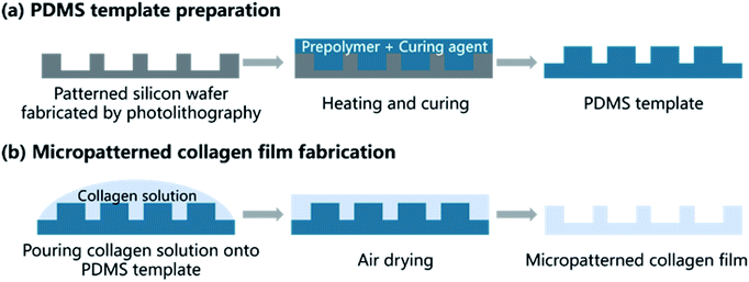 | ||
| Fig. 2 Schematic illustration of patterned collagen film fabrication process shows the two main steps: preparation of PDMS and fabrication of micropatterned collagen films. | ||
Micropatterned film fabrication
The microgrooved collagen film was fabricated with the method of solvent casting (Fig. 2b). Briefly, collagen solution was prepared by dissolving type I collagen in 0.01 M HCl solution at 4 °C. Then cross-linking agent EDC and the catalyst NHS were added to the collagen solution according to a mass ratio of EDC![[thin space (1/6-em)]](https://www.rsc.org/images/entities/char_2009.gif) :
:![[thin space (1/6-em)]](https://www.rsc.org/images/entities/char_2009.gif) NHS
NHS![[thin space (1/6-em)]](https://www.rsc.org/images/entities/char_2009.gif) :
:![[thin space (1/6-em)]](https://www.rsc.org/images/entities/char_2009.gif) collagen = 1
collagen = 1![[thin space (1/6-em)]](https://www.rsc.org/images/entities/char_2009.gif) :
:![[thin space (1/6-em)]](https://www.rsc.org/images/entities/char_2009.gif) 1
1![[thin space (1/6-em)]](https://www.rsc.org/images/entities/char_2009.gif) :
:![[thin space (1/6-em)]](https://www.rsc.org/images/entities/char_2009.gif) 6, and the mixture was stirred by an electromagnetic stirrer (SP-18, MIULAB, China) at 4 °C to thoroughly mix and cross-link. Next, the mixture was casted onto a container, the bottom of which was covered by the micropatterned PDMS template. After air dried, the collagen films were peeled off from the template, and micropatterned films were obtained. Unpatterned film was prepared with the same method, expect that the PDMS template was unpatterned. The morphology of microgrooved collagen films was observed.
6, and the mixture was stirred by an electromagnetic stirrer (SP-18, MIULAB, China) at 4 °C to thoroughly mix and cross-link. Next, the mixture was casted onto a container, the bottom of which was covered by the micropatterned PDMS template. After air dried, the collagen films were peeled off from the template, and micropatterned films were obtained. Unpatterned film was prepared with the same method, expect that the PDMS template was unpatterned. The morphology of microgrooved collagen films was observed.
Swelling test
To characterize water absorption ability of micropatterned collagen films, swelling test was conducted. In brief, dry collagen films were weighed and then immersed in PBS (pH = 7.4). At regular time intervals, swollen collagen films were taken out and blotted with filter paper to remove the superficial water, and subsequently the weight of the collagen films were measured. The water absorption of films is computed from the following equation:| Water absorption = (Mt − M0)/Mt × 100% |
Light transmittance
In order to study optical performance of micropatterned collagen films, the light transmittance of the films was measured using an ultraviolet-visible spectro-photometer (Shanghai UNICO, China). Briefly, collagen films were immersed in PBS solution (pH = 7.4) to water equilibrium and then scanned in the range of 400–700 nm at room temperature.In vitro degradation
In vitro degradation test was performed to evaluate the degradation rate of films. In brief, after weighed, collagen films fully equilibrated with water were placed in 5 ml PBS which contains collagenase type I (5 U ml−1). Then, the system was incubated at 37 °C and the weight of films was recorded with time until films degraded completely. The residual mass of films was normalized according the following formula,| Residual mass (%) = Wt/W0 × 100% |
Cell culture and seeding
CECs and keratocytes were cultured in DMEM medium supplemented with 10% FBS. All the cells were kept at 5% CO2, 37 °C. After sterilized by ultraviolet radiation, collagen films were placed in 24-well plates and fixed with sterilized rubber rings. Then, collagen films were rinsed by PBS for three times to remove residual hydrochloric acid. Finally, cells were seeded onto the collagen films and cultured for a set period of time, with medium replaced every 48 h.Cell proliferation assay
CCK-8 was used to assess the proliferation of the CECs and keratocytes on micropatterned collagen films with different groove width. In brief, CECs and keratocytes were seeded onto the surface of collagen films at densities of 1.0 × 10⁴ cells per well. At the prescribed time points (1, 3, 5 d), CCK-8 working solution was added to each well and incubated for 1 h at 37 °C. Subsequently, the supernatant medium was extracted, and its absorbance at 450 nm was measured by a microplate reader (Thermo 3001, Thermo, America) (n = 5).Florescent staining
The morphology and orientation of cells cultured on microgrooved collagen films were studied by florescent staining. In brief, after culture medium removed, cells were washed with PBS, then fixed in 4% paraformaldehyde solution for 15 min at room temperature and subsequently washed with PBS. Next, the cells were permeabilized with 0.1% Triton-X 100 for 15 min and then washed with PBS again. Thereafter, the cells were immersed in F-actin labelling probe for 1 h to stain the actin filaments. After rinsed with PBS for 5 min, DAPI was added to the culture plate for 15 min with two subsequent PBS rinses (5 min per wash). Finally, the morphology of fluorescently stained cells on the micropatterned substrates was observed by a confocal laser scanning microscopy (SP8, Leica, Germany).In vitro would healing assay
To assess the effects of patterned surface on the migration activities of CECs, an in vitro would healing assay was conducted. Briefly, 1 mm-wide titanium strips were placed perpendicularly with axis of grooves onto each film and fixed by rubber rings. The CECs were seeded onto microgrooved collagen films at a density of 5.0 × 10⁴ cells per well. After cells were cultured for 24 hours, the titanium strip was taken out and a 1 mm-wide wound gap was generated. The images of wound gaps on 0, 24 and 48 h were captured using a confocal laser scanning microscopy. Before observation, the cells were incubated with a self-made fluorescent cytoplasm staining dye (a kind of aggregation-induced emission molecule) for 1 h.Cell differentiation
The myofibroblast transformation of keratocytes was explored by real-time polymerase chain reaction (RT-PCR). In brief, keratocytes were seeded onto collagen films and cultured for 3 days. Then 2.5 ng ml−1 recombinant human TGF-β1 was added and cells were cultured for another 3 days. Then RNA was extracted using the HiPure Total RNA Micro Kit following the manufacturer's instructions. Total RNA concentrations were quantified using NanoDrop 2000 (Thermo Scientific, USA). Next, a reverse transcription reagents kit was used to synthesize cDNA. Finally, RT-PCR was achieved using the SYBR green system (Genecopoeia, USA). Amplifications for cDNA samples were carried out at 50 °C for 2 min and at 95 °C for 10 min, followed by 40 cycles at 95 °C for 15 s, 60 °C for 30 s, and 72 °C for 30 s. The following primer sequences were used: GAPDH: forward: 5′-ACTTCGGCATTGTGGAGG-3′; reverse: 5′-GGAGGCAGGGATGATGTTCT-3′; for α-SMA: forward: 5′-CCATGCCATCATGCGTCT-3′; reverse: 5′-GCCATCTCGTTTTCAAAGTCC-3′; for Col1A1: forward: 5′-GCCTGAGCCAGCAGATTGA-3′; reverse: 5′-AGGTTGCCCCAGTGTCCAT-3′; CTGF: forward: 5′-AGGAGTGGGTGTGTGATGAG-3′; reverse: 5′-CCAAATGTGTCTTCCAGTCG-3′. The relative quantification of target genes was normalized to the corresponding value of glyceraldehyde-3-phosphate dehydrogenase (GAPDH) and calculated using the 2−ΔCt method.Western blotting analysis
Keratocytes cultured on collagen films were collected and lysed in reagent containing RIPA buffer and PBST. After cell lysates were centrifuged at 13![[thin space (1/6-em)]](https://www.rsc.org/images/entities/char_2009.gif) 000 rpm for 5 min, the supernatant was collected and the protein was quantified with a BCA Protein Assay Kit, followed by mixture with 25 μl 2× SDS-PAGE loading buffer (100 mM Tris–HCl, pH 6.8, containing 200 mM DTT, 4% SDS, 0.2% BPB, 20% glycerol). After being heated at 95 °C for 5 min, equal amount of protein samples was loaded onto separation gel and stacking gel (1 M Tris, pH 8.8, containing water, 30% acrylamide, 10% SDS, 10% AP, TEMED). Gel electrophoresis was performed at 60 V for 25 min followed by 80 V for 1 h. The proteins were then transferred onto PVDF membrane. The membrane was blocked with 5% non-fat milk in PBSF for 45 min at room temperature and then incubated with a primary antibody for 1 h in room temperature. Before incubating with a goat anti-rabbit IgG or anti-mouse IgG antibody for 30 min, the membranes were washed with PBSF, protein bands were detected by enhanced chemiluminescence according to the manufacturer's instructions and an imaging system.
000 rpm for 5 min, the supernatant was collected and the protein was quantified with a BCA Protein Assay Kit, followed by mixture with 25 μl 2× SDS-PAGE loading buffer (100 mM Tris–HCl, pH 6.8, containing 200 mM DTT, 4% SDS, 0.2% BPB, 20% glycerol). After being heated at 95 °C for 5 min, equal amount of protein samples was loaded onto separation gel and stacking gel (1 M Tris, pH 8.8, containing water, 30% acrylamide, 10% SDS, 10% AP, TEMED). Gel electrophoresis was performed at 60 V for 25 min followed by 80 V for 1 h. The proteins were then transferred onto PVDF membrane. The membrane was blocked with 5% non-fat milk in PBSF for 45 min at room temperature and then incubated with a primary antibody for 1 h in room temperature. Before incubating with a goat anti-rabbit IgG or anti-mouse IgG antibody for 30 min, the membranes were washed with PBSF, protein bands were detected by enhanced chemiluminescence according to the manufacturer's instructions and an imaging system.
Image and statistical analysis
Images were analysed with ImageJ software. A one-way ANOVA was performed to assess the level of significance. Results are expressed as the mean ± standard error, and p < 0.05 was designated as statistically significant.Results and discussion
Fabrication and characterization of microgrooved collagen films
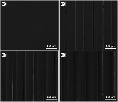
In this study, the microgrooved collagen films were successfully fabricated by the method of combining soft lithography techniques and solvent casting. All three of the patterns have the same ridge width (200 μm) and groove depth (50 μm), and the grooves widths were 25 μm, 50 μm, and 100 μm, respectively. In our study, microgroove was chosen as the micropattern for two reasons. First, the groove structure can mimic the highly-organized structure with aligned collagen fibres for the corneal stroma to a certain degree. Second, the parallel groove topology can guide the directed migration of cells and may be contribute to the epithelialization of corneal epithelial cells.37 In addition, microscale grooves have comparable size with cells and can regulate the behaviour of cell populations.38 For the sake of convenience, we labelled the three patterned collagen films as W25D50 (groove width: 25 μm, depth: 50 μm), W50D50 (groove width: 50 μm, depth: 50 μm) and W100D50 (groove width: 100 μm, depth: 50 μm). The unpatterned collagen film as control group was labelled as Smooth.The morphology of acquired collagen films were evaluated by SEM (Fig. 3). As we can see, the as-prepared samples exhibited clean surface without impurity particles, and the microgroove features including shape and size are in good accordance with the design, indicative of the precise pattern transfer between PDMS template and collagen replica. The SEM image demonstrated that expected topography features with high fidelity were successfully produced on the surface of collagen film, which means that the fabrication method of patterned collagen films used in this study is robust and can be applied to the production of collagen films with various microgrooves. In addition, compared to other microfabrication methods, the way combining soft lithography and solvent casting is relatively inexpensive and more suitable mass production.
Physicochemical properties of collagen films
As corneal tissue engineering scaffold, there are a lot of prerequisites must be met for candidate materials, such as transparency, swelling property, degradation rate and so on.5 To evaluate the feasibility of microgrooved collagen membrane as corneal tissue engineering scaffold, a series of properties of microgrooved collagen films was determined. Appropriate water content of cornea helps to maintain corneal structure and plays an important role in transparency of the cornea.39 The result of swelling test was shown in Fig. 4a. As we can see, the water contents of all four kind of collagen films were about 85%, which is comparable to the value of healthy human cornea and can meet the demand of tissue engineered cornea.40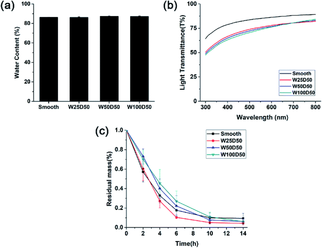 | ||
| Fig. 4 (a) Equilibrium water absorption, (b) visible light transmission and (c) in vitro biodegradation rate in collagenase solution of collagen films. | ||
Besides, there were no significant differences in equilibrium water absorption between patterned collagen films with different groove size and unpatterned collagen films. These results strongly suggested that surface micropatterning had no impact on swelling performance of collagen films. The reason might be that the flat and patterned films have similar internal microstructures and crosslinking density, which determines the property of swelling performance.
One of the most important function of cornea is to transmit incoming light to interior optical element. Therefore, the effect of microgrooves on the transparency of the collagen films was accessed by testing visible light transmission of films. As shown in Fig. 4b, the light transmission of all the films increased with the increase of the wavelength, which is similar to the human cornea. Collagen films with smooth surface have good optical property with the light transmission reaching 90% at 800 nm. After micropatterning, there was a slight decrease in transparency of collagen films, which might result from the increased light scattering induced by patterned surface. These patterned films with different groove width showed similar optical performance, and the light transmission is about 70% at 400 nm, and near 80% at 750 nm. Compared to human cornea whose visible light transmission is about 90%, the patterned collagen films showed an acceptable decrease in transparency. Therefore, the patterned collagen films could satisfy the request of corneal tissue engineering.
A suitable degradation rate is pivotal to the success of corneal tissue engineering. Therefore, the degradation rates of microgrooved collagen films were evaluated with an in vitro degradation assay in collagenase solution, and Fig. 4c showed the relative residual mass of collagen films as a function of time. As we can see, although W100D50 and W50D50 showed slightly lower degradation rate than the other two films at the beginning stage, there was no significant difference in the average degradation rate of different collagen films, and almost all of the collagen films were degraded completely in 14 h. The results indicated that micropatterned collagen films possessed the similar degradation rate with unpatterned films and the process of surface patterning had no significant influence on the degradation of collagen films. The reason might be that the process of surface micropatterning would not change the collagen internal microstructure and chemical activity.
Cell orientation
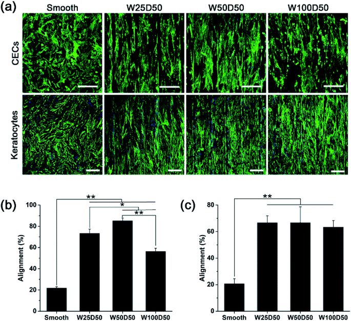
Although large quantities of studies have previously explored the influences of surface topography on corneal cell behaviour.30,41–43 Cell–topography interaction on patterned collagen films has not been revealed and exploited in corneal tissue engineering yet. In this paper, CECs and keratocytes were cultured on patterned collagen films and their responses were observed, hoping to reveal the effect of patterned surface on corneal cells and develop a tissue engineered cornea which has ability to inhibit corneal haze formation and accelerate epithelization.Generally, one of the most noticeable impact of groove patterns on cells is that cells tend to elongate and align with the axis of the grooves, which is also described as contact guidance. To determine cell orientation on the patterned collagen, CECs and keratocytes cultured on collagen films were stained by F-Actin Labelling Kit and DAPI after cultured for 48 h and then observed with a confocal laser scanning microscopy. The image captured were shown in Fig. 5a. As we can see, the population of CECs and keratocytes on patterned collagen films responded strongly and appeared marked alignment along the grooves. Whereas, on flat control, the cells showed a random arrangement. Besides, cells on the microgrooved sample was accompanied by an elongation of cell shape while the cells on planar films retained the original morphology. In order to show the alignment degree of cells intuitionally, the percentages of aligned cells were calculated, which was defined as alignment index. On patterned surface, a cell would be considered aligned with the grooves when the angle between the longest cell axis and the axis of grooves was less than 10°, or it would be considered randomly arranged. As we observed from the statistical results (Fig. 5b and c), the alignment index was significantly increased from 20% on flat control to about 60% on patterned collagen film for both two types of cells. For keratocytes, there was no significant difference for different grooved films with different widths. However, the alignment index of CECs remained about 56% on W100D50 but increased to 73% and 85% on W25D50 and W50D50, respectively.
Despite that cell responses to linear groove pattern depends on many factors, including cell types, feature sizes and physicochemical properties of substrate, the guidance of cell elongation and orientation occurred on numerous cell types seeded various substrates, except for some special cases.44 In addition, although the variation of feature size has shown ability to affect the degree of cell alignment, the effect is not universally observed in any circumstance. In present work, alignment of CECs was shown to be susceptible to groove width, and stronger alignment was observed on 50 μm-wide-grooves. In contrast, keratocytes didn't response to variations of groove width. The result demonstrated again that, for the same surface topography, different cell type would produce different response. In addition, Fraser et al. studied the response of CECs to submicron grooves and found that the alignment of CECs showed no difference on grooves with feature widths.45 These results suggested that CECs on grooves with submicro- or microscale sizes were regulated with different underlying mechanism. For keratocytes, studies of Teixeira et al. showed that percentage of aligned keratocytes remained 70% as the groove pitches increased from 800 to 4000 nm,42 which is constant with our results, indicating that grooves width varying in range of 800 nm to 100 μm didn't have significant influence on degree of cell orientation.
Cell proliferation
As the main component of the cornea stroma, collagen has a good biocompatibility and is beneficial to cell proliferation. The patterned surface on the collagen films may also affect expansion of cells cultured on it, which might be the key factor to corneal tissue engineering. To quantitate the effects of designed groove patterns on proliferation of CECs and keratocytes, cells were seeded on collagen films and then tested by CCK-8 at 1, 3, 5 d. It could be seen from Fig. 6 that both CECs and keratocytes showed normal exponential growth on all collagen films. For CECs, there was no significant difference between cell proliferation rate on patterned collagen films and planar control for the first three days. However, cells on patterned films appeared a little slower proliferation rate than those on planar control at 5 d, especially on W100D50 and W50D50. For keratocytes, cells on patterned collagen films tended to grow more slowly than those on planar control at beginning. Then, cells on W100D50 showed a distinctly lower proliferation rate compared with those on other films, and W50D50 and W25D50 are slightly more suitable for cell proliferation than planar films, but there was no difference between the two kind of grooved films and the smooth control.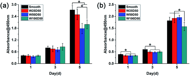 | ||
| Fig. 6 Cell proliferation behaviour measured by CCK-8 assay after culturing (a) CECs and (b) keratocytes on collagen films. | ||
Most reports showed that groove patterns usually result in lower proliferation than flat surface.46,47 The CECs cultured on the collagen films in present work also showed the same trend. Currently, the mechanism of surface topography affecting cell proliferation has not been elucidated yet. However, cell shape has been repeatedly found to influence cell behaviours and control cell life and death.25,48 Thus, it can be hypothesized that surface topography regulates cell proliferation via changing cell shape. For CECs in present work, it is worth notice that the decrease of proliferation rate on patterned collagen films was accompanied by lager number of aligned cells. The restriction to cell spreading and marked change of cell shape might mainly account for the slower proliferation of CECs on microgrooves. For keratocytes, the morphology differences between cells on grooved surface and planar surface were relatively inapparent, and the aligned collective keratocytes was an imitation to highly-organized structure in native stromal tissue. These reasons could explain slightly promotion of proliferation rate of keratocytes on W50D50 and W25D50 but decrease of keratocyte proliferation on W100D50, suggesting that more than one mechanism was involved in cell proliferation on microgrooves with different feature size. The decreased proliferation on W100D50 might be related with the restricted cell spreading on microgrooves. When cultured on narrower grooves, such as W25D50 and W50D50, cells could bridge across the grooves.49 Whereas, grooves of W100D50 are too wide to bridge for keratocytes, which restricted cell spreading and resulted in decrease on cell proliferation. Thus, these results also indicated that different types of cells may have different responses to the same topological microstructure.
Cell migration and healing
It has been found that the migration phase, where cells around the wound migrate to cover the bare part, plays an important role in corneal epithelial wound healing.50,51 Therefore, rapid migration of CECs may accelerate wound healing on corneal epithelium. Previous researches have demonstrated that cell migration on grooved surface would be restricted along the axis of grooves.52,53 In present study, an in vitro wound healing assay was designed to investigate the contact guidance to CECs of patterned films and the effect of surface pattern on the speed of wound healing. Before CECs were seeded onto the films, a titanium strip was placed onto each film perpendicular to the grooves. After 24 h of culture, titanium strips were removed, and distinct wounds with a width of 1 mm were attained. Then the wound healing process was observed. As Fig. 7 shows, compared to the flat control, wound healing process on patterned collagen films were significantly accelerated. After wound healing for 48 h, there was still a gap on the smooth collagen films, but the wound on collagen films with patterned surface had disappeared completely. Among three kinds of patterned collagen films, faster wound healing was seen on narrower grooves. Previous study of Li et al. has shown similar results.54 From the fluorescent images, we could clearly see that the wound borders on topography patterns had become indistinctive since many cells have outpaced their partners and reached to centre at 48 h. More accelerated cells on narrower grooves induced rapider cell migration, indicating the accelerated wound healing mainly owed to the speed-up of individual CECs along the grooves. In addition, the wound healing process is an outcome of cooperation of cell migration and cell proliferation. Therefore, the higher proliferation on W25D50 compared the other two patterned films might also contribute the fastest wound healing. Anyway, the guidance of groove patterns to cell migration indeed accelerated in vitro corneal epithelial wound healing, demonstrating its great potential in corneal epithelium reconstruction and regeneration.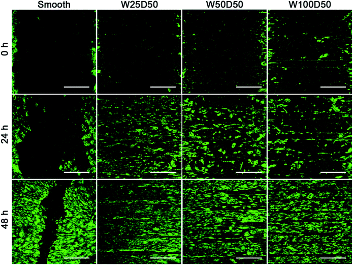 | ||
| Fig. 7 The fluorescent images of in vitro corneal epithelial wound gap on collagen films at 0, 24, 48 h. (scale bar = 400 μm). | ||
Cell differentiation
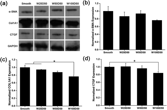
It has been repeated shown that topography is a powerful tool to control cell differentiation, including osteogenic differentiation,55 cardiac differentiation,56 and neuronal differentiation,57 indicating the possibility of regulating keratocyte differentiation with surface topography. Stromal wound healing process has been shown to depend on a complex cascade of many factors.51,58 In some abnormal healing process, a stromal fibrosis, also named corneal haze, forms and leads to vision impairment. According to previous reports, the light scattering structure actually is composed of myofibroblasts and disorganized extracellular matrix produced by them.13,59,60 In normal corneal stromal tissue, keratocytes are relatively quiescent, and aligned collagen fibrils are arranged packed in stacked collagen lamellae to form a highly-organized structure which has lower light scattering.61–63 After stroma injured, keratocytes would transform into more activated fibroblasts and further differentiate into myofibroblasts at the presence of transforming growth factor β (TCF-β), which finally results in the formation of stromal haze. Myofibroblasts are characterized by their unique expression level of alpha smooth muscle actin (αSMA). Connective tissue growth factor (CTGF) is a peptide that stimulates collagen (COLA1A) and αSMA synthesis of myofibroblast and proliferation of fibroblasts.64–66To evaluate the influence of underlying microgrooves on the keratocyte–myofibroblast transformation, mRNA expression level of CTGF, COL1A1, and αSMA in keratocytes on microgrooved collagen films were determined by RT-PCR. Results was shown on Fig. 8. Compared to planar collagen films, patterned collagen films induced significantly downregulated expression level of CTGF, αSMA, and COL1A1 genes. Besides, the attenuation to the expression of the three genes became more profound corresponding to the increase of groove width. Fig. 9 was result of western blotting analysis. It was shown that keratocytes on patterned collagen films tended to express less CTGF, αSMA, and COL1A1, although the difference was not as significant as the difference of gene expression level. The lower αSMA expression indicated that the differentiation of keratocytes into myofibroblasts were inhibited, which may mainly account for the decreased gene expression of CTGF and COL1A1. However, another explanation could be that activities of myofibroblasts was hampered by the surface topography. A study of Myrna et al. showed that nanoscale grooves help to stabilize the fibroblast phenotype compared to flat control,67 and our study performed on microscale grooves showed the same trend. These results suggested that keratocytes transformation are susceptible to topographic feature, and the topographic cues on native corneal stroma may also be involved in the maintenance of quiescent keratocytes. Therefore, the topography feature can be used to prevent the formation of corneal fibrosis.
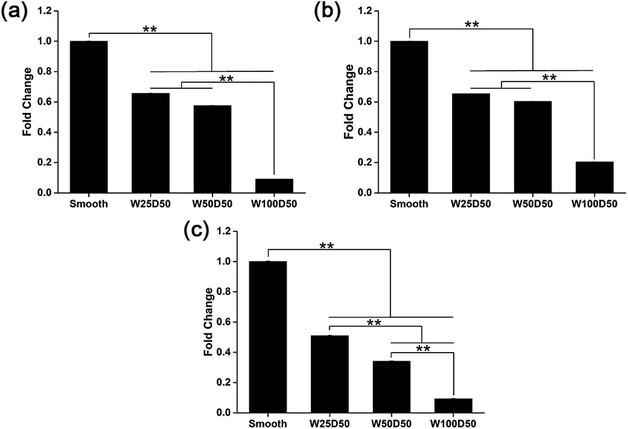 | ||
| Fig. 8 mRNA expression level of (a) CTGF, (b) COL1A1, and (c) αSMA in keratocytes on collagen films. (*p < 0.05, **p < 0.01). | ||
Conclusions
In this paper, the microgrooved collagen films with different features were fabricated as a corneal tissue engineering scaffold to determine the effect of topography on physiochemical properties of collagen films and corneal cell behaviors. It was found that micropatterned collagen films possessed the good swelling performance, optical performance and biodegradability comparable with human cornea and can meet the needs of corneal repair. Besides, in vitro cell experiment demonstrated that topographic cues on collagen films can regulate the fundamental cell behaviors of CECs and keratocytes, including orientation, proliferation, migration and gene expression. CECs and keratocytes on patterned films showed significantly cell alignment and the alignment index is more than 55%. The acceleration of epithelial wound healing and inhibited keratocyte–myofibroblast transformation on patterned collagen films indicates the great potential of surface topography on corneal regeneration and reconstruction.Conflicts of interest
There are no conflicts to declare.Acknowledgements
This work was supported by the National Key Research and Development Program of China (grant number 2017YFC1105004), the National Natural Science Foundation of China (grant numbers 51603074, 31971261), the Natural Science Foundation of Guangdong Province (grant number 2017A030313294), the Guangdong Scientific and Technological Project (grant numbers 2014B090907004, 2015B08020123) and Medical Scientific Research Foundation of Guangdong Province (grant number A2018169).References
- M. J. Burton, Community Eye Health, 2009, 22, 33 Search PubMed.
- I. L. Tsai, C. C. Hsu, K. H. Hung, C. W. Chang and Y. H. Cheng, J. Chin. Med. Assoc., 2015, 78, 212–217 CrossRef PubMed.
- P. Garg, P. V. Krishna, A. Stratis and U. Gopinathan, Eye, 2005, 19, 1106–1114 CrossRef CAS PubMed.
- C. E. Ghezzi, J. Rnjak-Kovacina and D. L. Kaplan, Tissue Eng. B Rev., 2015, 21, 278–287 CrossRef PubMed.
- A. Shah, J. Brugnano, S. Sun, A. Vase and E. Orwin, Pediatr. Res., 2008, 63, 535–544 CrossRef PubMed.
- Y. H. Huang, F. W. Tseng, W. H. Chang, I. C. Peng, D. J. Hsieh, S. W. Wu and M. L. Yeh, Acta Biomater., 2017, 58, 238–243 CrossRef CAS PubMed.
- X. Che, H. Wu, C. K. Jia, H. M. Sun, S. K. Ou, J. Q. Wang, M. V. Jeyalatha, X. He, J. W. Yu, C. Y. Zuo, Z. G. Liu and W. Li, Invest. Ophthalmol. Visual Sci., 2019, 60, 517–527 CrossRef CAS PubMed.
- J. E. Song, B. R. Sim, Y. S. Jeon, H. S. Kim, E. Y. Shin, C. Carlomagno and G. Khang, J. Biomater. Sci. Polym. Ed., 2019, 30, 263–275 CrossRef CAS PubMed.
- H. Kim, J. Jang, J. Park, K. P. Lee, S. Lee, D. M. Lee, K. H. Kim, H. K. Kim and D. W. Cho, Biofabrication, 2019, 11, 9 CrossRef PubMed.
- R. N. Palchesko, S. D. Carrasquilla and A. W. Feinberg, Adv. Healthc. Mater., 2018, 7, 18 Search PubMed.
- Z. Chen, J. J. You, X. Liu, S. Cooper, C. Hodge, G. Sutton, J. M. Crook and G. G. Wallace, Biomed. Mater., 2018, 13, 27 Search PubMed.
- X. Duan and H. Sheardown, Biomaterials, 2006, 27, 4608–4617 CrossRef CAS PubMed.
- A. A. M. Torricelli, A. Santhanam, J. H. Wu, V. Singh and S. E. Wilson, Exp. Eye Res., 2016, 142, 110–118 CrossRef CAS PubMed.
- C. J. Dong and Y. G. Lv, Polymers, 2016, 8, 20 CrossRef PubMed.
- G. A. Abrams, E. Bentley, P. F. Nealey and C. J. Murphy, Cells Tissues Organs, 2002, 170, 251–257 CrossRef CAS PubMed.
- G. A. Abrams, S. S. Schaus, S. L. Goodman, P. F. Nealey and C. J. Murphy, Cornea, 2000, 19, 57–64 CrossRef CAS PubMed.
- G. A. Abrams, S. L. Goodman, P. F. Nealey, M. Franco and C. J. Murphy, Cell Tissue Res., 2000, 299, 39–46 CrossRef CAS PubMed.
- K. M. Meek and C. Boote, Exp. Eye Res., 2004, 78, 503–512 CrossRef CAS PubMed.
- J. Huang, T. Tu, W. B. Wang, Z. Gao, G. D. Zhou, W. J. Zhang, X. L. Wu and W. Liu, J. Biomed. Mater. Res., Part A, 2019, 107, 1366–1378 CrossRef CAS PubMed.
- D. Ho, J. L. Zou, X. J. Chen, A. Munshi, N. M. Smith, V. Agarwal, S. I. Hodgetts, G. W. Plant, A. J. Bakker, A. R. Harvey, I. Luzinov and K. S. Iyer, ACS Nano, 2015, 9, 1767–1774 CrossRef CAS PubMed.
- C. H. Seo, K. Furukawa, K. Montagne, H. Jeong and T. Ushida, Biomaterials, 2011, 32, 9568–9575 CrossRef CAS PubMed.
- S. Nasrollahi, S. Banerjee, B. Qayum, P. Banerjee and A. Pathak, ACS Biomater. Sci. Eng., 2017, 3, 2980–2986 CrossRef CAS.
- S. Di Cio and J. E. Gautrot, Acta Biomater., 2016, 30, 26–48 CrossRef CAS PubMed.
- D. H. Kim, K. Han, K. Gupta, K. W. Kwon, K. Y. Suh and A. Levchenko, Biomaterials, 2009, 30, 5433–5444 CrossRef CAS PubMed.
- C. S. Chen, M. Mrksich, S. Huang, G. M. Whitesides and D. E. Ingber, Science, 1997, 276, 1425–1428 CrossRef CAS PubMed.
- X. K. Shen, P. P. Ma, Y. Hu, G. Q. Xu, J. Zhou and K. Y. Cai, Colloids Surf., B, 2015, 127, 221–232 CrossRef CAS PubMed.
- H. C. Gao, X. D. Cao, H. Dong, X. L. Fu and Y. J. Wang, J. Mater. Sci. Technol., 2016, 32, 901–908 CrossRef.
- M. J. Dalby, N. Gadegaard, R. Tare, A. Andar, M. O. Riehle, P. Herzyk, C. D. W. Wilkinson and R. O. C. Oreffo, Nat. Mater., 2007, 6, 997–1003 CrossRef CAS PubMed.
- B. B. Li, V. Agarwal, D. Ho, J. P. Vede and K. S. Iyer, New J. Chem., 2018, 42, 7237–7240 RSC.
- A. I. Teixeira, G. A. McKie, J. D. Foley, P. J. Berticsc, P. F. Nealey and C. J. Murphy, Biomaterials, 2006, 27, 3945–3954 CrossRef CAS PubMed.
- A. I. Teixeira, G. A. Abrams, P. J. Bertics, C. J. Murphy and P. F. Nealey, J. Cell Sci., 2003, 116, 1881–1892 CrossRef CAS PubMed.
- S. A. Pot, S. J. Liliensiek, K. E. Myrna, E. Bentley, J. V. Jester, P. F. Nealey and C. J. Murphy, Invest. Ophthalmol. Visual Sci., 2010, 51, 1373–1381 CrossRef PubMed.
- S. Koo, S. J. Ahn, H. Zhang, J. C. Wang and E. K. F. Yim, Cell. Mol. Bioeng., 2011, 4, 399–410 CrossRef CAS.
- M. D. M. Evans, G. A. McFarland, S. Taylor and X. F. Walboomers, Biomaterials, 2005, 26, 1703–1711 CrossRef CAS PubMed.
- B. Yanez-Soto, S. J. Liliensiek, J. Z. Gasiorowski, C. J. Murphy and P. F. Nealey, Biomaterials, 2013, 34, 9244–9251 CrossRef CAS PubMed.
- W. Zhang, J. L. Chen, L. J. Backman, A. D. Malm and P. Danielson, Adv. Healthc. Mater., 2017, 6, 11 CrossRef.
- Q. Zhang, H. Dong, Y. L. Li, Y. Zhu, L. Zeng, H. C. Gao, B. Yuan, X. F. Chen and C. B. Mao, ACS Appl. Mater. Interfaces, 2015, 7, 23336–23345 CrossRef CAS PubMed.
- H. C. Gao, H. Dong, X. D. Cao, X. L. Fu, Y. Zhu, C. B. Mao and Y. J. Wang, Langmuir, 2015, 31, 6797–6806 CrossRef CAS PubMed.
- S. P. Srinivas, Optom. Vis. Sci., 2010, 87, E239–E254 Search PubMed.
- J. E. Harris and L. T. Nordquist, Am. J. Ophthalmol., 1955, 40, 100–110 CrossRef CAS PubMed.
- E. J. Tocce, V. K. Smirnov, D. S. Kibalov, S. J. Liliensiek, C. J. Murphy and P. F. Nealey, Biomaterials, 2010, 31, 4064–4072 CrossRef CAS PubMed.
- A. I. Teixeira, P. F. Nealey and C. J. Murphy, J. Biomed. Mater. Res., Part A, 2004, 71, 369–376 CrossRef PubMed.
- S. J. Liliensiek, S. Campbell, P. F. Nealey and C. J. Murphy, J. Biomed. Mater. Res., Part A, 2006, 79, 185–192 CrossRef CAS PubMed.
- J. Meyle, K. Gultig and W. Nisch, J. Biomed. Mater. Res., 1995, 29, 81–88 CrossRef CAS PubMed.
- S. A. Fraser, Y. H. Ting, K. S. Mallon, A. E. Wendt, C. J. Murphy and P. F. Nealey, J. Biomed. Mater. Res., Part A, 2008, 86, 725–735 CrossRef PubMed.
- C. J. Bettinger, Z. T. Zhang, S. Gerecht, J. T. Borenstein and R. Langer, Adv. Mater., 2008, 20, 99–103 CrossRef CAS PubMed.
- J. Lu, M. P. Rao, N. C. MacDonald, D. Khang and T. J. Webster, Acta Biomater., 2008, 4, 192–201 CrossRef CAS PubMed.
- X. Yao, R. Peng and J. Ding, Adv. Mater., 2013, 25, 5257–5286 CrossRef CAS PubMed.
- Q. Zhang, Y. L. Li, H. Sun, L. Zeng, X. Li, B. Yuan, C. Y. Ning, H. Dong and X. F. Chen, RSC Adv., 2015, 5, 47975–47982 RSC.
- L. Lu, P. S. Reinach and W. W. Y. Kao, Exp. Biol. Med., 2001, 226, 653–664 CrossRef CAS PubMed.
- A. V. Ljubimov and M. Saghizadeh, Prog. Retin. Eye Res., 2015, 49, 17–45 CrossRef CAS PubMed.
- S. A. Biela, Y. Su, J. P. Spatz and R. Kemkemer, Acta Biomater., 2009, 5, 2460–2466 CrossRef CAS PubMed.
- J. P. Kaiser, A. Reinmann and A. Bruinink, Biomaterials, 2006, 27, 5230–5241 CrossRef CAS PubMed.
- S. Li, S. Bhatia, Y. L. Hu, Y. T. Shin, Y. S. Li, S. Usami and S. Chien, Biorheology, 2001, 38, 101–108 CAS.
- D. Karazisis, S. Petronis, H. Agheli, L. Emanuelsson, B. Norlindh, A. Johansson, L. Rasmusson, P. Thomsen and O. Omar, Acta Biomater., 2017, 53, 559–571 CrossRef CAS PubMed.
- L. D. Ghosh, A. Jain, N. R. Sundaresan and K. Chatterjee, Mater. Sci. Eng., C, 2018, 88, 104–114 CrossRef PubMed.
- L. Q. Song, K. Wang, Y. Li and Y. Yang, Colloids Surf., B, 2016, 148, 49–58 CrossRef CAS PubMed.
- S. Saika, O. Yamanaka, Y. Okada and T. Sumioka, Exp. Eye Res., 2016, 142, 40–48 CrossRef CAS PubMed.
- T. Moller-Pedersen, Exp. Eye Res., 2004, 78, 553–560 CrossRef CAS PubMed.
- J. V. Jester, W. M. Petroll and H. D. Cavanagh, Prog. Retin. Eye Res., 1999, 18, 311–356 CrossRef CAS PubMed.
- J. R. Hassell and D. E. Birk, Exp. Eye Res., 2010, 91, 326–335 CrossRef CAS PubMed.
- L. J. Muller, E. Pels, L. Schurmans and G. Vrensen, Exp. Eye Res., 2004, 78, 493–501 CrossRef CAS PubMed.
- D. M. Maurice, J. Physiol., 1957, 136, 263–286 CrossRef CAS PubMed.
- A. Igarashi, H. Okochi, D. M. Bradham and G. R. Grotendorst, Mol. Biol. Cell, 1993, 4, 637–645 CrossRef CAS PubMed.
- K. Kikuchi, T. Kadono, H. Ihn, S. Sato, A. Igarashi, H. Nakagawa, K. Tamaki and K. Takehara, J. Invest. Dermatol., 1995, 105, 128–132 CrossRef CAS PubMed.
- G. R. Grotendorst and M. R. Duncan, FASEB J., 2005, 19, 729–738 CrossRef CAS PubMed.
- K. E. Myrna, R. Mendonsa, P. Russell, S. A. Pot, S. J. Liliensiek, J. V. Jester, P. F. Nealey, D. Brown and C. J. Murphy, Invest. Ophthalmol. Visual Sci., 2012, 53, 811 CrossRef CAS PubMed.
| This journal is © The Royal Society of Chemistry 2019 |

