 Open Access Article
Improving the size uniformity of dendritic fibrous nano-silica by a facile one-pot rotating hydrothermal approach†
Yabin Wang‡
 *,
Keke Hu‡,
Juan He and
Yantu Zhang
Shaanxi Key Laboratory of Chemical Reaction Engineering, College of Chemistry and Chemical Engineering, Yan'an University, Yan'an 716000, Shaanxi, P. R. China. E-mail: ybw_bingerbingo@126.com
First published on 9th August 2019
Abstract
Dendritic fibrous nano-silica (DFNS), also well-known as KCC-1, possesses three-dimensional center-radial nanochannels and hierarchical nanopores. Compared with conventional mesoporous materials like SBA-15, these special structural characteristics endow DFNS with more accessible internal space, higher specific surface area, larger pore volume, etc. Even though great progress has been achieved, the as-prepared KCC-1 nanospheres exhibit extremely non-uniform diameters and their sizes differ enormously in almost all available traditional synthesis approaches. Herein, a facile and low-cost one-pot rotating hydrothermal approach is adopted to improve the size uniformity of dendritic fibrous nano-silica. Stirring rates of 30, 60, 90, 120, and 150 (the maximum) revolutions per minute (rpm) can influence KCC-1 uniformity to certain extents. Among them, 60 rpm can be considered to be an ideal stirring rate for relatively uniform KCC-1 because of the best sufficient contact of reaction phases. A plausible synthesis mechanism can be explained in terms of continuously variable stress conditions of the reaction mother liquor (i.e., the bicontinuous microemulsion) during the fabrication process. To be specific, except for gravity (G), this technique brings about the centrifugal force (F) stemming from the stirring rate, and the buoyancy (f) originated from vigorous reversal of organic phase in the reaction solution. These forces synergistically mix organic phase and water phase, which generates new bicontinuous microemulsion droplets (BMDs) to supplement the consumed ones. All in all, this approach as well as the synthesis equipment is simple, inexpensive, and reproducible for large-scale KCC-1 preparation with improved size uniformity.
Introduction
Dendritic fibrous nano-silica (DFNS),1–6 also originally denoted and well-known as KCC-1,7–19 possesses unique structural characteristics of three-dimensional (3D) center-radial nanochannels and hierarchical nanopores which give rise to highly accessible internal spaces, open pore channels, large pore volumes, etc. Diverse guest species, such as functional molecules or nano-particles (NPs), could be easily transported through the radial porous architectures to achieve their efficient loading or react with the chemically active sites on these nanochannels.20–28 During the last nine years, KCC-1 has attracted considerable attention and experienced rapid development in terms of synthesis techniques, formation mechanisms, functionalization approaches, and application fields.5,29Even though great progress has been achieved, there still exist many issues surrounding the synthesis and application of KCC-1. One of them is that the as-prepared nanospheres are extremely non-uniform and their sizes differ enormously in almost all available conventional synthesis processes.2,7,10,12 It is clear that a microwave-assisted hydrothermal system was adopted from the milestone work of Polshettiwar et al. who pioneeringly synthesized and defined KCC-1.7 Following the same fabrication process7 in our microwave-assisted hydrothermal instrument (Fig. S1†), KCC-1 was successfully prepared and characterized with SEM plus TEM techniques (Fig. S2†). Dendritic and fibrous textures are easily identified for most products, while the as-prepared nanospheres display non-uniform diameters with large differences (Fig. S2a†). Polshettiwar's team2 and a few groups30,31 recently began to fabricate KCC-1 with round-bottom flask systems; some other research teams utilized Teflon-sealed hydrothermal reactor systems.32,34 These approaches based on different reaction instruments were able to prepare KCC-1 effectively, whereas evident non-uniformity issue of nanosphere sizes has not been resolved yet. Fortunately, non-uniform size with large differences does not influence KCC-1 applications like catalysis,32,33 cancer and tumour therapy,35,36 gene and protein delivery,37 water treatment,38,39 chromatography,40,41 dye-sensitized solar cell and supercapacitor,42,43 etc. For this reason, only limited attentions have been paid and few investigations have been conducted to ameliorate KCC-1 size uniformity. Very recently, Jang et al. tried to improve KCC-1 uniformity by applying a cooling stage prior to the conventional fabrication process,44 which is efficient but multi-stepped. As KCC-1 subject develops, improvement of KCC-1 uniform size with facile techniques would be significant for more sophisticated synthesis science and other application fields, like chemical mechanical planarization (CMP)45 and photonic crystal46 where uniform nanoparticles bring about more superior performances than the non-uniform.
After carefully comparing the aforementioned synthesis methods with different reaction instruments, one parameter drew our attentions, i.e., stirring rate (R). For the microwave-assisted hydrothermal system, R could be considered as naught because the instrument rotated horizontally without blending the organic phase and the water phase of the reaction solution (Fig. S1 and Video S1†). As for round-bottom flask systems, the reaction solutions were commonly gently stirred by Teflon-coated stirring bars without vigorously mixing the reaction phases of the oil (usually upper) and the water (usually lower).30,31 With regard to Teflon-sealed hydrothermal reactors, they were kept still and held for a certain time,32–34 let alone mixing the reaction solution. The precise and sophisticated synthesis mechanism of the above methods will be elucidated in our mechanism analysis section later.
Herein, based on the above consideration, we perform a modified method to ameliorate the size uniformity of KCC-1 by a facile one-pot rotating hydrothermal approach (Fig. S3†) where strengthened stirring is introduced to the synthesis process for sufficient mixture of the reaction mother liquor (Video S2†). To be specific, low-cost Teflon-lined autoclaves filled with KCC-1 mother liquors are fixed at a spindle in the hydrothermal reactor, and then a stirring rate is realized via a power-driven motor by which the organic and water phases could be mixed constantly during the reaction process. The as-prepared KCC-1 nanospheres exhibit improved uniformity to certain extents at various stirring rates of 30, 60, 90, 120, and 150 rpm (the maximum) and could be applied for potential fields.
Experimental
Chemicals, instruments, and synthesis process
Tetraethylorthosilicate (TEOS), cetylpyridinium bromide (CPB), cyclohexane, pentanol, and urea were purchased from Aladdin Industrial Corporation. All of the chemicals were employed as analytical reagent (AR) without further purification. Microwave synthesis was carried out by a XH-800S microwave hydrothermal synthesis system (China), while one-pot rotating hydrothermal synthesis was conducted with a JX-8-200 homogeneous reactor (China). Therein, different stirring rates were applied from the minimum to the maximum, including 0, 30, 60, 90, 120, and 150 rpm (Video S2†), respectively.In a typical synthesis,7 tetraethyl orthosilicate (TEOS, 0.012 mol) was dissolved in a mixed solution of pentanol (1.5 mL) and cyclohexane (30 mL). Subsequently, another solution of cetylpyridinium bromide (CPB, 0.0026 mol) and urea (0.01 mol) in water (30 mL) was added to the above solution. The as-prepared mixture solution was stirred for 30 min at room temperature and placed in a Teflon-sealed autoclave. Then, the autoclave was fixed in the homogeneous reactor and rotated with different stirring rate at 120 °C for 4 h. Finally, the product isolated by centrifugation was washed with distilled water and acetone for three times, respectively. The as-synthesized powder was calcined at 550 °C for 6 h in air.
Characterization
Scanning electron microscopy (SEM) was conducted with a HITACHI-SU8010 field emission scanning electron microscope (Japan). Transmission electron microscopy (TEM) and scanning transmission electron microscopy (STEM) were carried out by a JEM-F200 transmission electron microscope (Japan). X-ray diffraction (XRD) patterns were collected on a PANalytical X'Pert PRO X-ray diffractometer using Cu Kα radiation (Netherlands). N2 adsorption–desorption isotherms were measured with an Autosorb-iQ2-MP isothermal nitrogen sorption analyzer (USA). The surface area and pore volume were calculated by BET analysis. The pore size distribution was obtained from the adsorption branches of the isotherms by means of the BJH method. Fourier transform infrared spectroscopy (FTIR) was collected on a NEXUS-870 infrared spectrometer (USA).Results and discussion
SEM and diameter distribution curve analysis
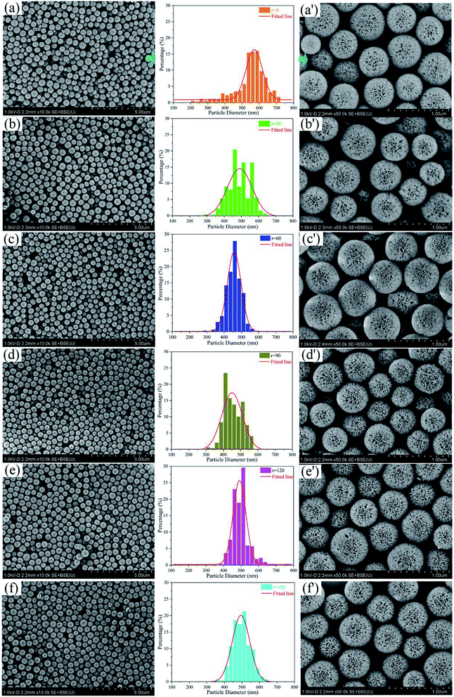
Fig. 1 exhibits SEM images and diameter distribution curves of KCC-1 prepared by one-pot rotating hydrothermal technique without and with different stirring rates. For each group, the curve is extracted from SEM image with a large scale of 5 μm (Fig. 1a–f) where over 350 nanospheres are counted and analyzed. Diameter distribution is plotted with percentage as a function of particle diameter. SEM image of 1 μm scale (Fig. 1a′–f′) is randomly selected to verify the uniformity. The distribution range and the shape of the fitted line change as the stirring rate increases from 0 to 150 rpm. Table S1† summarizes the range value of diameter distribution (as well as the interval difference Δ), the symmetry of distribution percentage referred to the fitted line, KCC-1 uniformity, the top three percentages in diameter distribution range, and peculiar morphology evaluation (broken or immature) for each sample.The results can be concluded as follows: (1) KCC-1 prepared by the one-pot rotating hydrothermal technique without and with different stirring rates show improved size uniformity, compared to KCC-1 fabricated by the microwave-assisted hydrothermal system (Fig. S2a†). (2) Nanospheres prepared without stirring (r = 0) have the most uneven sizes with diameter size ranging from 200 to 725 nm (Δ = 525), which leads to an extremely asymmetric distribution percentage. When the reaction mother liquor is stirred, the range of KCC-1 diameter distribution sharply becomes narrow (Δ ≤ 400), indicating that stirring can make nanospheres relatively uniform. Especially, when the rate equals to 60 rpm, the symmetry of its distribution percentage is excellent, resulting in the best uniformity as testified by Fig. 1c′. (3) The top three percentages in each diameter distribution are different both in range and percentage value, and even discontinuously appear as the rate is 30 or 90 rpm. The maximum percentage for each group varies, implying that different stirring rate can prepare KCC-1 nanosphere with diverse sizes. (4) Some broken and immature nanoparticles emerge when the reaction solution is not stirred (r = 0) or stirred with the maximum rate (r = 150) as demonstrated in Fig. S4a and b.† When stirring rate increases from 30 to 120 rpm, none of broken nanoparticles is observed and immature ones begin to increase (Fig. S4c–f†). As displayed in Video S2,† moderate stirring can sufficiently mix KCC-1 mother solution (r = 30 to 120). However, the maximum stirring rate (r = 150) cannot achieve continuous mixture, which generates more broken and immature nanoparticles (Video S2†). In view of the above analysis, 60 rpm from the one-pot rotating hydrothermal system can be considered to be an ideal stirring rate. Other stirring rates can influence the uniformity of the as-prepared nanospheres to some extents.
TEM and STEM analysis
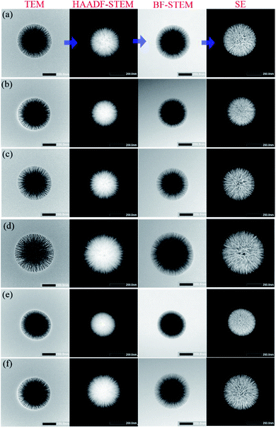
TEM, high-angle annular dark field (HAADF-STEM), bright field (BF-STEM), and secondary electron (SE) images of single KCC-1 prepared by the one-pot rotating hydrothermal technique without or with different stirring rates are exhibited in Fig. 2 to thoroughly reveal the textures of the as-prepared nanospheres. TEM images certify that each individual has dendrimer-like architecture with center-radial fibrous nanochannels distributed in all directions. HAADF-STEM and BF-STEM results suggest that all KCC-1 samples are solid with well-defined and ordered nanofibers coming out from the centers. SE results demonstrate that these nanofibers are sheet-like and compose nanowrinkles appeared on the surfaces of the as-obtained nanospheres. Therefore, it is conceivable that nanopores develop by the squeezes of these nanowrinkles. In conclusion, radial fibrous SiO2 nanowrinkles bring about the formation of center-radial nanopores with gradually increased pore sizes from particle interior to surface. It should be mentioned here that the final imagings of KCC-1 are different on basis of TEM, HAADF-STEM, BF-STEM, or SE mode, which prompts researchers to put forward various structural models. On the whole, morphological models from TEM and BF-STEM are nearly identical, but greatly different from that of HAADF-STEM, or SE mode.Some typically simulated three dimensional (3D) structural models of KCC-1 nanosphere are illustrated in Fig. S5a–e† from teams of Vivek Polshettiwar,5,14 Dongyuan Zhao,47,48 Xin Du,49,50 Chengzhong Yu,51,52 and Jin Soo Kang,42 respectively. The first model (Fig. S5a†) is extracted by HAADF-STEM imaging and resembles a sea urchin that has its core covered with center-radial spikes. Other model obtained by means of SEM or/and TEM render their regular (Fig. S5b–d†) or irregular (Fig. S5e†) nanochannels inserted in the sphere bulks. These models greatly differ from the first model and are distinguishing with each other to a certain extent. The reason for this disunity is that each team possesses individual insight into KCC-1 morphologies or architectures on account of their researches where various experimental conditions lead to discriminating topographies, as verified by the corresponding SEM, TEM, and/or STEM results. Furthermore, Yu's team recently has synthesized actual sea urchin-like silica nanoparticles and denominated them as rambutan-like morphologies with spike-type subunit (Fig. S5f†).52 The model of rambutan-like silica nanoparticles is nearly identical with the one in Fig. S5a.† Thus, these models might cause confusion if the references are not clearly clarified, i.e., based on HAADF-STEM, SEM, or TEM imagings. STEM-EDS mapping of KCC-1 prepared at 60 rpm in Fig. 3 shows that silicon (Si) and oxygen (O) elements constituted KCC-1 nanospheres are homogeneously disperse in their skeletons.
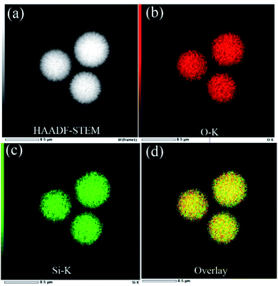 | ||
| Fig. 3 STEM-EDS mapping of KCC-1 prepared at 60 rpm. FT-IR, XRD, N2 adsorption–desorption isotherms analyses. | ||
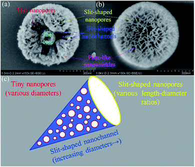
FT-IR spectrograms of the as-prepared KCC-1 are displayed in Fig. 4a. All samples possess the same peak patterns and positions, implying that identical chemical functional groups exist on these nanospheres. To be specific, 810 cm−1, 963 cm−1, 1090 cm−1 and 1645 cm−1 attribute to symmetrical stretching vibration of Si–O,53 vibration absorptions of Si–OH,54 Si–O–Si, and H2O,55 respectively. The typical absorption of –OH group at 3430 cm−1 comes from the adsorbed H2O or/and Si–OH groups on KCC-1 surfaces. Fig. 4b shows XRD patterns of the KCC-1 prepared by the one-pot rotating hydrothermal technique with different stirring rates. The same broad peaks centered at 22° between 15° and 30° correspond to amorphous silica.15,54,55 The N2 adsorption–desorption isotherms of the as-prepared KCC-1 and their corresponding pore size distributions are shown in Fig. 4c and d, respectively. In the isotherms, all the samples own similar IV characters with typical H3 hysteresis loops (Fig. S6†). Actually, there exists controversy about the type of hysteresis loop for KCC-1. Yang et al.56 and Liu's team57 considered that KCC-1 had a H1 hysteresis loop, while Suendo et al. regarded it as a H1 or H3 hysteresis loop.17,34 According to IUPAC regulation,58 type H1 is often associated with porous materials known to consist of agglomerates (an assemblage of particles rigidly joined together) and hence has narrow distributions of pore size. Type H3 loop is observed with aggregates (an assemblage of particles loosely coherent) of plate-like particles giving rise to slit-shaped pores. Fortunately, an immature KCC-1 nanosphere is captured and its internal texture is directly observed (Fig. 5a). Plate-like nanowrinkles constitute slit-shaped nanochannels and nanopores (Fig. 5a and b). In addition, pore size is widely distributed for all KCC-1 as demonstrated in Fig. 4d. These results reveal that KCC-1 nanospheres own the typical H3 hysteresis loop. The corresponding BET surface area (SBET) and pore volume (VP), as well as the main pore distribution for each sample are tabulated in Table S2.† The SBET (as well as VP) values of each sample are 202.562 (0.497), 402.676 (1.163), 421.374 (1.314), 387.642 (1.274), 389.467 (1.078), and 413.774 (1.221), respectively. It is apparent that KCC-1 nanospheres fabricated without stirring obtain the minimum SBET and VP, owing to the existence of broken and immature KCC-1 as well as non-uniform ones. When the stirring rate boosts, SBET and VP for each sample greatly increase, nearly twice than that of KCC-1 fabricated without stirring. Among these stirring specimens, KCC-1 obtained at 60 rpm owns the biggest SBET and VP; this finding clearly indicates that better uniformity brings about the finer textural characters and parameters. The pore sizes of KCC-1 samples exhibit wide distributions with two evident ones centered at 2–5 and 11–15 nm as displayed in Fig. 4d, which could be attributed to various nanopores in KCC-1. The sample prepared without stirring shows weaker peaks and distributions than the stirring samples, also probably due to the influence of broken/immature KCC-1 and non-uniform ones.
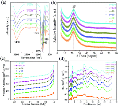 | ||
| Fig. 4 FT-IR (a), XRD (b), N2 adsorption–desorption isotherms (c), and their corresponding pore size distributions (d) of KCC-1 synthesized by a facile one-pot rotating hydrothermal approach with different stirring rates of 0, 30, 60, 90, 120, and 150 rpm, respectively. Note: each curve of a higher stirring rate shifts 200 cm3 STP g−1 and 0.4 cm3 g−1 nm−1 upward in Fig. 3c and d, respectively. | ||
Combined with the architecture of the immature KCC-1 in Fig. 5a, nanopores can be simply divided into three types. The first one is the tiny nanopores stemmed from the adjacent plate-like structures in KCC-1 wrinkled skeletons. The second one is the slit-shaped nanochannel introduced by the aggregate of abundant plate-like structures between the nanowrinkles. The pore size of individual nanochannel gradually increases from the internal centers of KCC-1 (the core, Fig. 5a) to the external surfaces along the nanowrinkles. The third type is the nanopores exerted by the squeezes of the nanowrinkles and existed on KCC-1 surface. One of the finest ways to describe the structural morphologies is the metaphor of cone-like or conical pores.59,60 The diameters of the outermost nanopores range from several nm to tens (Fig. S7†). On the basis of the above results, it can be considered that the cone-like cavities and the nanopores in cavity walls collectively constitute the hierarchical structures of KCC-1 nanospheres (Fig. 5c), which results in wide distribution of KCC-1 pore size.
As is seen in Fig. S3 and Video S2,† ten autoclaves of 100 mL can be simultaneously utilized to synthesize KCC-1. Therefore, ten parallel tests were performed to verify the repeatability and calculate KCC-1 yield. Four specimens are randomly selected and their products present satisfactory sizes (Fig. S8†), proving excellent reproducibility of this method to ameliorate the uniformity. In practice, 5.76 g KCC-1 were finally obtained once. If Si from TEOS theoretically turns into SiO2 (7.21 g), the yield of KCC-1 prepared at 60 rpm is about 80% (an average value of the ten parallel tests). Hence, this technique can guide or act as a reference for large-scale KCC-1 preparation with improved uniformity.
The preparation mechanism
For the sake of better understanding, KCC-1 reaction mother liquor was simply described as a mixed solution of organic phase and water phase in previous sections (Fig. S1 and S3†). Actually, KCC-1 with well-defined textures can be synthesized on the condition that the reaction mother liquor must be a bicontinuous microemulsion (Winsor III), as verified by Lee's team.61,62 For typical ternary system composed of surfactant (CPB in this research), organic phase (TEOS, cyclohexane, and pentanol here), and water phase, it could be classified into four types according to the numbers and types of phases in the equilibrium state. They are two multiphase system containing a microemulsion layer (Winsor I and Winsor II), three multiphase system containing a microemulsion layer (Winsor III), and one single-phase microemulsion system (Winsor IV).63 Among them (Fig. 6a), Winsor I system includes an extra oil layer on the top of the mixture solution and an oil-in-water microemulsion layer at the bottom. Winsor II system is a biphasic system with a water-in-oil microemulsion layer atop and an extra water layer at the bottom. Winsor III system possesses a bicontinuous microemulsion phase in the middle layer of the mixture where most of the surfactant, water, and oil are included. The degree of freedom defined by Gibbs' phase rule determines the structures of the multiphase emulsion systems, and further influences the constructions of the as-prepared products.61 Winsor I and II phases are mono-variant two-phase systems with two degrees of freedom; Winsor III is a three-phase system with zero degrees of freedom; Winsor IV as mono-phasic microemulsion area have two degrees of freedom. For Winsor III system, even though the relative concentration of the total components changes, the composition ratio in the microemulsion layer is invariant, resulting in constant substructures of the spherical KCC-1. On the contrary, Winsor I, Winsor II and Winsor IV cannot produce KCC-1 nanospheres. Polshettiwar et al. recently also proved that the structural evolution of bicontinuous microemulsion droplets (BMDs) and their subsequent coalescence were responsible for the formation of complex KCC-1 morphology.6 Up to now, it is clear that KCC-1 can be prepared by Winsor III system with a bicontinuous microemulsion where the composition ratio is constant.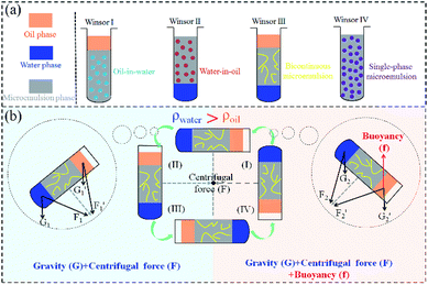 | ||
| Fig. 6 Schematic illustrations of microemulsion systems, namely, Winsor I to Winsor IV (a), and stress conditions of Winsor III system in a circle (b). | ||
Referring to Cartesian coordinate system (the first quadrant to the fourth), when a certain stirring rate is added to KCC-1 mother liquor, the autoclave moves circularly in the four quadrants (Fig. 6b). Because the density of water phase outweighs that of cyclohexane oil phase (ρwater > ρoil), therefore, water phase locates at the bottom of the bicontinuous microemulsion and oil phase is on the top in quadrant II and III. When the autoclave successively enters in quadrant IV and I, KCC-1 mother liquor reverses with oil at the bottom and water on the top. As a result, the stress condition of Winsor III system alters in the four quadrants and can be simply divide into two cases as illustrated in Fig. 6b. In quadrant II and III, KCC-1 mother liquor subjects to the force of gravity (G) and the centrifugal force (F). In quadrant IV and I, cyclohexane oil phase receives an additional buoyancy (f) except for G and F. As is well-known that centrifugal force F is determined by rate (F = mv2/r), hence, different stress conditions originated from various stirring rates influence the KCC-1 mother liquor during the reaction. On basis of the above fact, plausible preparation mechanism can be interpreted as follows. With vigorous and moderate stirring (Fig. 1b–f), organic phase and water phase can thoroughly mixed as new BMDs that enter the bicontinuous microemulsion layer to supply adequate reactants, giving rise to KCC-1 nanospheres with relatively uniform diameters as the chemical reactions proceed. Without stirring (Fig. 1a) or insufficient stirring (Fig. S2†), new BMDs cannot be timely generated to supplement bicontinuous microemulsion layer, leading to KCC-1 nanospheres with various diameters as well as broken and immature nanoparticles. Compared to microwave-assisted hydrothermal system (horizontally rotating) and round-bottom flask system (stirring with Teflon-coated stirring bars), the one-pot rotating hydrothermal system mixes the reaction mother liquor by reversing the autoclaves to an extreme, resulting in KCC-1 with relatively uniform diameters.
Conclusions
In summary, KCC-1 with improved size uniformity can be realized by a facile one-pot rotating hydrothermal approach. When a stirring rate of 60 rpm is utilized, KCC-1 with diameters centered at ca. 400–500 nm can be easily prepared with an 80% yield. Other stirring rates, including 0, 30, 90, 120, and 150 rpm, could influence KCC-1 uniformity to a certain extent and also determine the amount of the broken nanoparticles as well as the immature. Plausible synthesis mechanism can be ascribed to continuously variable stress conditions of the bicontinuous microemulsion. Specifically, the gravity (G), the centrifugal force (F), and the buoyancy (f) synergistically mix organic phase and water phase during the fabrication process, which develops new BMDs to supplement the consumed ones, resulting in KCC-1 with relatively uniform diameters. On the whole, this approach is simple, low-cost, and reproducible for large-scale KCC-1 preparation. The as-prepared KCC-1 could be applied for potential fields where uniform nanospheres are urgent, like KCC-1 embedded in hybrid membrane towards CO2 capture (KCC-1 uniformity greatly influences the quality of the membrane).64Conflicts of interest
There are no conflicts to declare.Acknowledgements
This work was supported by National Natural Science Foundation of China (Grant No. U1607105), Natural Science Basic Research Plan in Shaanxi Province of China (2019JQ-104), Doctoral Research Program of Yan'an University (YDBK2017-39), the Research Program of Yan'an University (YDQ2018-14), Shaanxi Province Training Program of Innovation and Entrepreneurship for Undergraduates (201820042), Innovation Project of Graduate Education from Yan'an University (YCX201822).Notes and references
- A. Maity, S. Mujumdar and V. Polshettiwar, ACS Appl. Mater. Interfaces, 2018, 10, 23392–23398 CrossRef CAS PubMed.
- A. Maity and V. Polshettiwar, ACS Appl. Nano Mater., 2018, 1, 3636–3643 CrossRef CAS.
- Y. Wang, Y. Wang, X. Li, J. Li, L. Su, X. Zhang and X. Du, ACS Sustainable Chem. Eng., 2018, 6, 14071–14081 CrossRef CAS.
- W. Byoun, S. Jung, N. M. Tran and H. Yoo, ChemistryOpen, 2018, 7, 349–355 CrossRef CAS PubMed.
- A. Maity and V. Polshettiwar, ChemSusChem, 2017, 10, 3866–3913 CrossRef CAS PubMed.
- A. Maity, A. Das, D. Sen, S. Mazumder and V. Polshettiwar, Langmuir, 2017, 33, 13774–13782 CrossRef CAS PubMed.
- V. Polshettiwar, D. Cha, X. Zhang and M. B. Jean, Angew. Chem., Int. Ed., 2010, 49, 9652–9656 CrossRef CAS PubMed.
- V. Polshettiwar, J. Thivolle-Cazat, M. Taoufik, F. Stoffelbach and S. Norsic, Angew. Chem., Int. Ed., 2011, 50, 2747–2751 CrossRef CAS PubMed.
- A. Fihri, D. Cha, M. Bouhrara, N. Almana and V. Polshettiwar, ChemSusChem, 2012, 5, 85–89 CrossRef CAS PubMed.
- M. Bouhrara, C. Ranga, A. Fihri, R. R. Shaikh, P. Sarawade, A. H. Emwas, M. N. Hedhili and V. Polshettiwar, ACS Sustainable Chem. Eng., 2013, 1, 1192–1199 CrossRef CAS.
- X. Huang, Z. Tao, J. C. Praskavich, A. Goswami, J. F. Al-Sharab, T. Minko, V. Polshettiwar and T. Asefa, Langmuir, 2014, 30, 10886–10898 CrossRef CAS PubMed.
- A. S. Lilly Thankamony, C. Lion, B. Singh, A. J. Perez Linde, D. Carnevale, G. Bodenhausen, H. Vezin, O. Lafon and V. Polshettiwar, Angew. Chem., Int. Ed., 2015, 54, 2190–2193 CrossRef PubMed.
- Z. S. Qureshi, P. B. Sarawade, M. Albert, V. D'Elia, M. N. Hedhili and K. Köhler, ChemCatChem, 2015, 7, 635–642 CrossRef CAS.
- R. Singh, R. Bapat, L. Qin, H. Feng and V. Polshettiwar, ACS Catal., 2016, 6, 2770–2784 CrossRef CAS.
- Z. S. Qureshi, P. B. Sarawade, I. Hussain, H. Zhu, H. Al-Johani, D. H. Anjum, M. N. Hedhili, N. Maity, V. D'Elia and J. M. Basset, ChemCatChem, 2016, 8, 1671–1678 CrossRef CAS.
- B. Singh and V. Polshettiwar, J. Mater. Chem. A, 2016, 4, 7005–7019 RSC.
- M. Y. S. Hamid, M. L. Firmansyah, S. Triwahyono, A. A. Jalil, R. R. Mukti, E. Febriyanti, V. Suendo, H. D. Setiabudi, M. Mohamed and W. Nabgan, Appl. Catal., A, 2017, 532, 86–94 CrossRef CAS.
- S. Ravi, S. Zhang, Y.-R. Lee, K.-K. Kang, J.-M. Kim, J.-W. Ahn and W.-S. Ahn, J. Ind. Eng. Chem., 2018, 67, 210–218 CrossRef CAS.
- S. M. Saadati and S. M. Sadeghzadeh, Catal. Lett., 2018, 148, 1692–1702 CrossRef CAS.
- R. Singh, R. Belgamwar, M. Dhiman and V. Polshettiwar, J. Mater. Chem. B, 2018, 6, 1600–1604 RSC.
- V. Califano, F. Sannino, A. Costantini, J. Avossa, S. Cimino and A. Aronne, J. Phys. Chem. C, 2018, 122, 8373–8379 CrossRef CAS.
- Y. Wang, J. Zhou, B. Zhang, L. Tian, Z. Ali and Q. Zhang, Chem. Eng. J., 2017, 327, 932–940 CrossRef CAS.
- X. L. Xue, W. Z. Lang, X. Yan and Y. J. Guo, ACS Appl. Mater. Interfaces, 2017, 9, 15408–15423 CrossRef CAS PubMed.
- Z. Chen, C. Zhao, E. Ju, H. Ji, J. Ren, B. P. Binks and X. Qu, Adv. Mater., 2016, 28, 1682–1688 CrossRef CAS PubMed.
- Y. Hong, Y. Yao, H. Zhao, Q. Sheng, M. Ye, C. Yu and M. Lan, Anal. Chem., 2018, 90, 7617–7625 CrossRef CAS PubMed.
- N. A. A. Fatah, S. Triwahyono, A. A. Jalil, N. Salamun, C. R. Mamat and Z. A. Majid, Chem. Eng. J., 2017, 314, 650–659 CrossRef CAS.
- M. Dhiman and V. Polshettiwar, J. Mater. Chem. A, 2016, 4, 12416–12424 RSC.
- Z. Dong, G. Yu and X. Le, New J. Chem., 2015, 39, 8623–8629 RSC.
- X. Du and S. Z. Qiao, Small, 2015, 11, 392 CrossRef CAS PubMed.
- Z. Mohammadbagheri and A. Najafi Chermahini, J. Ind. Eng. Chem., 2018, 62, 401–408 CrossRef CAS.
- Z. Ali, L. Tian, B. Zhang, N. Ali, M. Khan and Q. Zhang, Enzyme Microb. Technol., 2017, 103, 42–52 CrossRef CAS PubMed.
- Z. Dong, X. Le, X. Li, Z. Wei, C. Dong and J. Ma, Appl. Catal., B, 2014, 158, 129–135 CrossRef.
- S. M. Sadeghzadeh, R. Zhiani, M. Khoobi and S. Emrani, Microporous Mesoporous Mater., 2018, 257, 147–153 CrossRef CAS.
- E. Febriyanti, V. Suendo, R. R. Mukti, A. Prasetyo, A. F. Arifin, M. A. Akbar, S. Triwahyono, I. N. Marsih and Ismunandar, Langmuir, 2016, 32, 5802–5811 CrossRef CAS PubMed.
- X. Wang, X. Li, A. Ito, Y. Sogo, Y. Watanabe, K. Hashimoto, A. Yamazaki, T. Ohno and N. M. Tsuji, Chem. Commun., 2018, 54, 1057–1060 RSC.
- B. G. Cha, J. H. Jeong and J. Kim, ACS Cent. Sci., 2018, 4, 484–492 CrossRef CAS PubMed.
- M. Wu, Q. Meng, Y. Chen, Y. Du, L. Zhang, Y. Li, L. Zhang and J. Shi, Adv. Mater., 2015, 27, 215–222 CrossRef CAS PubMed.
- Y. Xie, J. Wang, M. Wang and X. Ge, J. Hazard. Mater., 2015, 297, 66–73 CrossRef CAS PubMed.
- J. Yang, W. Chen, D. Shen, Y. Wei, X. Ran, W. Teng, J. Fan, W. Zhang and D. Zhao, J. Mater. Chem. A, 2014, 2, 11045–11048 RSC.
- Y. Liu, Q. Liu, H. Yu, S. Sun, X. Yun, W. Yan, Q. Qu and Y. Chao, J. Chromatogr. A, 2017, 1499, 196–202 CrossRef CAS PubMed.
- Q. Qu, Y. Min, L. Zhang, Q. Xu and Y. Yin, Anal. Chem., 2015, 87, 9631–9638 CrossRef CAS PubMed.
- J. S. Kang, J. Lim, W. Y. Rho, K. Jin, D. S. Moon, J. Jeong, D. Jung, J. W. Choi, J. K. Lee and Y. E. Sung, Sci. Rep., 2016, 6, 30829 CrossRef CAS PubMed.
- J. Ryu, J. Yun, J. Lee, K. Lee and J. Jang, Chem. Commun., 2015, 52, 2165–2168 RSC.
- J. Ryu, W. Kim, J. Yun, K. Lee, J. Lee, H. Yu, J. H. Kim, J. J. Kim and J. Jang, ACS Appl. Mater. Interfaces, 2018, 10, 11843–11851 CrossRef CAS PubMed.
- A. Chen, H. Mu, C. Zuo and Y. Chen, J. Alloys Compd., 2019, 770, 335–344 CrossRef CAS.
- E. Yamamoto, S. Mori, A. Shimojima, H. Wada and K. Kuroda, Nanoscale, 2017, 9, 2464–2470 RSC.
- D. Shen, J. Yang, X. Li, L. Zhou, R. Zhang, W. Li, L. Chen, R. Wang, F. Zhang and D. Zhao, Nano Lett., 2014, 14, 923–932 CrossRef CAS PubMed.
- J. Yang, D. Shen, Y. Wei, W. Li, F. Zhang, B. Kong, S. Zhang, W. Teng, J. Fan, W. Zhang, S. Dou and D. Zhao, Nano Res., 2015, 8, 2503–2514 CrossRef CAS.
- X. Du, C. Zhao, Y. Luan, C. Zhang, M. Jaroniec, H. Huang, X. Zhang and S. Qiao, J. Mater. Chem. A, 2017, 5, 21560–21569 RSC.
- X. Du, C. Zhao, X. Li, H. Huang, J. He, Y. Wen and X. Zhang, Eur. J. Inorg. Chem., 2017, 2017, 2517–2524 CrossRef CAS.
- Y. Yang, J. Wan, Y. Niu, Z. Gu, J. Zhang, M. Yu and C. Yu, Chem. Mater., 2016, 28, 9008–9016 CrossRef CAS.
- H. Song, M. Yu, Y. Lu, Z. Gu, Y. Yang, M. Zhang, J. Fu and C. Yu, J. Am. Chem. Soc., 2017, 139, 18247–18254 CrossRef CAS PubMed.
- Z. Sun, H. Li, D. Guo, J. Sun, G. Cui, Y. Liu, Y. Tian and S. Yan, J. Mater. Chem. C, 2015, 3, 4713–4722 RSC.
- H. Yang, S. Li, X. Zhang, X. Wang and J. Ma, J. Mater. Chem. A, 2014, 2, 12060–12067 RSC.
- S. M. Sadeghzadeh, Green Chem., 2015, 17, 3059–3066 RSC.
- S. Gai, P. Yang, P. a. Ma, L. Wang, C. Li, M. Zhang and L. Jun, Dalton Trans., 2012, 41, 4511–4516 RSC.
- K. Yu, X. Zhang, H. Tong, X. Yan and S. Liu, Mater. Lett., 2013, 106, 151–154 CrossRef CAS.
- K. S. W. Sing, Pure Appl. Chem., 1985, 57, 603–619 CAS.
- A. Zhang, L. Gu, K. Hou, C. Dai, C. Song and X. Guo, RSC Adv., 2015, 5, 58355–58362 RSC.
- C. Xu, M. Yu, O. Noonan, J. Zhang, H. Song, H. Zhang, C. Lei, Y. Niu, X. Huang, Y. Yang and C. Yu, Small, 2016, 11, 5949–5955 CrossRef PubMed.
- D. S. Moon and J. K. Lee, Langmuir, 2014, 30, 15574–15580 CrossRef CAS PubMed.
- D. S. Moon and J. K. Lee, Langmuir, 2012, 28, 12341–12347 CrossRef CAS PubMed.
- P. A. Winsor, Trans. Faraday Soc., 1948, 44, 376–398 RSC.
- S. W. Li, X. Jiang, H. G. Song, S. S. He, L. L. Zhang and L. Shao, J. Membr. Sci., 2019, 586, 185–191 CrossRef CAS.
Footnotes |
| † Electronic supplementary information (ESI) available. See DOI: 10.1039/c9ra04845f |
| ‡ These authors contributed equally to this work. |
| This journal is © The Royal Society of Chemistry 2019 |

