 Open Access Article
Hierarchical Ni–Co–O–C–P hollow tetragonal microtubes grown on Ni foam for efficient overall water splitting in alkaline media†
Wenjing Hu‡
a,
Qingqing Jiang‡ *a,
Lin Wanga,
Sha Hua,
Zhengxi Huanga,
Tengfei Zhoua,
Hai-Jian Yanga,
Juncheng Hu
 *a and
Nanfang Tangb
aHubei Key Laboratory of Catalysis and Materials Science, College of Chemistry & Materials Science, South-Central University for Nationalities, Wuhan 430074, Hubei, China. E-mail: qqjiang@mail.scuec.edu.cn
bDalian Institute of Chemical Physics, CAS, Chinese Academy of Sciences, Dalian 116023, Liaoning, China
First published on 20th August 2019
Abstract
Exploring low-cost and highly efficient non-noble bifunctional electrocatalysts with high performances for both the hydrogen evolution reaction (HER) and oxygen evolution reaction (OER) is essential for large-scale sustainable energy systems. Herein, the Ni–Co–O–C–P hollow tetragonal microtubes grown on 3D Ni foam (Ni–Co–O–C–P/NF) was synthesized via a one-step solvothermal method and followed by a simple carbon coating and in situ phosphorization treatment. Benefiting from the unique open and hierarchical nano-architectures, the as prepared Ni–Co–O–C–P/NF presents a high activity and durability for both the HER and OER in alkaline media. The overall-water-splitting reaction requires a low cell voltage (1.54 V @ 10 mA cm−2) in 1 M KOH when Ni–Co–O–C–P/NF is used as both the anode and cathode. The highly flexible structure can provide a large amount of exposed active sites and shorten the mass transport distance. Furthermore, bimetallic phosphides also favor the electrocatalysis due to the higher electronic conductivity and the synergetic effect. This work demonstrated a promising bifunctional electrocatalyst for water electrolysis in alkaline media with potential in future applications.
1. Introduction
Hydrogen, with high energy density, is considered as an ideal alternative to traditional fossil fuels.1–3 The development of efficient, clean and low-cost hydrogen production technology is the primary problem that needs to be solved.4–6 Electrolysis of water by renewable energy is regarded as the most promising hydrogen production technology among various hydrogen production methods.7–13 To date, Pt-group noble metals are the best catalysts for the hydrogen evolution reaction (HER) and Ir/Ru oxides are the most efficient catalysts for the oxygen evolution reaction (OER).14,15 However, high cost and limited abundance in nature will restrict the large-scale application of water electrolysis technologies. Therefore, it is significant to develop efficient non-noble metal-based electrocatalysts to reduce the overpotentials as well as having high durability for long operational life times.Over the past few years, various nonprecious metal alternative catalysts with comparable electrocatalytic activity have been synthesized and explored for water splitting. Metal chalcogenides,9,10,17 metal carbides,11 metal phosphides,18–21 metal alloys,22,23 and heteroatom-doped nanocarbons24,25 have been widely investigated for the HER and cobalt phosphate,26–28 and transition metal oxides and hydroxides shows promising reaction activity for the OER.29–31 However, it is still difficult to find two such electrocatalysts that can couple in an integrated electrolyze for overall water splitting, because their best working conditions often mismatch. Therefore, it is urgent to explore efficient bifunctional electrocatalysts that can work well for both HER and OER.
Various Ni-based oxides, nitrides, phosphides, and sulfides have been reported as electrocatalysts for high performance HER due to the large amount of H adsorption sites and the low H adsorption energy, especially the nickel phosphides.32 The transition metal phosphides have also delivered a promising activity as the OER catalysts with the low onset overpotentials of below 300 mV, which paves the way for developing the efficient bifunctional catalysts toward overall water splitting reaction. Yang and his group have synthesized monodisperse ternary NiCoP nanoparticles used as a bifunctional electrocatalyst for water splitting.33 Furthermore, bimetallic phosphides have been proved as the most potential catalysts water splitting reaction for due to the higher electronic conductivity and the synergetic effect. Recently, the cobalt or nickel-based electrocatalysts have been known to catalyze both HER and OER reactions, but they typically require voltages greater than 1.6 V to achieve an overall water splitting current of 10 mA cm−2. Additionally, they are lack of long-term stability under fuel cell operations.33,34 Therefore, the exploration on the ternary metal phosphides containing two different metal cations may achieve the state-of-the-art overall water splitting performance.
To further improve the activity of electrocatalysts, combing catalysts to conductive carbon materials or directly depositing catalysts on metal substrates has been well established as an effective strategy by means of increasing active surface area, enhancing electronic conductivity.35,36 Shao et al. synthesized nanoparticle stacked porous NiCoO2@C microflakes arrays grown on Ni foam to increase the number of active sites and accelerates the transfer of electrons.37 The remaining carbon on the surface of NiCoO2 can support the structural flexibility and extend its long-term durability in alkaline environments. Conductive carbon materials such as graphene, carbon nanotubes, and other carbon materials with excellent electron transport and chemical stability are generally utilized to promote the charge transfers.38–40
Herein we reported a facile and controllable synthesis of hierarchical porous Ni–Co–O–C–P tetragonal microtubes grown on 3D Ni foam as a bifunctional catalyst for electrochemical overall water splitting in alkaline media. With the well-designed 3D hierarchical structure, the Ni–Co–O–C–P/NF needs a potential of −119 mV to provide the current density of 10 mA cm−2 for HER and an overpotential of 220 mV for OER. Most notably, the water electrolyzer using Ni–Co–O–C–P/NF as the anode and cathode requires a low cell voltage of 1.54 V to provide a water-splitting current density of 10 mA cm−2, with remarkable stability for 10 h. The excellent catalytic performance benefited from the unique porous structure which can effectively provide a large amount of exposed active sites and shorten the mass transport distance. Moreover, the synergetic effect and higher electronic conductivity of bimetallic phosphides also favor the electrocatalysis.
2. Experimental
2.1. Synthesis of NiCo2O4/NF precursor (Ni–Co–O/NF)
All reagents were of analytical pure grade and used without further purification. First, 1 × 1 cm of Ni foam (NF) was immersed in 1.0 M hydrochloric acid for 30 minutes to remove the superficial NiOx layer. Ultrasonic cleaned foamed nickel three times with deionized water and ethanol, and then dried in vacuum. In a typical synthesis, 0.5 mmol of Ni(Ac)2·4H2O and 1 mmol of Co(Ac)2·4H2O were dissolved into 3 ml of 1,3-propanediol completely by ultrasonic vibration and agitation. Then, 47 ml of isopropanol (IPA; Merck, 99.8%) was added into the above mixed solution with stirring well until the solution is pink. Afterwards, the mixture was transferred into a Teflon-lined stainless-steel autoclave (100 ml). Add the treated foamed nickel and heat it at 160 °C for 12 hours. After cooling to room temperature naturally, removed the NF from the mixture and rinsed it three times with deionized water and acetone, and dried in vacuum. Finally, the as-prepared precursor was calcined at 300 °C in ambient atmosphere for 2 h with a ramping rate of 2 °C min−1 to obtain NiCo2O4–NF precursor, which is signed as Ni–Co–O/NF.2.2. Synthesis of NiCo2O4@C–NF precursor (Ni–Co–O–C/NF)
0.036 g glucose is completely dissolved in 10 ml of deionized water. The above NiCo2O4–NF precursor was cut into 1 × 1 cm and immersed in glucose solution for 24 hours. Then the sample was taken out and dried in vacuum at 60 °C for 12 hours. The sample was annealed at 450 °C for 2 hours with an annealing rate of 1 °C min−1 in argon atmosphere to obtain NiCo2O4@C–NF which is signed as Ni–Co–O–C/NF.2.3. Synthesis of P doped NiCo2O4@C–NF precursor (Ni–Co–O–C–P/NF)
Ni–Co–O–C/NF was put at two separate positions in a porcelain boat with 500 mg NaH2PO2 at the upstream side of the furnace and then heated at 300 °C for 2 h with a ramping rate of 2 °C min−1 under argon environment. After cooling to room temperature, Ni–Co–O–C–P/NF can be obtained. In addition, the sample was also subjected to theoretical phosphating reactions with different amounts (300 mg NaH2PO2 for Ni–Co–O–C–P/NF-300 mg, Ni–Co–O–C–P/NF-700 mg) was also prepared for comparison. The electrochemical reaction performance of Ni–Co–O–C–P grown on different supports (carbon cloth, Ti mesh, Cu foam) are also presented as a comparison.2.4. Electrochemical measurements
All electrochemical experiments were performed in a three-electrode system at room temperature on the IviumStat. workstation using a saturated calomel electrode (SCE) as the reference electrode, a graphite rod as the counter electrode, and the catalyst-loaded NF as the working electrodes to evaluating the HER or OER performance. All electrode potentials were given versus the reversible hydrogen electrode (RHE), according to E(RHE) = E(SCE) + 0.059 pH + 0.242. For HER test, linear sweep voltammograms (LSV) polarization curves were obtained by sweeping the potential from −1.6 V to −0.5 V at a sweep rate of 5 mV s−1 in 1.0 M KOH (pH = 13.6). For OER test, linear sweep voltammograms (LSV) polarization curves were obtained by sweeping the potential from 0.1 V to 0.8 V at a sweep rate of 5 mV s−1 in 1.0 M KOH. The performances in 0.1 M and 30 wt% KOH are also presented. All data have been corrected for a small ohmic drop based on impedance spectroscopy. Electrochemical impedance spectra (EIS) were obtained with a frequency between 105 Hz and 1 Hz at a given potential. The iR-compensation toward the polarization curves was corrected. The catalyst electrodes were used as the working electrodes to evaluating the HER or OER performance. The electrode durability was measured by chronoamperometry measurements at a constant potential value vs. reversible hydrogen electrode (RHE) that can obtain different anodic/cathodic current. Cyclic voltammetry (CV) was also adopted to determine electrode durability.2.5. Electrochemical measurements
X-ray diffraction (XRD) patterns were carried out in a parallel mode (ω = 0.5°, 2θ varied from 20° to 80°) using a Bruker D8 Advance X-ray diffractometer with Cu Kα radiation (λ = 1.5406 Å). The microstructure and composition size of the sample were investigated by a SU8000 field-emission scanning electron microscope (FESEM, Hitachi, Japan) at an accelerating voltage (3–5 kV). Transmission electron microscope (TEM) were obtained on a Tecnai G20 (FEI Co., Holland) microscope operated at an accelerating voltage of 200 kV, the sample powder was dispersed into ethanol and dropped a very dilute suspension onto a copper grid. X-ray photoelectron spectroscopy (XPS) measurements were performed on a VG Multilab 2000 (VG Inc.) photoelectron spectrometer using Al Kα radiation as the excitation source. The Brunauer–Emmett–Teller (BET) measurements were using a Micromeritics ASAP 2020 gas adsorption apparatus (USA).3. Results and discussion
3.1. Catalyst synthesis and structure analysis
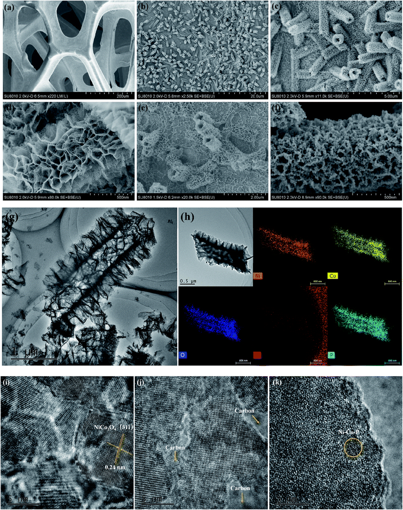
The overall synthetic strategy involves several steps, as illustrated in Scheme 1. NF with macropores and 3D conductive network was adopted as the substrate for the growth of electrocatalyst (Fig. 1a). First, hierarchical tetragonal microtubes consisting of ultrathin mesoporous NiCo2O4 nanosheets was deposited on NF by a one-step solvothermal method (Fig. 1b). The above Ni–Co–O/NF precursor was immersed in the glucose solution and annealed in nitrogen atmosphere, subsequently, amorphous carbon was anchored to the Ni–Co–O/NF surface to obtain Ni–Co–O–C/NF (Fig. 1e). Finally, Ni–Co–O–C–P/NF was obtained by a phosphorization process with NaH2PO2 at under argon condition (Fig. 1f). The XRD techniques proved the successful synthesis of Ni–Co–O–C–P/NF. When further increasing the amount of carbon or P coating mass, the surface of tetragonal hollow microtubes changes remarkably (Fig. S1†).The morphology and structure of the as-prepared Ni–Co–O–C–P/NF were characterized by the scanning electron microscopic (SEM) and TEM measurements. As shown in Fig. 1a, the pristine Ni foam exhibits 3D interconnected open macropores with the size distribution among the range of 200–500 μm. Fig. 1b indicates the hollow NiCo2O4 tetragonal microtubes evenly cover the surface of the 3D foamed nickel. It can be seen that the as prepared NiCo2O4 are uniform in size, about 1–2 μm in length and about 500 nm in width, possessing hollow tetragonal microtubes morphology with two open ends. The enlarged view of an individual tube (Fig. 1d) shows that the tetragonal microtubes is constructed by randomly oriented sheet-like subunits with a thickness around several nanometers. More importantly, numerous interparticle mesopores are uniformly distributed throughout the nanosheet. The unique open and hierarchical nano-architectures endow the microtubes with abundant open space and sufficient electrode/electrolyte contact area for electrochemical reactions. As shown in Fig. 1e, the formed Ni–Co–O–C/NF maintains the structure well after carbon coating and heat treatment process. However, the surface morphology changes remarkably with the increase of carbon coating mass (Fig. S1d†). After in situ phosphorization process, the hollow tetragonal microtubes morphology is still maintained (Fig. 1g), however, the nanosheet is changed to nanoparticles. EDX elemental mapping (Fig. 1h) not only confirms the presence of Ni, Co, O, C and P elements but also proves a homogeneous distribution of the Ni, Co, O, C and P elements throughout the whole Ni–Co–O–C–P/NF. The HRTEM image (Fig. 1i) shows clear lattice fringes with an interplanar spacing of 0.24 nm, corresponding to the (111) plane of the NiCo2O4. It is also interesting to see that the carbon layer forms a coating at the outer edge (Fig. 1j), which can not only maintain the structural integrity, but also improves the conductivity. The metallic phosphides particles were distributed throughout the whole Ni–Co–O–C–P/NF electrocatalysis (Fig. 1k).
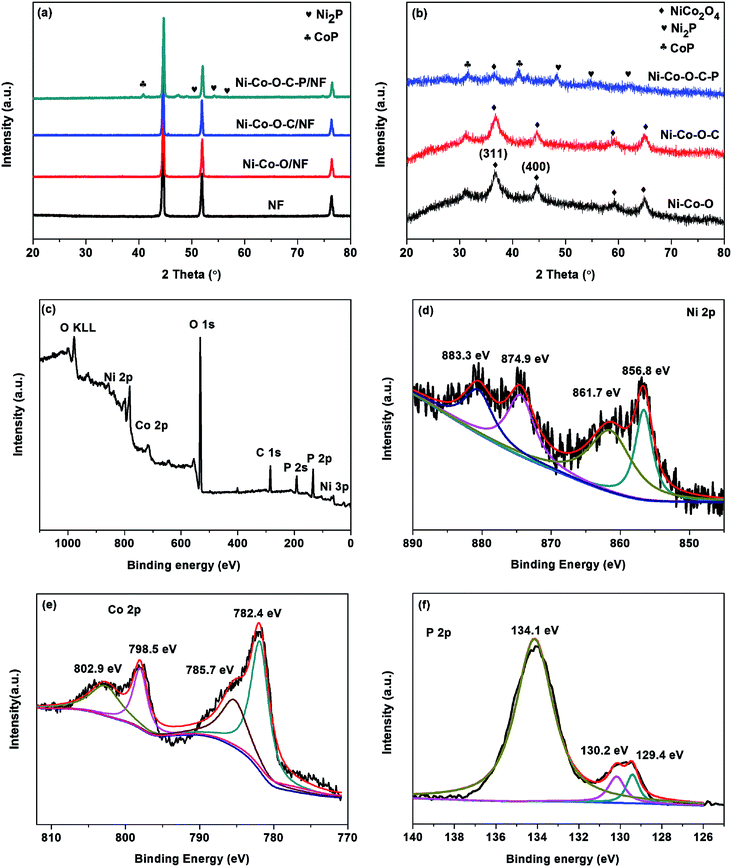
Fig. 2a shows the XRD patterns of the 3D Ni foam supported samples are almost the same. The peaks at 44.8, 52.2 and 76.8 can be indexed to the diffractions of (111), (200) and (220) planes of NF substrate.16 Except for the diffractions of NF substrate, no other diffraction peaks appear. This might be due to the hierarchical tetragonal microtubes form a highly open network structure, which permits the X-rays to penetrate easily through the array down to the substrate.37 And the diffraction peaks of the NF substrate are much stronger than that of Ni–Co–O/NF, Ni–Co–O–C/NF and Ni–Co–O–C–P/NF. In order to prevent the impact of the NF substrate, we scraped the coating on the surface of the electrode and the XRD diffraction peaks are shown in Fig. 2b. The NiCo2O4 was transformed into CoP and Ni2P successfully after in situ phosphorization process. And there is no other impurity peak can be observed, indicating the good crystallinity and high purity of CoP and Ni2P.
X-ray photoelectron spectroscopy (XPS) measurements are performed to further confirm the chemical compositions and oxidation states of the Ni–Co–O–C–P/NF. As illustrated in Fig. 2c, the survey XPS spectrum shows the peaks of Ni, Co, O, P and C elements, which is consistent with the result of TEM mapping analysis. In the Ni 2p region (Fig. 2d), the binding energies appeared at 856.8 and 874.9 eV as well as the corresponding satellite peaks at 861.7 and 883.3 eV, revealing the formation of oxidized nickel species.26 As presented in Co 2p spectrum, the peak at 782.4 eV for Co 2p3/2 corresponds to Co species in the Co–P compound. The peak at 785.7 eV can be ascribed to the oxidized Co species. The corresponding satellite peaks of Co 2p3/2 and Co 2p1/2 are situated at 798.5 and 802.9 eV, respectively.33 Fig. 2f shows the P 2p emission spectrum, which can be split into peaks at binding energies of 129.4 and 130.2 eV corresponding to P 2p3/2 and P 2p1/2, which can be assigned to reduced phosphorus in the form of metal phosphides. The peak at 134.1 eV is assigned to phosphate species (P5+) resulting from the exposure of the product to air.34
The surface area and pore size of the Ni–Co–O–C–P/NF are determined by N2 sorption measurements, as shown in Fig. S2(b).† However, the adsorption of N2 is not feasible for 3D porous Ni foam due to the too large pores, therefore, N2 adsorption measurements of NiCo2O4 powder was further performed (Fig. S2a†). The Brunauer–Emmett–Teller (BET) surface area and total pore volume of NiCo2O4 powder are measured to be 151.2 m2 g−1 and 0.534 cm3 g−1, respectively. The corresponding pore size distribution data show that the size of the majority of pores falls in the range of 2–10 nm. Clearly, there are three kinds of porosities within the hierarchical NiCo2O4 hollow tetragonal microtubes, including the micropores and mesopores among the oriented stacking nanosheets as well as the macropores derived from the open and hollow interior. The highly specific surface area and porous structure not only ensure the exposure of active sites but also promote the penetration of electrode/electrolyte contact area, which is expected to facilitate the electrochemical reactions.
3.2. Catalytic performance for HER
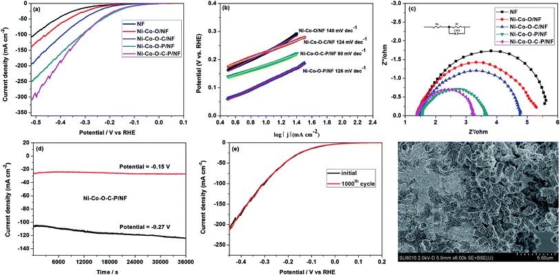
The HER performance of the as prepared catalysts was evaluated in alkaline media (1 M KOH) with a three-electrode system (Fig. 3). In comparison with Ni–Co–O/NF, the LSV curves of Ni–Co–O–C/NF, Ni–Co–O–P/NF, Ni–Co–O–C–P/NF electrodes are shifted obviously to the positive direction and Ni–Co–O–C–P/NF shows the best HER activity among all these electrodes. It is also shown that the HER activity of Ni–Co–O–C–P/NF is increased with P content, and further increasing the P content fails to enhance its HER activity any more (Fig. S3a†). Specifically, the overpotential at 10, 20, and 100 mA cm−2 for Ni–Co–O–C–P/NF is −119, −165 and −309 mV, respectively, which is comparable to most of the recently reported Ni–Co–P catalysts (Table S1†). In contrast, the overpotential required to drive the current density of 10 mA cm−2 is −274 mV for NF, −234 mV for Ni–Co–O/NF, −195 mV for Ni–Co–O–C/NF, and −113 mV for Ni–Co–O–P/NF. The as-prepared Ni–Co–O–P/NF shows comparable HER activity to Ni–Co–O–C–P/NF. The HER performance of Ni–Co–O–C–P/NF in 0.1 M and 30 wt% KOH was shown in Fig. S7(a).†The reaction kinetics of HER can be analyzed by using Tafel plots: η= a + b log![[thin space (1/6-em)]](https://www.rsc.org/images/entities/char_2009.gif) j, where j and b stands for the measured current density (mA cm−2) and Tafel slopes, respectively. Fig. 3b illustrates the Tafel slope of the Ni–Co–O–C–P/NF is approximately 90 mV dec−1, which is considerably lower than that of Ni–Co–O/NF (ca. 140 mV dec−1), Ni–Co–O–C/NF (ca. 124 mV dec−1), Ni–Co–O–P/NF (ca. 126 mV dec−1). The value of Tafel slope is closely related to the kinetics of HER. According to the previous literatures, the mechanism of HER in alkaline medium was Volmer–Heyrovsky process or Volmer–Tafel pathways. All the Tafel slopes of the as prepared catalysts are in range of 40–130 mV dec−1 which implies that the HER may followed the Volmer–Heyrovsky mechanism with the Heyrovsky reaction as the rate determining step.14
j, where j and b stands for the measured current density (mA cm−2) and Tafel slopes, respectively. Fig. 3b illustrates the Tafel slope of the Ni–Co–O–C–P/NF is approximately 90 mV dec−1, which is considerably lower than that of Ni–Co–O/NF (ca. 140 mV dec−1), Ni–Co–O–C/NF (ca. 124 mV dec−1), Ni–Co–O–P/NF (ca. 126 mV dec−1). The value of Tafel slope is closely related to the kinetics of HER. According to the previous literatures, the mechanism of HER in alkaline medium was Volmer–Heyrovsky process or Volmer–Tafel pathways. All the Tafel slopes of the as prepared catalysts are in range of 40–130 mV dec−1 which implies that the HER may followed the Volmer–Heyrovsky mechanism with the Heyrovsky reaction as the rate determining step.14
| Volmer reaction: H2O + e → Hads + OH−; | (1) |
| Heyrovsky reaction: Hads + H2O → H2 + OH−; | (2) |
| Tafel reaction: Hads + Hads → H2; | (3) |
The Nyquist plots of the as-prepared samples in 1.0 M KOH are shown in Fig. 3c and S3† to study this difference on catalytic activity. For Ni–Co–O–C–P/NF, Rct is around 11 ohm at a lower overpotential of 144 mV, and it decreases to 1.6 ohm as the overpotential reaches −244 mV. The value of the Rct drops to 1.5 ohm at −344 mV and −444 mV, showing that the charge transfer kinetics were significantly improved by increasing overpotential (Fig. S3†). The small semicircular diameter with increased overpotential indicates a considerable low charge-transfer resistance (RCT). The integrated electrode configuration of Ni–Co–O–C–P hollow tetragonal microtubes directly grown on Ni foam effectively enhances electron/charge transfer at the interface of electrodes and electrolyte. Also, as shown in Fig. 3c, the smaller diameter of the semicircle of the Ni–Co–O–C–P/NF suggests transfer impedance of contact and charge smaller than other samples.
Except for HER activity, stability is another important factor to evaluate the performance of electrocatalyst. The durability of Ni–Co–O–C–P/NF was evaluated by a potentiostatic testing under an overpotential of −150 mV, and no obvious decline of the current density was observed in a period of 10 h. When the given potential increased to −270 mV, the current density decreased by about 13% in a period of 10 h (Fig. 3d). After another dynamic potential testing for cycling 1000 times, only < 10 mV variation in overpotential was observed on the LSV curve (Fig. 3e). The SEM technique confirms that the tetragonal microtubes morphology was well maintained but the open ends were closed after hydrogen evolution for 10 h with an overpotential of −270 mV (Fig. 3f).
3.3. Catalytic performance for OER
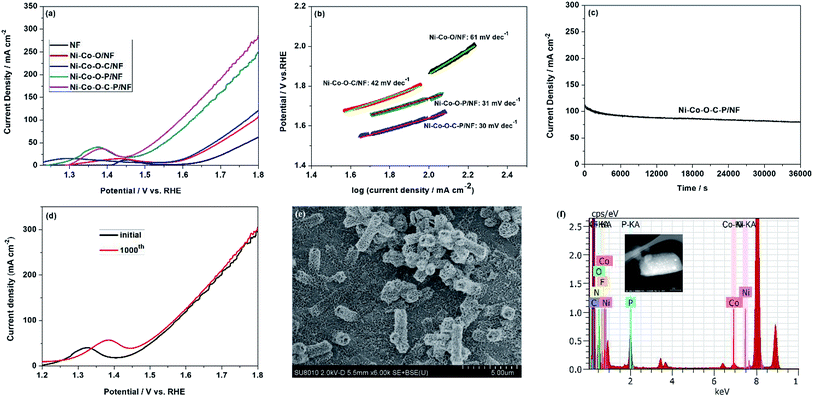
The electrocatalytic performance of the Ni–Co–O–C–P for OER was also evaluated by using a standard three-electrode cell in 1.0 M KOH solution. According to the LSV curves, the Ni–Co–O–C–P/NF shows more negative potential and higher current density in comparison with other samples. As shown in Fig. 4a, in order to achieve a current density of 100 mA cm−2, Ni–Co–O–C–P/NF requires an overpotential of 340 mV, lower than Ni–Co–O–C/NF (570 mV) and Ni–Co–O–P/NF (390 mV). The OER performance of Ni–Co–O–C–P/NF in 0.1 M and 30wt% KOH was shown in Fig. S7(b).† The result is in accordance with other reported bimetallic phosphide materials (Table S2†). Previous studies have demonstrated that formed bimetallic phosphide catalyst can make the d-band center closer to Fermi level and lead to stronger binding interaction between the adsorbates and catalyst.38 It can modulate the binding energies of the intermediates towards optimal value and thus benefiting OER.39The enhanced OER performance of the Ni–Co–O–C–P/NF is further confirmed by a smaller Tafel slope compared with that of the nanosheets as revealed in Fig. 4b, indicating a favorable OER kinetics in the Ni–Co–O–C–P/NF. The long-term durability of the Ni–Co–O–C–P/NF for OER was tested by a chronoamperometry measurement (Fig. 4c). The current density exhibits slight attenuation after duration of continuous OER test. After dynamic potential testing for cycling 1000 times, about 50 mV variation in overpotential was observed on the LSV curve (Fig. 4d). The SEM images of Ni–Co–O–C–P/NF indicated that the open nano-architectures was destroyed after long-term durability (Fig. 4e). The EDS analysis confirmed the presence of Ni, Co, O, C and P element after long-term durability test for OER (Fig. 4f). The XPS analysis of Ni–Co–O–C–P/NF after OER reaction (Fig. S6†) confirms that the formed oxides/hydroxides during OER process is helpful for its superior OER electrocatalytic activity, which agrees well with previous reports.41
3.4. Overall water splitting reaction
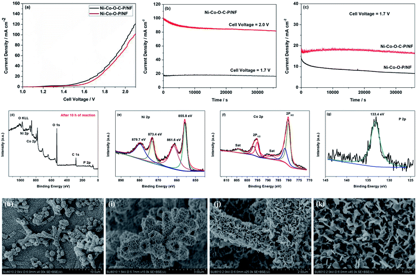
As mentioned above, the Ni–Co–O–C–P/NF can employ as the cathode for HER and the anode for OER. Therefore, the overall water splitting measurement is carried out in a two-electrode cell by employing Ni–Co–O–C–P/NF as both anode and cathode.The Ni–Co–O–C–P/NF couple exhibits high activity for overall water splitting reaction. The iR-corrected polarization curves presented in Fig. 5a show that the cell voltage of Ni–Co–O–C–P/NF couple at 10, 20 and 100 mA cm−2 is 1.50, 1.65, and 2.0 V, respectively, while the potential needs to rise to 1.63, 1.72 and 2.10 V to reach the same current density in the case of the Ni–Co–O–P/NF. The overall water splitting performance is comparable to most of the recently reported Ni–Co–P based catalysts (Table S3†).
Stability is another vital parameter for the evaluation of electrocatalysts. The long-term durability test for overall water splitting is conducted by a chronoamperometry measurement. Remarkably, as presented in Fig. 5b, the Ni–Co–O–C–P/NF are stable over 10 h with the current loss of only 3.6% for overall water splitting at the cell potential of 1.70 V. When the given cell voltage increased to 2.0 V, the current density decreased by about 15% in a period of 10 h (Fig. 5b). Fig. 5c illustrates that the carbon coating plays an important role for long long-term durability of the electrocatalyst. For Ni–Co–O–C–P/NF, the current loss is only 3.6% for overall water splitting at the cell potential of 1.70 V, as a comparison, for Ni–Co–O–P/NF, the current loss is almost 50%. Conductive carbon materials not only promote the charge transfers but also enhance the structure stability.
Fig. 5d–g shows the XPS spectrum of Ni–Co–O–C–P/NF (anode) after long-term durability test with a cell potential of 2.0 V. The survey XPS spectrum confirms the presence of Ni, Co, O, C and P element after long-term durability test for overall water splitting reaction (Fig. 5d). For the Ni 2p region (Fig. 5e), the peaks at 855.8 eV and 873.4 eV along with two satellite peaks at 861.6 and 879.7 are attributed to Ni 2p3/2 and Ni 2p1/2 of the oxidized nickel species, respectively.14 For Co 2p spectrum (Fig. 5f), the two main peaks at 779.8 and 795.0 eV are assigned to Co 2p3/2 and Co 2p1/2 of metallic cobalt. In addition, the peak at 782.0 eV in the Co 2p3/2 region and 797.3 eV in the Co 2p1/2 region are assigned to oxidized Co species (Co2+/3+). The peaks at 787.9 and 804.1 eV are according to the corresponding satellite peaks of Co 2p3/2 and Co 2p1/2.26 Fig. 5g shows the P 2p emission spectrum, a broad feature at approximately 133.4 eV is assigned to phosphate.33 The XPS analysis also confirms that the formed oxides/hydroxides during oxygen evolution process which agrees well with previous reports.41
Fig. 5h and i show the SEM images of cathode after long-term durability test in overall water splitting reaction. It can be seen that the nano-architectures is still maintained as hollow tetragonal microtubes, but the open ends shrink a lot. As shown in Fig. 5j and k, for anode, the ultrathin nanosheet subunits thicken a lot after long-term durability test in overall water splitting reaction and the mesopores throughout the nanosheet was disappeared. Therefore, the current loss for overall water splitting was attributed to the reduction of specific surface area and loss of mesopores which could decrease the electrode/electrolyte contact area and difficult the mass transport.
Scheme 2 illustrates a two-electrode configuration of Ni–Co–O–C–P/NF for overall water splitting in alkaline media. The excellent catalytic performance for overall water splitting of Ni–Co–O–C–P/NF can be attributed to the following four factors: (i) the unique hierarchical 3D open and hollow nano-architectures assembled from ultrathin mesopores nanosheet provides high electrochemical active surface area, abundant catalytic sites, excellent diffusion and mass transport properties, effective penetration of the electrolyte, and easy releasing of the evolved gas bubbles. (ii) The good structural stability and excellent electrical conductivity was ensured by the coating carbon layer. The carbon coating on the surface can enhance the electronic conductivity and support the structural flexibility in alkaline environments. In addition, the interconnected mesopores nanosheet also helps to maintain good mechanical and electrical contacts. (iii) The self-supported property of Ni–Co–O–C–P and NF eliminates the interfacial overpotential between them. Fig. S5† indicates that Ni foam supported Ni–Co–O–C–P shows the best electrochemical performance among different supports (including carbon cloth, Ti mesh, Cu foam and Ni foam).42,43 The smaller diameter of the Nyquist plots of Ni–Co–O–C–P/NF suggests transfer impedance of contact and charge smaller than other supports. Therefore, suitable support also plays an important role for the excellent electrocatalytic performance. (iv) Ni2P and CoP intrinsically possesses bifunctional catalytic sites suitable for both HER and OER.
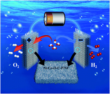 | ||
| Scheme 2 Schematic illustration of a two-electrode configuration of Ni–Co–O–C–P/NF for overall water splitting in alkaline media. | ||
4. Conclusions
In summary, a bifunctional electrocatalyst in the form of tetragonal microtubes grown on 3D Ni foam presented high performances for both HER and OER in alkaline media. The as-prepared Ni–Co–O–C–P/NF exhibit high electrocatalytic activity, which affords the current density of 10 mA cm−2 at low overpotentials for oxygen and hydrogen evolution reactions respectively, and well stability in an alkaline medium. The overall-water-splitting reaction requires a low cell voltage (1.54 V @ 10 mA cm−2) in 1 M KOH when Ni–Co–O–C–P/NF was used as both the anode and cathode. The excellent catalytic performance for overall water splitting of Ni–Co–O–C–P/NF can be attributed to the highly flexible open nano-architectures, the synergetic effect of bimetallic phosphides, and the enhanced electronic conductivity by carbon coating. This work demonstrated a promising bifunctional electrocatalyst for water electrolysis in alkaline media with potential application in the future.Conflicts of interest
There are no conflicts to declare.Acknowledgements
This work was supported by the Hubei Provincial Natural Science Foundation of China (2018CFB228, 2018CFB237), National Natural Science Foundation of China (21806187, 51802357), Fundamental Research Funds for the Central Universities (CZT19004, CZT19003) Australian Research Council (ARC) (DE190100504).References
- M. D. Krcha, K. M. Dooley and M. J. Janik, J. Catal., 2015, 330, 167–176 CrossRef CAS.
- J. W. Li, Q. N. Zhuang, P. M. Xu, D. W. Zhang, L. C. Wei and D. S. Yuan, Chin. J. Catal., 2018, 39, 1403–1410 CrossRef CAS.
- J. T. Li, G. Q. Du, X. Cheng, P. J. Feng and X. T. Luo, Chin. J. Catal., 2018, 39, 982–987 CrossRef CAS.
- F. Li, H. Li, Y. Zhu, J. Du, Y. Wang and L. C. Sun, Chin. J. Catal., 2017, 38, 1812–1817 CrossRef CAS.
- R. C. Shen, J. Xie, Q. J. Xiang, X. B. Chen, J. Z. Jiang and X. Li, Chin. J. Catal., 2019, 40, 240–288 CrossRef CAS.
- Z. Li, Y. N. Ma, X. Y. Hu, E. Z. Liu and J. Fan, Chin. J. Catal., 2019, 40, 434–445 CrossRef CAS.
- Y. M. Li and R. Nakamura, Chin. J. Catal., 2018, 39, 401–406 CrossRef CAS.
- X. Q. Ji, B. P. Liu, X. Ren, X. F. Shi, A. M. Asiri and X. P. Sun, ACS Sustainable Chem. Eng., 2018, 6, 4499–4503 CrossRef CAS.
- X. Q. Ji, R. Zhang, X. F. Shi, A. M. Asiri, B. Z. Zheng and X. P. Sun, Nanoscale, 2018, 10, 7941–7945 RSC.
- P. P. Li, R. B. Zhao, H. Y. Chen, H. B. Wang, P. P. Wei, H. Huang, Q. Liu, T. S. Li, X. F. Shi, Y. Y. Zhang, M. L. Liu and X. P. Sun, Small, 2019, 15, 1805103 CrossRef PubMed.
- T. T. Liu, L. S. Xie, J. H. Yang, R. M. Kong, G. Du, A. M. Asiri, X. P. Sun and L. Chen, ChemElectroChem, 2017, 4, 1840–1845 CrossRef CAS.
- Q. Liu, L. S. Xie, Z. A. Liu, G. Du, A. M. Asiri and X. P. Sun, Chem. Commun., 2017, 53, 12446–12449 RSC.
- Z. Q. Wang, X. Ren, L. Wang, G. W. Cui, H. J. Wang and X. P. Sun, Chem. Commun., 2018, 54, 10993–10996 RSC.
- M. I. Jamesh, J. Power Sources, 2016, 213–236 CrossRef CAS.
- G. Zhang, Y. S. Feng, W. T. Lu, D. He, C. Y. Wang and F. F. Cao, ACS Catal., 2018, 8(6), 5431–5441 CrossRef CAS.
- Q. Q. Jiang, Y. F. Lu, Z. X. Huang and J. C. Hu, Appl. Surf. Sci., 2017, 402, 277–285 CrossRef CAS.
- S. Hu, Q. Q. Jiang, S. P. Ding, Z. Z. Wu, Z. X. Huang, T. F. Zhou, Z. P. Guo and J. C. Hu, ACS Appl. Mater. Interfaces, 2018, 10, 25483–25492 CrossRef CAS PubMed.
- H. Vrubel and X. L. Hu, Angew. Chem., Int. Ed., 2012, 51, 12703–12706 CrossRef CAS PubMed.
- T. Zhang, K. N. Yang, C. Wang and L. Fu, Adv. Energy Mater., 2018, 1801690 CrossRef.
- Y. R. Liu, Y. M. Du, W. K. Gao, B. Dong, Y. Han and L. Wang, Electrochim. Acta, 2018, 290, 339–346 CrossRef CAS.
- E. L. Hu, Y. F. Feng, J. W. Nai, D. Zhao, Y. Hu and X. W. Lou, Energy Environ. Sci., 2018, 11, 872–880 RSC.
- C. J. Xuan, J. Wang, W. W. Xia, J. Zhu and D. L. Wang, J. Mater. Chem. A, 2018, 6, 7062–7069 RSC.
- Y. Nie, L. Li and Z. Wei, Chem. Soc. Rev., 2015, 46, 2168–2201 RSC.
- X. Tian, H. Tang, J. Luo, H. Nan, T. Shu, S. Liao and R. R. Adzic, ACS Catal., 2017, 7, 3810–3817 CrossRef CAS.
- Q. Wang, Z. Y. Zhou, Y. J. Lai, Y. You, J. G. Liu, X. L. Wu, C. Chen and S. G. Sun, J. Am. Chem. Soc., 2014, 136, 10882–10885 CrossRef CAS PubMed.
- J. Meng, C. Niu, X. Liu, Z. Liu, H. Chen, X. Wang, J. Li, W. Chen, X. Guo and L. Mai, Nano Res., 2016, 9, 2445–2457 CrossRef CAS.
- F. L. Yang, Y. T. Chen, G. Z. Cheng, S. L. Chen and W. Luo, ACS Catal., 2017, 7, 3824–3831 CrossRef CAS.
- N. Jiang, B. You, M. L. Sheng and Y. J. Sun, Angew. Chem., Int. Ed., 2015, 54, 6251–6254 CrossRef CAS PubMed.
- Y. P. Zhu, Y. P. Liu, T. Z. Ren and Z. Y. Yuan, Adv. Funct. Mater., 2015, 25, 7337–7347 CrossRef CAS.
- T. Sun, L. Xu, Y. Yan, A. A. Zakhidov and R. H. Baughman, ACS Catal., 2016, 6, 1446–1450 CrossRef CAS.
- X. Liu, M. Park, M. G. Kim, S. Gupta, G. Wu and J. Cho, Angew. Chem., Int. Ed., 2015, 54, 9654–9658 CrossRef CAS PubMed.
- J. X. Feng, S. H. Ye, H. Xu, Y. X. Tong and G. R. Li, Adv. Mater., 2016, 28, 4698–4703 CrossRef CAS PubMed.
- Y. Pan, Y. R. Liu, J. C. Zhao, K. Yang, J. L. Liang, Y. Q. Liu and C. G. Liu, J. Mater. Chem. A, 2015, 3, 1656–1665 RSC.
- J. Y. Li, M. Yan, X. M. Zhou, Z. Q. Huang, Z. M. Xia, C. R. Chang, Y. Y. Ma and Y. Q. Qu, Adv. Funct. Mater., 2016, 26, 6785–6796 CrossRef CAS.
- V. Vij, S. Sultan, A. M. Harzandi, A. Meena, J. N. Tiwari, W. G. Lee, T. Yoon and K. S. Kim, ACS Catal., 2017, 7, 7196–7225 CrossRef CAS.
- Y. Pan, K. A. Sun, S. J. Liu, X. Cao, D. S. Wang, C. Chen and Y. D. Li, J. Am. Chem. Soc., 2018, 140, 2610–2618 CrossRef CAS PubMed.
- J. Yang, F. J. Zhang, X. Wang, D. S. He, G. Wu, Q. H. Yang, Y. Wu and Y. D. Li, Angew. Chem., Int. Ed., 2016, 55, 12854–12858 CrossRef CAS PubMed.
- X. C. Yin, G. Sun, L. Su, L. X. Wang and G. J. Shao, Electrochim. Acta, 2018, 284, 226–233 CrossRef CAS.
- Q. Liu, J. Tian, W. Cui, P. Jiang, N. Cheng, A. M. Asiri and X. Sun, Angew. Chem., Int. Ed., 2014, 53, 6710–6714 CrossRef CAS PubMed.
- L. Ma, X. Shen, H. Zhou, G. Zhu, Z. Ji and K. Chen, J. Mater. Chem. A, 2015, 3, 5337–5343 RSC.
- C. Tang, N. Y. Cheng, Z. H. Pu, W. Xing and X. P. Sun, Angew. Chem., Int. Ed., 2015, 54, 9351–9355 CrossRef CAS PubMed.
- W. X. Zhu, R. Zhang, F. L. Qu, A. M. Asiri and X. P. Sun, ChemCatChem, 2017, 9, 1721–1743 CrossRef CAS.
- Q. Liu, A. M. Asiri and X. P. Sun, Electrochem. Commun., 2014, 49, 21–24 CrossRef CAS.
Footnotes |
| † Electronic supplementary information (ESI) available. See DOI: 10.1039/c9ra05165a |
| ‡ Wenjing Hu and Qingqing Jiang contributed equally to this work. |
| This journal is © The Royal Society of Chemistry 2019 |


