 Open Access Article
Boosting the performance of broccoli-like Ni-triazole frameworks through a CNTs conductive-matrix†
Kuaibing Wang a,
Huijian Wanga,
Yang Chua,
Aimin Lua,
Feifei Mao
 a,
Zikai Wangac,
Mingbo Zhengb and
Hua Wu
 *a
*a
aJiangsu Key Laboratory of Pesticide Sciences, Department of Chemistry, College of Sciences, Nanjing Agricultural University, Nanjing 210095, P. R. China. E-mail: wuhua@njau.edu.cn
bSchool of Chemistry and Chemical Engineering, Institute for Innovative Materials and Energy, Yangzhou University, Yangzhou, 225009, Jiangsu, P. R. China
cCollege of Resources and Environmental Sciences, Nanjing Agricultural University, Nanjing 210095, P. R. China
First published on 15th August 2019
Abstract
Different approaches for the fabrication of CNT-supported Ni-triazole composites, such as room-temperature stirring and hydrothermal treatment for a distinct reaction time has been presented. As a result, various morphologies, MMOF wrapped CNTs, CNTs entangled with an MMOF and CNTs attached on an MMOF, were synthesized and investigated through electrochemical measurements. The as-synthesized CNTs/MMOF-based hybrids, especially for the CNTs/MMOF-8H structure, show a good rate capability after 20 times increase, a superior coulombic efficiency and an excellent long-term cycling stability (more than 98% retained after 2000 cycles). This enhancement can be ascribed to the introduction of the CNT conductive additives, which promote the fast charge-transfer ability of ions and electrons. Even for the other CNTs/MMOF-based composites, the overall electrochemical performances are still superior to those of pristine MMOF electrodes.
Introduction
Metal–organic frameworks (MOFs) possessing high surface areas, topological structures and controllable cavity sizes have attracted extensive attention in catalysis, sensors, gas storage, drug delivery etc.1–3 Besides, MOFs and MOF-derived inorganic materials are receiving an increasing focus in energy-storage fields, such as supercapacitors (SCs) and lithium ion batteries (LIBs).4–6 In contrast with LIBs, SCs not only store equal energy but also provide the high power needed which can recharge in seconds.Although the limitations of the poor conductivity and instability exists in MOF-based SCs electrodes, the specific capacitance value is remarkable due to the similar redox mechanism to metal-oxides-based pseudocapacitors.7–12 For instance, Wei's group fabricated a two-dimensional (2D) Ni-based MOFs electrode delivering high capacitance of 1127 F g−1 at a current density of 0.5 A g−1.8 Liu prepared a layered Co-MOFs electrode displaying a high capacitance of 2474 F g−1 at 1.0 A g−1.9 Wang and co-workers also synthesized a topological 3D Co-MOFs electrode and obtained a maximum capacitance of 2572 F g−1 at 2.0 A g−1.10 This pseudo-capacitive behavior makes them serving as new candidates for applying in SCs fields to date.
A strategy, compositing with carbon-based materials, is forward up to avoid the drawbacks of MOFs SCs electrodes in recent years.13–19 Carbon-based materials, such as carbon nanotubes (CNTs), graphene, mesoporous carbon and whatnot, are usually used to wrap up metal oxides or inorganic particles with weak-conductivity.20–25 For example, Brown20 group found that the synergy and optimization of CNTs can result in a high gravimetric capacitance of 640 F g−1 at high MnO2 specific loading. Furthermore, Zhou26 prepared graphene oxide (GO) and CNTs co-compositing conducting polymer to further improve the conductivity of the final electrode materials. The obtained PEDOT-GO/CNTs ternary composites displayed a high areal specific capacitance of 99 mF cm−2 at 1.0 mA cm−2 and excellent cycle stability of 99.2% after 5000 continuous cycles.
The departure point of this strategy is to improve the conductivity of MOFs, resembling the strategy of self-strengthening conductivity.27,28 The self-strengthening method is fabricating conducting ligand to react with metal ions to construct 2D MOFs. However, it is hard to choose and prepare polycyclic aromatic compound and not to mention to synthesize the 2D MOFs with concrete single-crystal structure. On the other hand, introduction of carbon materials could occur a synergistic effect and optimize composite structure through self-supported high surface area and porous structure and thus more beneficial to ions and electron transport. Interestingly however, the introduction of carbon-based materials influencing or altering the structures of the hybrids is scarce to be mentioned. Herein, controllable synthesizing CNTs-supported MOFs with various morphologies have been investigated through adjusting reaction parameters. Consequently, MMOF wrapped CNTs, CNTs entangled with MMOF and CNTs attached on MMOF, have been synthesized and directly used as SCs electrodes.
Experimental
Synthesis of Ni-triazole microstructures (MMOF)
Solvents and all other chemicals were obtained from commercial sources and used as received unless otherwise noted. The nitrogen-rich carboxylate 3-amino-1,2,4-triazole-5-carboxylic acid hemihydrate (ATC, 0.3202 g) was weighed and dissolved in deionized water with the assistance of NaOH (0.1 g) to form ATCNa aqueous solution (ca. 0.05 M). In a typical synthesis of MMOF, 0.05 M ATCNa (12 mL) aqueous solution was introduced into 0.05 M Ni(OAc)2 (6 mL) aqueous solution drop by drop in co-solvent mixture (water/ethanol: 20/20, v/v) under unceasing stirring for 12 h, and the resulting green precipitate was collected by centrifugation, and washed several times with ethanol and water to remove un-bonded reactants and byproducts. Then the powder product was dried in an oven at 40 °C for 12 h and denoted as MMOF for convenient description. Elemental analysis (EA) for MMOF: C, 21.99; H, 2.51; N, 35.03%. IR (KBr pellet, cm−1): 3368 s, 3238 w, 1582 s, 1508 s, 1480 s, 1435 s, 1377 s, 1290 s, 1122 m, 1058 m, 890 m, 828 m, 814 m, 726 s, 646 m, 602 w, 519 s, 462 w, 435 s.Synthesis of CNTs-supported MMOF composites
For synthesis of CNTs/MMOF composites, carbon nanotubes (CNTs, 0.02 g) and the additive polystyrene sulfonate sodium (PSS, 0.6 mL) were introduced into the above-mentioned MMOFs system under the same reaction time and the same post-treatment methods. For comparison, the mixed compounds were placed in a Teflon reactor (100 mL) and heated at 120 °C for one hour and eight hours and labeled as CNTs/MMOF-1H and CNTs/MMOF-8H, respectively.Methods and measurements
FT-IR spectra were recorded from KBr pellets in range 4000–400 cm−1 on a Nicolet 380FT-IR spectrometer. The elemental analyses of C, H, and N were performed on an Elementar Vario MICRO Elemental Analyzer. X-ray powder diffraction (XRD) data were collected on a Bruker D8 Advance instrument using CuKα radiation (λ = 1.54056 Å) at room temperature. The morphologies of the as-prepared samples were obtained by using a Hitachi S-8100 field-emission scanning electron microscope (FE-SEM).The detailed electrode preparation process can be found in our previous work.10,11 The electrochemical data compilation were carried out through CHI660E (Chenhua Instrument, Shanghai, China) in a three-compartment cell with a platinum plate counter electrode, a Hg/HgO electrode reference electrode and a working electrode. The electrolyte was a 6 M KOH aqueous solution and the resistance data were collected using electrochemical impedance spectroscopy (EIS) method at open circuit voltage in the frequency range of 100 kHz to 10 mHz. Notably, typical mass load of electrode materials ranged in 2.0–4.3 mg after pressed by Manual Rolling Press (MR-100A).
Results and discussion
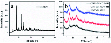
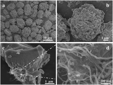
In a typical experiment, MMOF have been firstly synthesized through a simple coordination method. Its structure is characterized by X-ray powder diffraction (XRD) as shown in Fig. 1a. All the diffraction peaks are strong and sharp indicating well-crystallized nature after 12 hours of reaction. It is noteworthy that the crystal structure of MMOF cannot correspond to any known phase of Ni-triazole-based MOFs (based on the search results from CCDC22) and it suggests MMOF is a new structure. Therefore, the elemental analysis (EA) and IR spectrometry were adopted to further detect the structure (details seen Experimental section). The characteristic bands in MMOF centered at 1480–1582 cm−1 can be assigned for anti-symmetric stretching of carboxylate group and 1377–1435 cm−1 belongs to symmetric stretching. The absence of the fixed bands centered at 1685–1715 cm−1 for the protonated carboxylate group indicates the occurrence of coordination reaction.29 However, the diffraction peaks alter into broad type when carbon nanotubes merged into MMOF system as depicted in Fig. 1b. Whether adding CNTs through hydrothermal method or room-temperature stirring, the structure keeps unchanged except of the crystallinity. Correspondingly, the introduction of CNTs weakens the crystallinity of MMOF indicating the alternation of the microscopic structure.This alternation can be confirmed from the SEM image of as-synthesized MMOF and CNTs/MMOF-based samples. Fig. 2a shows the SEM images of MMOF. The broccoli-like clusters are constructed by various ragged blocks and these blocks hierarchically aggregated together as displayed in Fig. 2b. By contrast, CNTs/MMOF, synthesized from the same condition as MMOF, shows an agglomerate motif that the MMOF blocks wrap the CNTs inside (Fig. 2c). The CNTs arrays are entangled together with mean width of 20 nm (Fig. 2d).
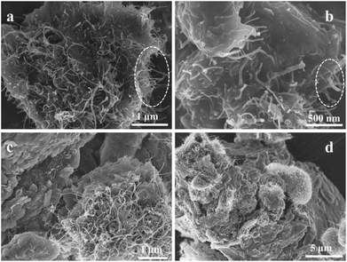
When the reaction temperature changed from room temperature into 120 °C under hydrothermal condition, the different exterior morphology was obtained as vividly shown in Fig. 3. The CNTs and MMOF materials display in a state of intergrowth at the hydrothermal time of 1 hour (Fig. 3a and b). In other words, CNTs and sheet-like MMOF were wrapped up or entangled together to form a bulk motif. Interestingly however, the CNTs materials grow along the “MMOF cliff” to form a moss-analogue attachment at 8 hours. In this motif, the surface of MMOF is tighter and the bulk MMOF is larger due to the longer growing period (Fig. S1†). This growing direction is just opposite to that of the CNTs/MMOF at room temperature (Fig. 3c and d).
Due to the discrepancy of the morphology caused from introduction of CNTs, the electrochemical performances could have distinct results for the as-synthesized samples. The electrochemical properties of as-prepared MOF-based products were investigated by directly applying them as the active electrode materials for SCs. The first difference is mainly focused on the integral area which were measured through cyclic voltammetry (CV) within the potential window in 0–0.6 V. The obtained CV curves for as-prepared MMOF and CNTs/MMOF-based electrodes are shown in Fig. 4. Multiple redox peaks originated from the redox processes of NiII-MOF/NiIII-MOF, are characteristics of the electrochemical pseudocapacitors from reversible faradaic redox reactions occurring within the electro-active sites.9,10 To be specific, CNTs/MMOF electrode is the only one that displays the two symmetric redox peaks. For CNTs/MMOF-8H electrode, it possesses a larger integral area indicating a higher specific capacitance. However, it generates an asymmetric redox peak at a high scan rate of 50 mV s−1 for CNTs/MMOF-1H electrode. These results suggest that the morphology discrepancy results in distinct electrochemical behavior: (i) the CNTs materials indeed enhance the performance of MMOF; (ii) the synergistic effect of the CNTs attached on MMOF (CNTs/MMOF-8H) or the MMOFs wrapped CNTs (CNTs/MMOF) shows better electrochemical activity.
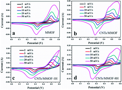 | ||
| Fig. 4 CV curves of MMOF (a), CNTs/MMOF (b), CNTs/MMOF-1H (c) and CNTs/MMOF-8H (d) electrodes at different scan rates. | ||
The same conclusion can be further confirmed by chronopotentiometry (CP) measurements as depicted in Fig. 5. Long discharge time represents high specific capacitance. Specifically, for CNTs/MMOF-8H electrode, the specific capacitance is calculated to be 804, 702, 646, 561, 506 and 469 F g−1 at current densities of 0.2, 0.5, 1.0, 2.0, 3.0 and 4.0 A g−1, respectively. The other detailed data are listed in Table S1.† The results indicate that CNTs additives, to different extent, improve the specific capacitances of MMOF, which are in keeping with the CV results. Notably, the maximum capacitance value can also be compared with that of recent reports on MOFs-based electrodes.6–8,11,16,17,30–33 These results suggest that introduction of CNTs not only influences the exterior morphology and thus further affects the surface area, the interface effect and synergy effect of the composite, but also indeed improves the resulting electrochemical performances through its morphology discrepancy.20,21
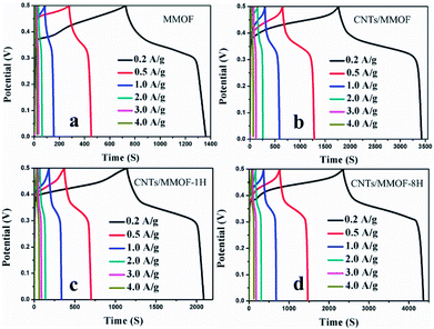 | ||
| Fig. 5 CP curves of MMOF (a), CNTs/MMOF (b), CNTs/MMOF-1H (c) and CNTs/MMOF-8H (d) electrodes at different current densities. | ||
After carefully checking from the table, the second discrepancy is generated, that is, the distinct rate capability. The detailed data show that 30.7%, 36.4%, 62.6% and 58.3% capacitance is maintained after 20 times (from 0.2 to 4.0 A g−1) increase for MMOF, CNTs/MMOF, CNTs/MMOF-1H and CNTs/MMOF-8H respectively (Fig. 6 and S2†). The result shows that CNTs exposed in external can maintain the stability of the hybrids, while the special structure, MMOF wrapped CNTs materials, enhances the rate capability but the level of enhancement is relatively low. The possible reason is that the exterior MMOF cannot protect the composites in electrochemical reaction process. Besides, the hydrothermal treatment, from SEM images, may improve the structural stability of MMOF itself than that of room-temperature synthesis.
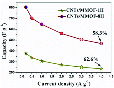 | ||
| Fig. 6 The specific capacitances of CNTs/MMOF-1H (star) and CNTs/MMOF-8H (circle) electrodes obtained from different current densities. | ||
The third difference originated from morphology discrepancy is embodied in coulombic efficiency. The coulombic efficiency (η/%) information can be calculated as η = td/tc × 100 (td and tc are the discharging and charging time respectively) from charge–discharge curves. The mean η is calculated to be 82.7%, 86.0%, 89.6% and 88.8% for MMOF, CNTs/MMOF, CNTs/MMOF-1H and CNTs/MMOF-8H electrode separately (Fig. 7). The result, the CNTs entangled with MMOF displaying better energy deliverable efficiency, is in good accordance with the conclusion from rate capability. It suggests that the possible reason of CNTs/MMOF-1H and CNTs/MMOF-8H displaying better rate capability and coulombic efficiency could be due to their stable structures after hydrothermal treatment. Notably, the affinity to faradaic reaction for entangled structure could be weaker than that of other CNTs/MMOF-based hybrids resulting in lower specific capacitance.
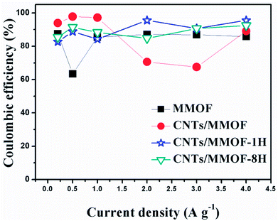 | ||
| Fig. 7 The coulombic efficiency of MMOF (cubic), CNTs/MMOF (circle), CNTs/MMOF-1H (star) and CNTs/MMOF-8H (triangle) electrodes obtained from different current densities. | ||
This conclusion can be proved by the electrical resistance data, which can be quantitatively documented by electrochemical impedance spectroscopy (EIS) measurements. The Nyquist plots for the as-synthesized MMOF and CNTs/MMOF-based electrodes conducted in the frequency range of 10 mHz to 100 kHz are depicted (Fig. 8). The plots for these electrodes are all consisted of one semicircle corresponded to redox reactions process. The absence of Warburg line suggests that the resistance caused by diffusion can be omitted and the overall electrochemical process is mainly dominated by kinetic control.34 An equivalent circuit is simulated according to the EIS data and depicted through ZView software in Fig. S3.† Rs (means series resistance) value can be obtained from the point intersecting with the Z′ axis at the high frequency region, while Rct (represents charge-transfer resistance) is determined from the diameter of semicircle. Based on the calculation and deduction, the Rs value for MMOF, CNTs/MMOF, CNTs/MMOF-1H and CNTs/MMOF-8H electrode is 0.43, 0.40, 0.64 and 0.57 Ω respectively, illustrating good wettability of MMOF even before compositing with CNTs. Correspondingly however, Rct value is determined to be 7.4, 2.9, 3.5 and 1.6 Ω. This result indicates that introduction of CNTs indeed enhance the conductivity of pristine MMOF and it can act as the conductive matrix, especially for the sample after eight hours of hydrothermal treatment, to support the MMOF to possess more fast charge transfer ability.
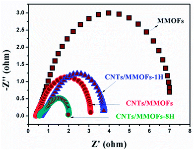 | ||
| Fig. 8 The Nyquist plots of MMOF, CNTs/MMOF, CNTs/MMOF-1H and CNTs/MMOF-8H electrodes obtained at room temperature. | ||
The last discrepancy caused by distinct morphology is the different cycling performance. The endurance tests using CV methodology at the same scan rate of 20 mV s−1 are presented as depicted in Fig. 9. After comparing the first cycle and 2000th continuous cycle, the capacitance retention maintains at 66.9%, 88.4%, 74.7% and 98.9% for MMOF, CNTs/MMOF, CNTs/MMOF-1H and CNTs/MMOF-8H electrode, respectively. This discrepancy phenomenon is basically in line with the above-mentioned results. Therefore, based on these results, CNTs serve as a good conductive matrix to enhance the conductivity, rate capability, coulombic efficiency and cycling life of MOF-based samples. Besides, alternation of preparing methods can change the final morphology of hybrids and thus result in discrepancy of performance.
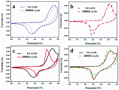 | ||
| Fig. 9 The endurance life of MMOF (a), CNTs/MMOF (b), CNTs/MMOF-1H (c) and CNTs/MMOF-8H (d) electrodes gained at a scan rate of 20 mV s−1. | ||
Conclusion
In summary, various CNTs/MMOF-based hybrids have been synthesized through compositing CNTs with Ni-triazole frameworks. The introduction of CNTs can alter the resulting morphology of the hybrids and consequently influence the electrochemical performance. The resulting performance discrepancies are specific capacitance, rata capability, coulombic efficiency and cycling endurance. The obtained CNTs/MMOF-based hybrids, especially for the CNTs/MMOF-8H structure, show a good rate capability after 20 times increase, a superior coulombic efficiency and an excellent long-term cycling stability (more than 98% retained after 2000 cycles). The distinct approaches for fabrication of various CNTs/MMOF hybrids should offer an effective methodology to enhance the rate capabilities of carbon-supported composite electrode materials in SCs fields.Conflicts of interest
There are no conflicts to declare.Acknowledgements
This work was supported by the Qing Lan Project of Jiangsu Province, the Natural Science Foundation of Jiangsu Province (BK20180514, BK20131314), the National Natural Science Foundation of China (21371098), the China Postdoctoral Science Foundation (2015M570430), the Jiangsu Postdoctoral Science Foundation (1401007C) and the Scientific Research Foundation of Nanjing Agricultural University (050804087).Notes and references
- O. M. Yaghi, M. O'Keeffe, N. W. Ockwig, H. K. Chae, M. Eddaoudi and J. Kim, Nature, 2003, 423, 705 CrossRef CAS PubMed.
- H. Furukawa, K. E. Cordova, M. O'Keeffe and O. M. Yaghi, Science, 2013, 341, 974 CrossRef CAS PubMed.
- M. Yaghi, G. Li and H. Li, Nature, 1995, 378, 703 CrossRef.
- Z. Liang, C. Qu, W. Guo, R. Zou and Q. Xu, Adv. Mater., 2018, 30, 1702891 CrossRef PubMed.
- X. Xu, J. Tang, H. Qian, S. Hou, Y. Bando, M. S. A. Hossain, L. Pan and Y. Yamauchi, ACS Appl. Mater. Interfaces, 2017, 9, 38737 CrossRef CAS PubMed.
- Y. Han, J. Li, T. Zhang, P. Qi, S. Li, X. Gao, J. Zhou, X. Feng and B. Wang, Chem. Eur J., 2018, 24, 1651 CrossRef CAS PubMed.
- H. Wang, M. Zhang, A. Zhang, F. Shen, X. Wang, S. Sun, Y. Chen and Y. Lan, ACS Appl. Mater. Interfaces, 2018, 10, 32265 CrossRef CAS PubMed.
- J. Yang, P. Xiong, C. Zheng, H. Qiu and M. Wei, J. Mater. Chem. A, 2014, 2, 16640 RSC.
- X. Liu, C. Shi, C. Zhai, M. Cheng, Q. Liu and G. Wang, ACS Appl. Mater. Interfaces, 2016, 8, 4585 CrossRef CAS PubMed.
- K. B. Wang, X. R. Cao, S. E. Wang, W. J. Zhao, J. Y. Xu, Z. K. Wang and H. Wu, ACS Appl. Mater. Interfaces, 2018, 10, 9104 CrossRef CAS PubMed.
- K. B. Wang, Z. K. Wang, X. Wang, X. Zhou, Y. Tao and H. Wu, J. Power Sources, 2018, 377, 44 CrossRef CAS.
- W. Yang, X. Li, Y. Li, R. Zhu and H. Pang, Adv. Mater., 2019, 31, 1804740 Search PubMed.
- Y. Q. Xue, S. S. Zheng, H. G. Xue and H. Pang, J. Mater. Chem. A, 2019, 7, 7301 RSC.
- M. H. Hassan, R. R. Haikal, T. Hashem, J. Rinck, F. Koeniger, P. Thissen, S. Heissler, C. Woll and M. H. Alkordi, ACS Appl. Mater. Interfaces, 2019, 11, 6442 CrossRef CAS PubMed.
- L. Li, R. Chen, Y. Gong, C. Yu, Z. Hui, H. Xu, X. Zhao, Y. Sun, W. Zhao and G. Sun, J. Mater. Chem. A, 2019, 7, 107 RSC.
- K. B. Wang, Z. K. Wang, S. E. Wang, Y. Chu, R. Xi, X. Zhang and H. Wu, Chem. Eng. J., 2019, 367, 239 CrossRef CAS.
- W. Zhou, P. Wang, C. Li, Q. Huang, J. Wang, Y. Zhu, L. Fu, Y. Chen and Y. Wu, RSC Adv., 2019, 9, 11253 RSC.
- Q. Yang, Y. Liu, M. Yan, Y. Lei and W. Shi, Chem. Eng. J., 2019, 370, 666 CrossRef CAS.
- Q. Zhang, Z. Zhou, Z. Pan, J. Sun, B. He, Q. Li, T. Zhang, J. Zhao, L. Tang and Z. Zhang, Adv. Sci., 2018, 5, 1801462 CrossRef PubMed.
- B. Brown, I. A. Cordova, C. B. Parker, B. R. Stoner and J. T. Glass, Chem. Mater., 2015, 27, 2430 CrossRef CAS.
- J. Zhang, S. Lu, Y. Xiang, P. K. Shen, J. Liu and S. P. Jiang, ChemSusChem, 2015, 8, 2956 CrossRef CAS PubMed.
- Y. F. Wang, S. X. Zhao, L. Yu, X. X. Zheng, Q. L. Wu and G. Z. Cao, J. Mater. Chem. A, 2019, 7, 7406 RSC.
- B. Li, Z. Tian, H. Li, Z. Yang, Y. Wang and X. Wang, Electrochim. Acta, 2019, 314, 32 CrossRef CAS.
- N. Sheng, S. Chen, J. Yao, F. Guan, M. Zhang, B. Wang, Z. Wu, P. Ji and H. Wang, Chem. Eng. J., 2019, 368, 1022 CrossRef CAS.
- Z. Shi, L. Yue, X. Wang, X. Lei, T. Sun, Q. Li, H. Guo and W. Yang, J. Alloys Compd., 2019, 791, 665 CrossRef CAS.
- H. Zhou and G. Han, Electrochim. Acta, 2016, 192, 448 CrossRef CAS.
- D. Sherbla, J. C. Bachman, J. S. Elias, C. J. Sun, Y. Shao-Horn and M. Dincă, Nat. Mater., 2017, 16, 220 CrossRef PubMed.
- W. Zhao, J. Peng, W. Wang, B. Jin, T. Chen, S. Liu, Q. Zhao and W. Huang, Small, 2019, 15, e1901351 CrossRef PubMed.
- F. H. Allen, The Cambridge Structural Database: a quarter of a million crystal structures and rising, Acta Crystallogr. Sect. B Struct. Sci, 2002, 58, 380 CrossRef PubMed.
- L. J. Bellamy, The Infrared Spectra of Complex Molecules, Wiley, New York, 1958 Search PubMed.
- Y. Y. Kannangara, U. A. Rathnayake and J. K. Song, Chem. Eng. J., 2019, 361, 1235 CrossRef CAS.
- A. K. Diaz-Duran, G. Montiel, F. A. Viva and F. Roncaroli, Electrochim. Acta, 2019, 299, 987 CrossRef CAS.
- R. Rajak, M. Saraf and S. M. Mobin, J. Mater. Chem. A, 2019, 7, 1725 RSC.
- P. Simon, Y. Gogotsi and B. Dunn, Science, 2014, 343, 1210 CrossRef CAS PubMed.
Footnote |
| † Electronic supplementary information (ESI) available: The rate capability of MMOF and CNTs/MMOF and Table S1. See DOI: 10.1039/c9ra05442a |
| This journal is © The Royal Society of Chemistry 2019 |

