 Open Access Article
Preparation and 3D-printing of highly conductive polylactic acid/carbon nanotube nanocomposites via local enrichment strategy†
Shaohong Shi,
Yinghong Chen *,
Jingjing Jing and
Lu Yang
State Key Laboratory of Polymer Materials Engineering, Polymer Research Institute of Sichuan University, Chengdu 610065, China. E-mail: johnchen@scu.edu.cn
First published on 23rd September 2019
Abstract
In this paper, a local enrichment strategy was adopted to prepare carbon nanotube (CNT) enriched polylactic acid (PLA) composite filaments, which were used to fabricate the corresponding conductive 3D-printed parts by fused deposition modeling (FDM) technology. Combined with computer simulation, the carbon nanotubes (CNTs) were found to be successfully kept and supported on the surface of filaments after 3D-printing. With this strategy, the prepared 3D-printed parts showed a remarkably enhanced electrical conductivity, which was approximately eight orders of magnitude higher than that of the conventional 3D-printed parts at the same loading of CNTs. This encouraging result provided a new method for fabricating the high-performance parts through FDM printing, and also opened up new routes for 3D-printing technologies to prepare other advanced binary or multicomponent polymer composites.
Introduction
In recent years, there has been increasing interest focusing on the preparation of multifunctional parts by using 3D-printing (also known as additive manufacturing) technologies due to their immensely potential applications in various areas such as aerospace, medicine and electronics.1–4 The 3D-printing technologies are fundamentally different from the conventional processing and molding technologies, because they utilize a ‘layer by layer stacking’ approach rather than integral manufacturing to fabricate the parts. The advantages in 3D-printing technologies could be that they can fabricate a series of desired parts with complex geometries and personalized characteristics. These advantages can impart a great application potentiality to this technology in the manufacturing field in the future.5–7 However, the deficiencies in raw materials, especially multifunctional materials, which are suitable for 3D-printing, restrict the development of this technology to a great extent.8,9Generally, the multifunctional polymer composites consist of a polymer matrix and functional fillers. Carbon based fillers including graphene, carbon nanotubes (CNTs) and carbon fiber (CF) are commonly used as the second component to satisfy the demands of polymer materials for the functionality.10–14 For the conventional functional composites, such as conductive polymer nanocomposites (CPNs), the construction of conductive networks is mainly depended on the traditional percolation theory, which is due to the formation of long-range filler's connectivity in random systems.15–17 While above the percolation threshold, a giant connected network could be formed. In order to achieve this connectivity in random systems, a high loading of fillers is generally required. This would not only result in waste of materials, but also lead to the deterioration in processability of composites. The extrusion based additive manufacturing, also known as fused deposition modeling (FDM) or fused filament fabrication (FFF), is one of the commonly used 3D-printing technologies.18 A good processability is a basic guarantee for the successful manufacturing.19,20 Therefore, how to coordinate the loading of filler and the processability of material has become an urgent issue to be solved.
It is well known that the properties of one material not only depend on the content of functional fillers but also are influenced by the distribution of filler in matrix. The selective distribution of fillers would impart an excellent functional property to the composites with lower filler loading.21–23 Typically, the construction of segregated structures, which is done by incorporating a small amount of highly conductive nanoparticles in a polymer matrix, could fabricate the composites with improved electrical conductivity over traditionally randomly distributed composites.24–26 In order to achieve above purpose, our group has also utilized simple but effective strategies to realize the preparation of high-performance materials with lower filler loading.27–30 By using solution dispersion and physical deposition, the fillers were selectively coated on the surface of polyamide 11 (PA11) particles. Then, the coated PA11 particles were used for selective laser sintering (SLS), which was also one of the important 3D-printing technologies. Finally, a filler network was found to be successfully constructed in polymer matrix. The sintered parts exhibited an excellent electrical property.29 Because there is very weak shear field in sintering process and the polymer particles coated with the functional fillers can be directly melted and printed under the irradiation of laser, it is easy to tailor the filler distribution and maintain the filler network at the interface between layers of parts. However, compared with selective laser sintering technology, for FDM technology, it is very difficult to effectively keep the filler network structure whether in preparation of the filaments or in processing of the parts. The filler network is very easily destroyed by stronger shear flow field in melt processing. In recent years, the great success in the precise manipulation and construction of the filler network is still deficient in FDM 3D-printing technology.31,32 Typically, Green et al.32 used a standard desktop FDM printer to achieve the selective distribution of CNT-enriched layer at the interface of parts, which is sensitive to radio frequency. The intense localized heating of carbon nanotubes (CNTs) under microwave irradiation would greatly strengthen the interfacial welding of filaments, finally resulting in a 275% improvement of the weld fracture strength of 3D-printed parts. This remarkable result opens up entirely new design spaces for FDM 3D-printing. However, the distribution mechanism of fillers and the functionality were not involved. Whether the 3D-printed parts have the functionality needs to be further investigated and developed.
In this paper, for the first time we proposed a novel “local enrichment strategy (LES)” to successfully achieve the construction of filler network at the interface of polylactic acid (PLA)/carbon nanotubes (CNTs) nanocomposite filaments at a low CNTs loading used in FDM printing technology. Firstly, we used computer numerical simulation to predict the filler movement paths in FDM printing. The simulation results showed that when the printing conditions were delicately controlled, the distribution of filler particles coated on the surface of filaments would not change during FDM printing process, which provided a theoretical basis for our local enrichment strategy. We adopted above idea to realize the direct enrichment of CNTs on the surface of PLA filaments. The CNTs enriched filaments were then used to prepare the 3D-printed parts using FDM printer. Compared with the conventional 3D-printed parts, where the used filaments were prepared through simply melt-compounding in twin screw extruder at the same material composition, the current 3D-printed parts, where the used filaments were prepared through local enrichment strategy, showed a dramatical improvement in electrical conductivity, which was approximately eight orders of magnitude higher than that of the conventional parts (the detailed descriptions and measurements were provided in the ESI†). Obviously, above encouraging result showed that our local enrichment strategy has a very promising future. It provided a new idea to fabricate the high-performance binary or multicomponent polymer composites through 3D-printing technologies.
Results and discussion
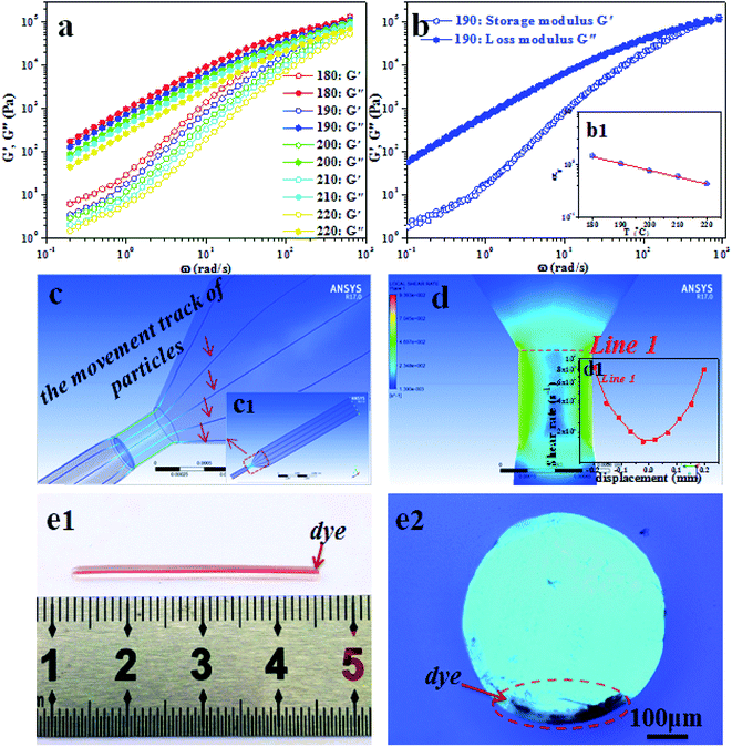
In order to carry out the local enrichment strategy during FDM printing, simulation was used to investigate whether the fillers could be still located at the interface of filaments after FDM printing. First of all, the intrinsic parameters of PLA used for simulation, including zero shear viscosity, relaxation time, shift factor and power law index, were obtained by combining with the rheological measurements. Fig. 1a and b presented the frequency sweeping curves, the corresponding time–temperature shift master curve of PLA (reference temperature 190 °C) and the shift factor αT of PLA for generating master curve. In Fig. 1a, a typical characteristic of homopolymer-like terminal flow behavior was exhibited.33,34 For the G′ and G′′ at different temperature, the variation tendency of their viscoelastic responses was similar and all increased monotonically with the frequency increasing. In addition, both G′ and G′′ showed the decreasing tendency with the temperature increasing. In order to obtain the rheological parameters more accurately, a time–temperature shift (TTS) was conducted for all frequency sweeping curves. The TTS master curve (reference temperature 190 °C) and the shift factor were shown in Fig. 1b. Here, the rheological parameters of PLA were fitted by Carreau–Yasuda model.35 Combining these rheological parameters and the geometry of FDM printing liquefier channel, the obtained simulation results were shown in Fig. 1c and d (the detailed description of the simulation was provided in the ESI†). In Fig. 1c-c1, the movement paths of labeled particles were represented by the blue curves. The obtained smooth curves revealed that the melting flow in whole liquefier channel was steady. This result was also verified by the shear rate distribution shown in Fig. 1d and the inset of the shear rate curve along the radial direction (Fig. 1d1). It was clearly observed that there was a small shear fluctuation in the shear rate range from 102 s−1 to 103 s−1. These typical characteristics implied that a “streamline flow” existed in the whole liquefier channel and there is no obvious “turbulent flow” phenomenon occurring in the convergence region. This flow pattern indicated that the fluids of either polymer melt or filler were steady through the liquefier channel during the whole processing. Hence, we could preliminarily believe that the filler particles coated on the filament surface could basically maintain at its original state by delicately controlling the printing conditions.Subsequently, a tracing experiment using dyes as the tracer was conducted to verify above simulation results. The experimental results of filaments before and after printing were shown in Fig. 1e1 and e2. As we expected, the location of dyes marked on the surface of filaments did not change after printing. This experimental result further verified that the filler particles could be effectively kept on the surface of filaments after printing.
As discussed above, the numerical simulation laid the theoretical basis for successfully implementing the local enrichment strategy. It was also essential to support the fillers on the surface of filaments before printing. For this purpose, we adopted a simple support method. Firstly, the CNTs were dispersed in a polycaprolactone solution using dichloromethane as the solvent at a certain concentration. Then, the pure PLA filaments were coated with CNTs particles by going through the prepared CNTs contained polycaprolactone solution at a constant drawing speed. The constant drawing speed ensured the uniform deposition of CNTs particles on the PLA filament surface. In whole processing, the introduced polycaprolactone played an adhesive role in controlling the solution viscosity and made it possible to realize the physical deposition of CNTs. Fig. 2a, b and b1 showed the SEM results of filament surface before and after CNTs deposition. Clearly, after treatment, the smooth surface became very rough. Particularly, in the SEM image with higher magnification (Fig. 2b1), the aggregates of CNTs were clearly observed on the filament surface. In order to investigate the quality of adhesion between CNTs and PLA, SEM was used to carefully observe the corresponding fractured surface of filaments (Fig. 2c–c3). In Fig. 2c1, clearly, a thin CNTs layer with about ∼25 μm thickness adhered tightly to the surface of filament, and at high magnification (Fig. 2c2), numerous rod-like CNTs are found to be embedded in the PLA matrix. These phenomena indicated that the adhesion between CNTs and PLA might be strong. On the contrary, in the inner region (Fig. 2c3), it was smooth and flat. This obvious difference showed that the CNTs were successfully enriched on the surface of filaments after CNTs deposition. FT-IR measurement was also tried to investigate the possible interaction between the enriched CNTs and PLA matrix (see the ESI†). The results showed that there were almost no changes in the characteristic absorptions of PLA before and after introduction of CNTs. This indicated that there was possibly no chemical interaction, e.g. grafting reaction, occurring between CNTs and PLA.
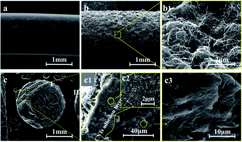 | ||
| Fig. 2 SEM micrographs of the filament surface before (a) and after (b and b1) CNTs deposition; the corresponding fractured surface of the filament after deposition (c–c3). | ||
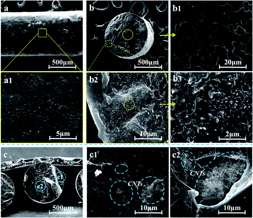
The preliminary experimental results showed that the CNTs coated filaments had been successfully prepared through the local enrichment strategy. However, in order to make it clear whether this structure can be effectively kept on the surface of filaments after FDM printing, more investigations need to be conducted. Here, we used the same printing conditions as mentioned before. A single filament was firstly used to print the parts so as to investigate the microstructure of filament after printing. The SEM results were shown in Fig. 3a and a1. Compared with the SEM results before FDM printing, the rough surface of filaments became smoother, except that a few of impurities were randomly distributed on the filament surface, which were possibly attributed to the adhesive of polycaprolactone. Obviously, during this printing process, the reconstruction possibly took place on the surface of PLA filaments coated with CNTs layer due to an effective melting in the liquefier channel, resulting in a smooth surface of PLA filament after printing. However, based on our strategy, the strong interaction and diffusion between PLA matrix and CNTs was not beneficial to the support of CNTs in local enrichment structures. For studying the structures of filament, the fractured surface was further observed and the results were shown in Fig. 3b–b3. Fortunately, it was found that the desired CNT-enriched structures were successfully kept on the surface of PLA filament. In the higher-magnification field of view, it was clearly observed that the numerous dot-like CNTs were located in the outer region (Fig. 3b3), but in the inner region (Fig. 3b1) the fractured surface was still smooth and flat, which was in accordance with the previous results before printing (Fig. 2c–c3). The reference R-PLA/CNTs material with the same composition was prepared by the conventional melt-compounding method. The FDM printed reference filament was further observed by SEM. The results showed that on the fractured surface of filament, there was the distribution of CNTs in either the outer region or the inner region (Fig. 3c–c2). This difference between two methods proved that the local enrichment structures were successfully obtained on the surface of filaments by controlling the printing conditions with assistance of simulation. In order to clearly illustrate the local enrichment strategy, a schematic diagram was shown in Fig. 4, which clearly explained how to conduct the deposition of CNTs on the surface of filament and how to form the local enrichment structures on or nearby the surface of filament.
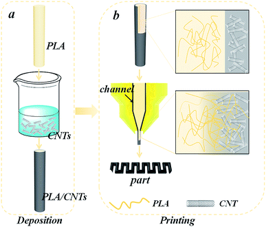 | ||
| Fig. 4 Schematic diagram of the local enrichment strategy for deposition (a) and printing (b) processing. | ||
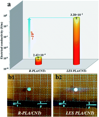
An effort was made to have a comprehensive understanding of the construction of the local enrichment structures. However, whether such a structure can exhibit the excellent property we expected was still not clear. So, a LES PLA/CNTs circular part with a diameter of 12 mm and a thickness of 2 mm from LES materials was prepared by FDM 3D-printing technology under the same condition as stated before. For purpose of comparison, the reference R-PLA/CNTs circular part from the melt-compounding materials with the same composition was also prepared under the same FDM 3D-printing conditions. The electrical conductivities of above two FDM 3D-printed parts were shown in Fig. 5a. As can be seen, compared with the electrical conductivity of conventional R-PLA/CNTs FDM part (2.42 × 10⁻⁹ S m−1), the one of LES PLA/CNTs FDM part dramatically increased to 3.28 × 10⁻¹ S m−1, showing an increase by eight orders of magnitude. This remarkable enhancement implied that the PLA/CNTs FDM part experienced a transformation from the insulator (conventional part) to the conductor (LES part) by adopting the local enrichment strategy. Obviously, the construction of filler networks in FDM 3D-printed part played a crucial role in improving the electrical conductivity. The local enrichment strategy we proposed was successfully used to make the CNTs aggregates selectively distributed on or nearby the filaments surface before and after FDM printing. During the “layer-by-layer stacking” 3D-printing process, the surfaces of filament melts coming out of nozzle would be bonded with the surfaces of the old solidified ones below, and thus the CNT networks could be effectively built between interface of filaments during FDM printing. As a result, the conductive functional parts with high conductivity could be successfully fabricated at a low CNTs loading. However, for the conventional R-PLA/CNTs sample, it was difficult to construct the conductive network through the connectivity between filler particles, since in the random system the content of CNTs was lower than the percolation threshold. For more intuitive comparison, a simple direct-current circuit was constructed by using the conventional R-PLA/CNTs FDM wave-like part and the LES PLA/CNTs FDM wave-like part as the conductive connection, respectively (both FDM parts were not made from one single filament but from the layer-by-layer stacking of filaments during FDM printing). As shown in Fig. 5b, when the LES PLA/CNTs FDM wave-like part was connected with both ends of the circuit, the LED light was on. This indicated that a conductive path was successfully formed and the LES PLA/CNTs FDM wave-like part had a very good electrical conductivity. It should be noticed that the layer-by-layer adhesion would possibly lead to the anisotropism in conductivity of the 3D-printed parts to a certain degree. The conductivity of the 3D-printed parts is at the best along the melt flow direction during FDM printing. That is to say, the layer-by-layer adhesion may have an effect on conductivity due to the contact resistance. This is interesting and remains the further investigation later. Comparatively, when the conventional R-PLA/CNTs FDM wave-like part was connected with both ends of the circuit, the light was off. This meant that the conventional R-PLA/CNTs FDM wave-like part had the high electrical resistance (poor electrical conductivity) which impeded the directional movement of electrons. Above comparison showed that the highly conductive functional FDM 3D-printed part could be really fabricated by using the local enrichment strategy.
Conclusion
In conclusion, a novel local enrichment strategy was adopted to fabricate the conductive PLA/CNTs FDM 3D-printed parts. Combining the numerical simulation and the experimental design, the conductive filler network was successfully constructed by locally enriching the CNTs on the surface of PLA filament. Compared with the FDM 3D-printed part of the conventional R-PLA/CNTs composite filaments, the corresponding FDM 3D-printed part of the PLA/CNTs composite filaments prepared through local enrichment strategy had the substantially enhanced electrical conductivity, which was eight orders of magnitude higher than that of the former. This made it possible for PLA/CNTs composite with the same composition to dramatically transform from insulator to conductor. The encouraging results occurring in preparation of multifunctional polylactic acid composite 3D-printed parts also provided a new idea for fabrication of the other high-performance functional composite parts through FDM 3D-printing.Conflicts of interest
There are no conflicts to declare.Acknowledgements
This work is financially supported by the National Key R&D Program of China (2017YFE0111500), the National Natural Science Foundation of China (51433006), the European Union’s Horizon 2020-MSCA-RISE-734164 Graphene 3D Project, the Program of Innovative Research Team for Young Scientists of Sichuan Province (2016TD0010) and the Fundamental Research Funds for the Central Universities.References
- F. P. W. Melchels, M. A. N. Domingos, T. J. Klein, J. Malda, P. J. Bartolo and D. W. Hutmacher, Prog. Polym. Sci., 2012, 37(8), 1079–1104 CrossRef CAS.
- K. Chizari, M. A. Daoud, A. R. Ravindran and D. Therriault, Small, 2016, 12(44), 6076–6082 CrossRef CAS PubMed.
- S. Z. Guo, K. Qiu, F. Meng, S. H. Park and M. C. McAlpine, Adv. Mater., 2017, 29(27), 1701218 CrossRef PubMed.
- M. Sireesha, J. Lee, A. S. Kranthi Kiran, V. J. Babu, B. B. T. Kee and S. Ramakrishna, RSC Adv., 2018, 8, 22460–22468 RSC.
- T. D. Ngo, A. Kashani, G. Imbalzano, K. T. Q. Nguyen and D. Hui, Composites, Part B, 2018, 143, 172–196 CrossRef CAS.
- S. A. M. Tofail, E. P. Koumoulos, A. Bandyopadhyay, S. Bose, L. O'Donoghue and C. Charitidis, Mater. Today, 2018, 21(1), 22–37 CrossRef.
- X. Wang, M. Jiang, Z. Zhou, J. Gou and D. Hui, Composites, Part B, 2017, 110, 442–458 CrossRef CAS.
- S. Kumar and J. P. Kruth, Mater. Des., 2010, 31, 850–856 CrossRef CAS.
- U. Kalsoom, P. N. Nesterenko and B. Paull, RSC Adv., 2016, 6, 60355–60371 RSC.
- H. Wei, X. Cauchy, I. O. Navas, Y. Abderrafai, K. Chizari, U. Sundararaj, Y. Liu, J. Leng and D. Therriault, ACS Appl. Mater. Interfaces, 2019, 11, 24523–24532 CrossRef CAS PubMed.
- K. Fu, Y. Yao, J. Dai and L. Hu, Adv. Mater., 2017, 29(9), 1603486 CrossRef PubMed.
- Z. C. Kennedy, J. F. Christ, K. A. Evans, B. W. Arey, L. E. Sweet, M. G. Warner, R. L. Eriksonb and C. A. Barrett, Nanoscale, 2017, 9(17), 5458–5466 RSC.
- C. L. Manzanares Palenzuela, F. Novotny, P. Krupicka, Z. Sofer and M. Pumera, Anal. Chem., 2018, 90(9), 5753–5757 CrossRef CAS PubMed.
- K. Chizari, M. Arjmand, Z. Liu, U. Sundararaj and D. Therriault, Mater. Today Commun., 2017, 11, 112–118 CrossRef CAS.
- L. Chen, X. J. Pang and Z. L. Yu, Mater. Sci. Eng., A, 2007, 457, 287–291 CrossRef.
- J. E. F. Fangming Du and K. I. Winey, J. Polym. Sci., Part B: Polym. Phys., 2003, 41, 3333 CrossRef.
- M. Arjmand, T. Apperley, M. Okoniewski and U. Sundararaj, Carbon, 2012, 50, 5126–5134 CrossRef CAS.
- S. H. Masood, Rapid Prototyp. J., 1996, 2, 24–33 CrossRef.
- G. Chen, N. Chen and Q. Wang, Mater. Des., 2018, 157, 273–283 CrossRef CAS.
- Q. Sun, G. M. Rizvi, C. T. Bellehumeur and P. Gu, Rapid Prototyp. J., 2008, 14(2), 72–80 CrossRef.
- A. Goldel, G. Kasaliwal and P. Potschke, Macromol. Rapid Commun., 2009, 30, 423–429 CrossRef PubMed.
- J. Chen, Y. Y. Shi, J. H. Yang, N. Zhang, T. Huang, C. Chen, Y. Wang and Z. W. Zhou, J. Mater. Chem., 2012, 22, 22398 RSC.
- D. X. Yan, H. Pang, B. Li, R. Vajtai, L. Xu, P. G. Ren, J. H. Wang and Z. M. Li, Adv. Funct. Mater., 2015, 25, 559–566 CrossRef CAS.
- S. Yuan, J. Bai, C. K. Chua, J. Wei and K. Zhou, Composites, Part A, 2016, 90, 699–710 CrossRef CAS.
- J. Du, L. Zhao, Y. Zeng, L. Zhang, F. Li, P. Liu and C. Liu, Carbon, 2011, 49, 1094–1100 CrossRef CAS.
- C. H. Cui, H. Pang, D. X. Yan, L. C. Jia, X. Jiang, J. Lei and Z. M. Li, RSC Adv., 2015, 5, 61318–61323 RSC.
- F. Qi, N. Chen and Q. Wang, Mater. Des., 2017, 131, 135–143 CrossRef CAS.
- Z. Li, Z. Wang, X. Gan, D. Fu, G. Fei and H. Xia, Macromol. Mater. Eng., 2017, 302, 1700211 CrossRef.
- F. Qi, N. Chen and Q. Wang, Mater. Des., 2018, 143, 72–80 CrossRef CAS.
- X. Gan, J. Wang, Z. Wang, Z. Zheng, M. Lavorgna, A. Ronca, G. Fei and H. Xia, Mater. Des., 2019, 178, 107874 CrossRef CAS.
- H. Kim, F. Torres, M. T. Islam, M. D. Islam, L. A. Chavez, C. A. Garcia Rosales, B. R. Wilburn, C. M. Stewart, J. C. Noveron, T. L. B. Tseng and Y. Lin, MRS Commun., 2017, 7, 960–966 CrossRef CAS.
- C. B. Sweeney, B. A. Lackey, M. J. Pospisil, T. C. Achee, V. K. Hicks, A. G. Moran, B. R. Teipel, M. A. Saed and M. J. Green, Sci. Adv., 2017, 3, 6 Search PubMed.
- R. C. S. Fangming Du, W. Zhou, S. Brand, J. E. Fischer and K. I. Winey, Macromolecules, 2004, 37, 9048–9055 CrossRef.
- Y. Song and Q. Zheng, Polymer, 2010, 51, 3262–3268 CrossRef CAS.
- M. Ebrahimi, V. K. Konaganti, S. Moradi, A. K. Doufas and S. G. Hatzikiriakos, Soft Matter, 2016, 12, 9759–9768 RSC.
Footnote |
| † Electronic supplementary information (ESI) available. See DOI: 10.1039/c9ra05684j |
| This journal is © The Royal Society of Chemistry 2019 |

