 Open Access Article
Dynamic interplay of alkali cations and a natural organic binder in the microstructural evolution of Cu2ZnSnS4 thin films prepared from Cu2ZnSnS4 powder-containing inks
Anies Mutiari *abc,
Neha Bansala,
Raad Hamidd,
Martin Artnere,
Veronika Mayerf,
Juergen Rothf,
Matthias Weil
 b and
Rachmat Adhi Wibowo*a
aAIT Austrian Institute of Technology GmbH, Center for Energy, Photovoltaic Systems, Giefinggasse 2, 1210 Vienna, Austria. E-mail: anies.mutiari@ait.ac.at; Rachmat.wibowo@ait.ac.at; Fax: +43 50550-6311; Tel: +43 50550-6384
bInstitute for Chemical Technologies and Analytics, Technical University of Vienna, Getreidemarkt 9/164-SC, 1060 Vienna, Austria
cCenter for Materials and Technical Products, Ministry of Industry Republic of Indonesia, Jl. Sangkuriang 14, Bandung 40135, Indonesia
dAIT Austrian Institute of Technology GmbH, Center for Low Emission Transport, Electric Drives Technilogies, Giefinggasse 2, 1210 Vienna, Austria
eFrimeco Produktions GmbH, Aspernbruekenstrasse 2, 1020 Vienna, Austria
fPMT Jetmills GmbH, Industriepark 1, 8773 Kammern im Liesingtal, Austria
First published on 11th September 2019
Abstract
The use of pre-synthesised Cu2ZnSnS4 (CZTS) sub-micron powders as a raw material for preparing CZTS thin films for photovoltaic absorber applications is examined. A challenge in preparing photovoltaic device-relevant CZTS films from submicron powders is producing a dense CZTS film by a sintering process. This is due to the nature of non-unimodal particle size and morphology that typically lead to the formation of pores after sintering. This work aimed to study the sintering behaviour of CZTS films that were prepared from a CZTS powder-containing ink. Complementary DT-TGA and in situ X-ray powder diffraction studies at elevated temperature reveal that the tetragonal kesterite phase in the as-sintered CZTS film is stable until 620 °C. An effective tendency of CZTS powder towards film recrystallisation occurs when alkali cations (Na and/or K) are added to the ink. For the first time, effects of additional natural gum as a binder in the CZTS powder-containing ink on the CZTS film sintering behaviour were also investigated. Contrary to the positive effects of alkali addition, the binder inhibits recrystallisation of CZTS. Therefore, the amount of binder was controlled in a quantity large enough to modify the ink viscosity, but low enough to allow large CZTS grain growth during sintering. A dense and compact as-sintered CZTS film can be produced from a CZTS powder-containing ink with 10 mol% Na and 2 mol% K alkali addition along with 3 wt% binder addition.
Introduction
Cu2ZnSnS4 (CZTS, mineral name kesterite) is a promising and emerging absorber material for thin film photovoltaic applications due to its optoelectronic properties. CZTS also contains abundant elements, which potentially secures the terra Watt-scale CZTS photovoltaic deployment scenario.1,2 Currently, the efficiency record for CZTSSe has reached 12.6%,3 and over 10% for CZTS.4 In the past few years, the solution-based process has been demonstrating high-throughput and cost-effective CZTS thin film absorber fabrication.5 This process can be divided into nanoparticle-based and molecular-based routes.6 Both routes have been used to deposit a precursor film on a Mo-coated glass substrate subjected to subsequent chalcogenization at 550–620 °C. The challenge facing solution-based processing is its limitation to grow a dense CZTS film with large grain sizes.1 Moreover, a solution-based processed CZTS film typically produces a bi-layer structure with two distinct grain sizes due to the effect of residual carbon originating from the organic solvent.7,8 This bi-layer film structure has a lower performance compared to the single layer microstructure of the champion CZTS device.3An alternative CZTS film solution processing under avoidance of the bi-layer structure can utilize a dispersion of sub-micron pre-synthesized CZTS powders in a liquid solvent. The dispersion or ink is coated on a substrate to produce a CZTS layer that is subsequently heated to form a dense CZTS layer. The use of CZTS pre-synthesised powder as an ink component is beneficial because pre-synthesized CZTS powder can be produced through an industrial-scale processing, such as pyrometallurgy.9
The densification of CZTS films from a CZTS powder-containing ink requires thermal treatment for triggering CZTS powder fusion and subsequent crystal growth (recrystallisation), namely thin film sintering.5 Typically, the sintering process is performed at a temperature just below the material's melting point. This means that sintering of a CZTS film from pre-synthesized powder should be carried out at about 800 °C (CZTS melts at 990 °C). However, this temperature is definitely above the glass substrate softening point (i.e. about 640 °C).
Several methods can be used to reduce sintering temperatures, including addition of a fluxing agent.10–12 A fluxing agent leads to flow type behaviour at low temperature sintering,8 and thus accelerates the powder to sinter more effectively at lower temperatures. Potential fluxing agents are salts of alkali metals Na, Li, K, Rb and Cs.13 All aforementioned flux agents may also be used to enhance the crystallinity of CZTS films prepared from CZTS powder-containing inks.
This contribution sums up the effects of thermal processing on the densification of CZTS films prepared from CZTS powder-containing inks at a temperature below the glass softening point. It is shown that the densification and recrystallisation or sintering of CZTS films can take place in the presence of alkali addition. Furthermore, the optimization of ink formulation by controlling the natural binder content along with its influences on CZTS films properties are also discussed.
Experimental details
CZTS powder with a particle size of ∼50 μm and chemical composition of Cu/(Zn + Sn) = 0.78 and Zn/Sn = 1.12 was received from Frimeco Produktions GmbH, Austria. As a much smaller particle size is required for CZTS thin film preparation, the size was further reduced by employing jet milling (PMT Spiral Jetmill CSJ3-CR250 at PMT Powder Processing GmbH, Austria). Determination of particle size distribution for evaluating the CZTS particle size before and after milling was done by using a laser particle size analyser (Lasergranulometer Cilas 1064L with wet dispersion in water).The CZTS powder-containing ink formulation was initiated by firstly establishing an original ink recipe. 25 grams of as-milled CZTS powder and a natural binder 0.75 grams of gum arabic (GA) from acacia tree (Sigma Aldrich, Austria) were firstly dispersed in 14 mL of de-ionized water. Subsequently, sodium acetate trihydrate (99.0% purity, Sigma-Aldrich Austria) and potassium carbonate (99.0% purity, Sigma-Aldrich Austria) were added as alkali sources into the original CZTS ink formulation with alkali![[thin space (1/6-em)]](https://www.rsc.org/images/entities/char_2009.gif) :
:![[thin space (1/6-em)]](https://www.rsc.org/images/entities/char_2009.gif) CZTS molar ratios varied from 0 to 10 mol%. Furthermore, the optimization of ink was done by varying GA relative to the CZTS powder weight from 0 to 6 wt%. Throughout this study, all inks were ultrasonicated (Hielscher UP200St, Germany) for four minutes. The viscosity of the resulting CZTS inks were measured at various shear rates using a viscometer (Brookfield DV1 Digital Viscometer, Germany).
CZTS molar ratios varied from 0 to 10 mol%. Furthermore, the optimization of ink was done by varying GA relative to the CZTS powder weight from 0 to 6 wt%. Throughout this study, all inks were ultrasonicated (Hielscher UP200St, Germany) for four minutes. The viscosity of the resulting CZTS inks were measured at various shear rates using a viscometer (Brookfield DV1 Digital Viscometer, Germany).
CZTS films from the CZTS inks were deposited on 2.5 × 2.5 cm2 Mo-coated glass substrates by spin coating (Spin Coater, Osilla, UK) at 1500 rpm for one minute followed by air-annealing at 300 °C for another minute. The as-coated CZTS film was placed into a graphite container together with excessive sulfur flakes (99.99% purity, Sigma-Aldrich Austria). Subsequently, the graphite container was brought inside a silica tube furnace where the sintering process of CZTS films took place. The silica tube was firstly evacuated with a vacuum pump prior to nitrogen purge for minimizing oxygen residue. During sintering of CZTS films, the atmosphere was kept at 1 atm through continuous flowing of 200 sccm N2. The tube was heated from room temperature to 620 °C at 10 °C min−1 heating rate. The sintering process was performed at this temperature for two hours. Afterwards the furnace was cooled naturally to room temperature.
The morphological properties of CZTS powders and films were investigated by electron microscopy (SEM Carl Zeiss Supra 40, Germany) for film surface and cross-sectional observations as well as by X-ray powder diffraction (XRPD; Equinox 100 ThermoFischer, Switzerland) for phase and crystallographic analysis.
The molar ratio of metals within the CZTS absorber films was determined by inductively coupled plasma (ICP) analysis on a Thermo Fischer iCAP Q (Bremen, Germany) coupled with a quadrupole mass detector. For this measurement, the thin film samples were immersed in aqua regia to dissolve all components. X-ray powder diffraction measurements of the films were carried out on a PANalytical X'Pert Pro diffractometer in grazing incident geometry using a mirror for separating Cu Kα1,2 radiation and an X'Celerator linear detector. For the in situ temperature-dependent monitoring of experiments, an Anton Paar HTH1200N chamber was used. Thermal analysis of CZTS powder prior to sintering was also performed by using differential thermogravimetry (DT-TGA, NETZSCH-Gerätebau GmbH, Germany) from room temperature to 1000 °C at a heating rate of 10 °C min−1 under Ar atmosphere in order to simulate CZTS thermal behavior during sintering. Finally, to investigate the structural properties of as-deposited and as-sintered CZTS films, Raman spectroscopy (LabRAM HR Horiba, Jobin-Yvon) at an excitation wavelength of 532 nm was employed.
Results and discussion
Powder properties
The as-received CZTS powder initially exhibited a non-unimodal size distribution with particle sizes ranging between 30–50 μm for most of the particles (Fig. 1, top). This range of particle size is definitely not suitable for preparing a thin film absorber with a typical thickness of only 2–3 μm. Subsequent jet milling significantly reduced the CZTS particle size accompanied with a narrower distribution (Fig. 1, bottom). Jet milling is much more superior than other reported milling techniques14 to produce particles to a sub-micron size as well as to produce sharp particle distribution. D50 – the median value of the milled CZTS powder – is 0.65 μm and thus suitable for preparing a CZTS thin film absorber.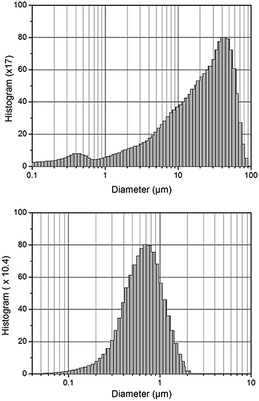 | ||
| Fig. 1 CZTS particle size distribution of the as-received powder (top) and after jet milling (bottom). | ||
In situ analysis of milled CZTS powder with DT-TGA and XRPD
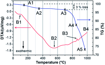
Thermal analysis of sub-micron CZTS powder illustrates a set of endothermic–exothermic reactions and mass changes at elevated temperatures (Fig. 2), simulating the sintering process. The mass loss of about 3% during heating from 100 to 300 °C (A1–A3) is most likely caused by evaporation of sulfur from the bulk of CZTS powder. This process starts together with the first detected endothermic reaction (B1) at about 100–110 °C which indicates the melting of sulfur. Above 300 °C, the mass of CZTS powder tends to be stable (A2–A3) whereas the DTA signal gradually decreases until it reaches a minimum at 570–580 °C, represented as point B2. This gradual decrease represents a sluggish exothermic decomposition of CZTS that is triggered by sulfur evaporation in accordance with a study of the chemical instability of CZTS.15 The peak at 570–580 °C suggests several exothermic phase formations as CZTS partially decomposes to form binary sulfides according to reaction eqn (1):15| Cu2ZnSnS4 (s) → Cu2S(s) + ZnS(s) + SnS(s) + ½S2 (g) | (1) |
| SnS(s) ⇌ SnS(g) | (2) |
Above 580 °C, the TG curve sharply falls starting from 750–800 °C to the maximum measurement temperature. The mass loss is associated with SnS evaporation (eqn (2)) or SnS2 decomposition above 750 °C.16 The DTA curve slowly rises with temperature until 860–870 °C (B3) where another endothermic reaction is detected. An endothermic reaction typically involves a phase transition such as melting (solid–liquid phase transition) or vaporization (liquid–vapor or solid–vapor) of a phase. In accordance with phase diagrams of sulfides containing a combination of the elements Cu, Zn, Sn and S,16–18 the only phase exhibiting an endothermic reaction close to 870 °C is SnS2 (melting point 880 °C), directly followed by its evaporation as revealed by the decrease in the TG curve in this temperature range. An endothermic reaction can also be caused by a structural change, such as the transition of tetragonal chalcopyrite to cubic sphalerite in CuInSe2 at 810 °C.19 A similar tetragonal to cubic transition in CZTS has been reported by Schorr using temperature-dependent synchrotron X-ray diffraction.20,21 The tetragonal kesterite-type CZTS is stable from room temperature up to 865 °C. Continuous heating from 865 to 885 °C reveals a co-existence of the tetragonal and cubic CZTS phases. Above 885 °C, CZTS completely transforms into a cubic phase prior to its melting at about 990 °C. Point B3 in the DTA curve is therefore associated (at least partially) with the tetragonal → cubic CZTS phase transition. Finally, the CZTS powder appears to melt completely at 990 °C, in a good agreement with reported values.22
Temperature-dependent in situ X-ray powder diffraction of CZTS film was employed to study the CZTS phase at an elevated temperature ranging from room temperature to 620 °C under 1 atm N2 flow (Fig. 3(a)). Phase analysis reveals that all films are polycrystalline with prominent reflections at 2θ = 28.5°, 32.9°, 47.5°, 56.3°, 69.3° and 77.5° that correspond to (112), (200), (220/224), (312/116), (040/008) and (332/316) planes of the tetragonal CZTS phase in space group type I4 (Crystallography Open Database (COD) #96-432-8660).23
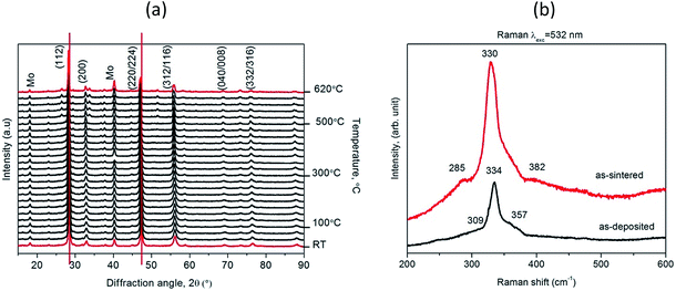 | ||
| Fig. 3 Temperature-dependent X-ray powder diffractograms of CZTS films from room temperature (RT) to 620 °C (a); Raman spectrum of an as-deposited CZTS film and an as-sintered CZTS film (b). | ||
The as-deposited CZTS film shows diffraction peaks without any secondary phases. In addition to the CZTS reflections observed at a temperature of 525 °C, some weaker reflections start to be discernible around 2θ = 26.6°, 33.7° and 51.72° probably due to formation of Cu4SnS4, MoS2 and ZnS phases, respectively.24,25 Heating the CZTS film from 450 to 620 °C causes a gradual shift of all kesterite reflections towards lower diffraction angles. This shift is mostly caused by the lattice expansion of the kesterite unit cell as a function of temperature.16,17
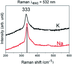
To study whether the as-sintered CZTS film contained any secondary phases that cannot be detected using XRPD, e.g. amorphous phases or phases with very similar crystal structures (e.g. ZnS and Cu2SnS3), Raman spectroscopy experiments were carried out. Fig. 3(b) and (c) illustrates a typical Raman spectrum of the CZTS film grown on Mo-coated soda–lime glass. Narrow peaks at 334 and 330 cm−1 belong to quaternary CZTS.21 Typical Raman spectra from the surface area of CZTS obtained peak at 338 cm−1. The displacement to low wavenumber from 338 to 330–334 cm−1 can be attributed to the existence of disorder effects in the cation sub-lattice in agreement with the non-stoichiometry conditions. The effect of samples with Cu-poor composition leads to the disorder in the Cu and Zn sub-lattices. This disordered kesterite phases qualitatively agree with those reported in ref. 26 and 27. The Raman bands at 285 and 382 cm−1 observed in the as-sintered CZTS film can be assigned to MoS2 phases.25 The sharpness and the strong intensity of the CZTS mode suggest that the films is highly crystalline in good agreement with in situ XRPD results. There are no additional bands related to the presence of other compounds, which means that a single-phase CZTS film was obtained.
Sintering of CZTS films: effect of alkali additives
Fig. 4(a) shows the as-deposited film of CZTS prepared by spin coating from the original CZTS powder-containing ink without alkali additives; Fig. 4(b) shows the CZTS film morphology after sintering at 620 °C in N2 atmosphere for 2 hours. SEM micrographs show that there is no obvious effect of sintering as both films reveal identical appearance.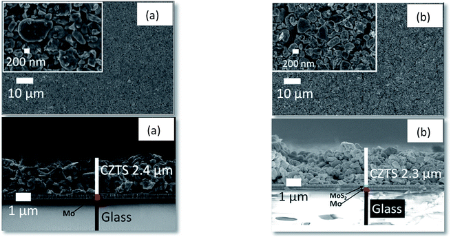 | ||
| Fig. 4 CZTS film surface and cross-sectional examinations of an as-deposited film (a) and as-sintered film (b). | ||
Alkali ions (Na and/or K) as sintering additives to initiate powder necking and to trigger the sintering process are also known to promote larger kesterite thin film grain growth deposited from molecular and nanoparticle-based inks.28–30 The concentration of Na and K ions added to the CZTS ink was varied by controlling their molar ratios to CZTS loading. It was expected that alkali addition assists the grain growth.28,31,32
The morphology of the as-sintered CZTS films prepared from inks containing various Na and K concentrations are shown in Fig. 6. For the sake of clarity, the morphological study was focused on the interface between CZTS and Mo. The gradual change of CZTS grain size and morphology from coarse to faceted grains can be seen as an effect of Na addition in the ink from 2 to 10 mol%. The size of CZTS grains also increases as Na assists CZTS re-crystallisation which yields a denser CZTS layer. The powders start to fuse as denoted by well-defined grain boundaries indicating an initial stage of the sintering process.33 At this stage, the atoms on the CZTS powder surface have higher diffusion rates, resulting in a smoother morphology. Thereby, necking takes place in the initial sintering stage. A higher Na content apparently modifies the powder further, as can be seen from the completely different film structure where faceted and uniform grains dominate. Na contents between 4–8 mol% lead to an intermediate stage of sintering as identified by the reduction of open pores intersecting grain boundaries while the powder reshapes its form towards more faceted grains. Additional Na content in the CZTS ink up to 10 mol% further reduces pores significantly and homogeneously recrystallizes the grains as a sign that the final stage of sintering has been achieved.
The Na contents in as-deposited and as-sintered films was measured by ICP as the sum of cations which average amounts to 6 at% and at%, respectively. The measurement was conducted for 3 samples with 1.76% and 0.29% of its standard deviations.
In contrast to effects of Na addition, already small amounts of K in the CZTS ink promotes immediate recrystallisation. As can be seen in Fig. 5, an addition of 2 mol% K is sufficient to recrystallise CZTS. K contents up to 10 mol% in the ink produce a dense and compact as-sintered CZTS film with almost no pores. This is in good agreement with the results of Haass et al. who reported that a heavier alkali element acts as a more effective sintering additive than a lighter one.13 The K contents in the as-deposited and as-sintered films determined by ICP/MS as the sum of cations are 6 at% and at%, with the standard deviations are 1.2% and 0.49%, respectively. The promoted CZTS film recrystallisation after addition of alkali ions can be explained by alkali-induced sintering process enhancement. Under the sintering conditions sulfur vapor exists that leads to formation of liquid phases of NaxS and KxS. These compounds can act as sulfur reservoirs34 and enable CZTS recrystallisation. The liquid alkali metal–S phases also enhance a uniform elemental diffusion of the CZTS constituent merging more CZTS grain boundaries. In our study, both molar concentrations of Na and K in the CZTS-powder containing ink were optimized at 10 and 2 mol%, respectively.
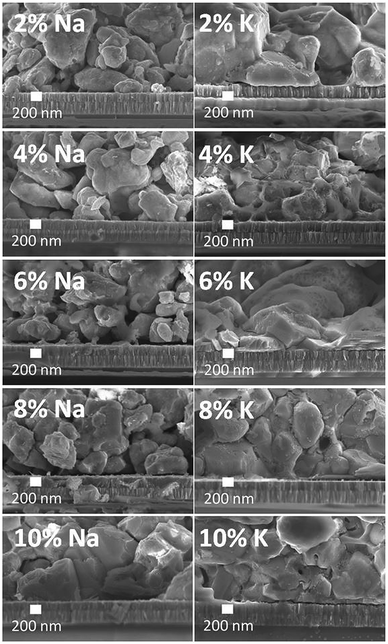 | ||
| Fig. 5 The sintering behaviour of CZTS films as a function of Na and K molar concentration in the CZTS inks. | ||
Evaluation of Raman spectra of the as-sintered CZTS films prepared from inks with alkali addition suggests the presence of a pure kesterite phase with the typical major vibration band at 333 cm−1.35 Bands of MoS2 in the alkali-containing CZTS film are missing which may be caused either from a thinner MoS2 layer or a thicker CZTS film (Fig. 6).
Chemical compositions as determined by ICP/MS of as-coated and as-sintered CZTS films prepared with and without alkali addition are collated in Table 1. The metal ratio in as-deposited CZTS film from a CZTS powder-containing ink was determined to be Cu/(Sn + Zn) = 0.75 and Zn/Sn = 1.39, which represents the original CZTS powder metallic ratio, i.e. a Cu-poor and Zn-rich kesterite phase. After sintering, the Cu content in all samples is virtually unchanged as it lies within measurement error below 2% of the ICP/MS.
| Absorber film | Treatment | Cu/(Sn + Zn) | STD | Zn/Sn | STD |
|---|---|---|---|---|---|
| No alkali addition | AC | 0.75 | 0.035 | 1.39 | 0.079 |
| AS | 0.80 | 0.011 | 1.32 | 0.021 | |
| 10 mol% Na | AC | 0.80 | 0.003 | 1.23 | 0.013 |
| AS | 0.78 | 0.006 | 1.33 | 0.017 | |
| 2 mol% K | AC | 0.78 | 0.003 | 1.20 | 0.012 |
| AS | 0.78 | 0.014 | 1.30 | 0.029 |
Sintering of CZTS films: effects of binder addition
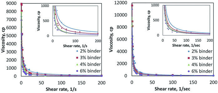
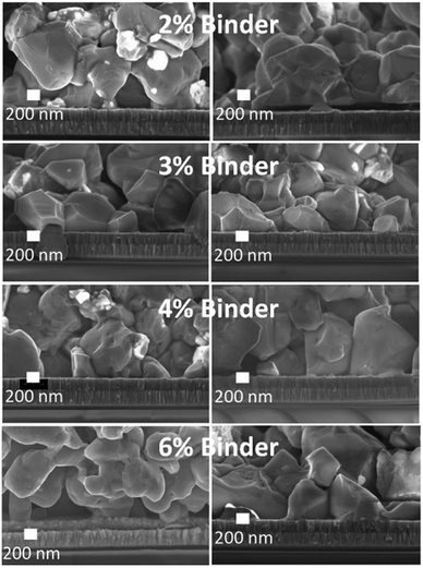
The CZTS powder-containing ink containing alkalis was further optimised through variation of the GA natural binder content in order to control the ink viscosity that is relevant for spin coating. Fig. 7 shows the viscosity of the ink as a function of GA concentration and applied shear stress. The CZTS ink does not show Newtonian behaviour since its viscosity decreases as the shear rate gradually rises. The ink viscosity saturates at 500 cP, regardless of its binder concentration. This ink viscosity is still in the range of a suitable ink viscosity for spin-coating.36Fig. 8 shows the effects of GA binder variation to the microstructure in CZTS films originating from inks with additional Na and K contents. Initial additions of GA binder from 2–4 wt% in the CZTS ink gives a negligible change in the morphology of the as-sintered CZTS films. Further gradual addition of GA binder results in morphological changes from faceted to irregular morphology and with size changes of the grains. Pores and cracks are found in the as-sintered CZTS films prepared from inks with high GA content. This is mainly caused by carbon residues from GA in the as-sintered CZTS films.37 Although the carbon concentration in the as-sintered CZTS film was not quantified, it is assumed that the carbon residue is proportional with the GA concentration in the ink. During sintering, GA incompletely evaporates and/or pyrolyses and leaves carbon residues on the surface of the CZTS grain that can form a carbon-coated layer. This layer inhibits grain growth that also leads to a CZTS film with smaller grain sizes.38,39
In summary, the presence of alkali cations (Na and K) and gum arabic binder in CZTS ink formulation leads to an interplay between these components on the microstructural properties of as-sintered CZTS films. High alkali contents in the ink enhance CZTS grain growth, whereas high GA binder contents inhibit CZTS grain growth. This result demonstrates that the addition of an organic binder in the CZTS powder-containing ink is identical with the effect of adding an organic solvent to nanoparticle-based or molecular-based kesterite CZTS inks.38 This confirms a detrimental effect of organic components in any solution-based processing of CZTS films. Therefore, the GA binder concentration should be high enough to improve the viscosity of a CZTS powder-containing ink, but low enough to allow grain growth during sintering. Taking into account the interplay between alkali cations (optimized at 10 mol% Na or 2 mol% K) and GA binder in the CZTS inks on as-sintered CZTS film properties, the GA binder quantity in CZTS inks was optimized to be 3 wt%.
Conclusions
This contribution demonstrates a preparation of dense and compact CZTS films from raw CZTS powder material. Various CZTS films prepared from CZTS powder-containing inks have been examined and optimized. Thermal analysis of CZTS powders in the sub-micron range using DTA-TG and in situ XRPD revealed that CZTS is chemically stable from room temperature to 620 °C. It is demonstrated that in order to produce a dense and compact CZTS film, sintering additives containing the alkali cations Na and K are required. Alkali addition in the CZTS powder-containing ink initiates grain necking and recrystallisation of CZTS, producing a denser as-sintered CZTS film. Although addition of both Na and K lead to CZTS recrystallisation, it is found that K promotes grain necking more effectively than Na. For the first time, the use of a natural gum of GA was also demonstrated as a binder in CZTS-powder containing ink. It was found that the optimisation of ink formulation to obtain lower ink viscosity through additional binder is limited by the binder grain growth inhibition effect. Therefore, an interplay between grain growth promoter (addition of Na and K) and ink viscosity modifier (binder) should be controlled with high Na and low K concentrations along with low binder addition.Conflicts of interest
There are no conflicts to declare.Acknowledgements
The authors gratefully acknowledge financial support from the SOLAR-ERA-NET project SPRINT-CELL (Austrian FFG Contract No. 853374). Raman spectroscopic measurements were performed with the help of Phillip Baloh at TU Wien, in situ XRPD was carried out in the X-ray Centre of TU Wien with the help of Werner Artner, and ICP measurements were conducted by Christopher Herzig at TU Wien. A. M. would like to acknowledge Österreichischer Austauschdienst (OeAD) for financial support through the ASEA-UNINET Ernst Mach Grant Scholarship.References
- A. Polman, M. Knight, E. C. Garnett, B. Ehrler, W. C. Sinke, R. Summary, A. Polman, M. Knight, E. C. Garnett, B. Ehrler, W. C. Sinke and R. Summary, Science, 2016, 352, 307 CrossRef CAS.
- P. Y. Gan and Z. Li, Renewable Sustainable Energy Rev., 2015, 46, 88–99 CrossRef.
- W. Wang, M. T. Winkler, O. Gunawan, T. Gokmen, T. K. Todorov, Y. Zhu and D. B. Mitzi, Adv. Energy Mater., 2014, 4, 1–5 CrossRef.
- C. Yan, J. Huang, K. Sun, S. Johnston, Y. Zhang, H. Sun, A. Pu, M. He, F. Liu, K. Eder, L. Yang, J. M. Cairney, N. J. Ekins-Daukes, Z. Hameiri, J. A. Stride, S. Chen, M. A. Green and X. Hao, Nat. Energy, 2018, 3, 764–772 CrossRef CAS.
- S. Abermann, Sol. Energy, 2013, 94, 37–70 CrossRef CAS.
- D. B. Mitzi, O. Gunawan, T. K. Todorov and D. A. R. Barkhouse, Philos. Trans. R. Soc., A, 2013, 371, 1–22 CrossRef.
- J. Guo, Y. Pei, Z. Zhou, W. Zhou, D. Kou and S. Wu, Nanoscale Res. Lett., 2015, 10, 1–6 CrossRef.
- W. Li, J. M. R. Tan, S. W. Leow, S. Lie, S. Magdassi and L. H. Wong, Energy Technol., 2018, 6, 46–59 CrossRef CAS.
- F. Gaspari and S. Quaranta, 2.5 PV Materials, Elsevier Ltd., 2018, vol. 2 Search PubMed.
- S. F. Wang and T. C. Yang, J. Mater. Res., 2000, 15, 407–416 CrossRef CAS.
- Y. Iqbal, A. Jamal, R. Ullah, M. N. Khan and R. Ubic, Bull. Mater. Sci., 2012, 35, 387–394 CrossRef CAS.
- J. Zhang, Y. Zong and T. Ma, Experiment research on lowering sintering temperature of ceramic based on steel slag, in International Forum on Energy, Environment and Sustainable Development (IFEESD 2016), Atlantis Press, 2016, pp. 634-638 Search PubMed.
- S. G. Haass, C. Andres, R. Figi, C. Schreiner, M. Bürki, Y. E. Romanyuk and A. N. Tiwari, Adv. Energy Mater., 2018, 8, 1–9 Search PubMed.
- R. A. Wibowo, Sol. Energy, 2018, 176, 157–169 CrossRef CAS.
- J. J. Scragg, T. Ericson, T. Kubart, M. Edoff and C. Platzer-Björkman, Chem. Mater., 2011, 23, 4625–4633 CrossRef CAS.
- B. R. C. Sharma and Y. A. Chang, J. Phase Equilib., 1986, 7, 269–273 Search PubMed.
- D. J. Chakrabati and D. E. Laughlin, Bull. Alloy Phase Diagrams, 1983, 4, 254–271 CrossRef.
- Landolt-Bornstein-Database, 1991, vol. 1–3 Search PubMed.
- H. Matsushita and T. Takizawa, J. Cryst. Growth, 1997, 179, 503–509 CrossRef CAS.
- S. Schorr, A. Weber, V. Honkimäki and H. W. Schock, Thin Solid Films, 2009, 517, 2461–2464 CrossRef CAS.
- S. Schorr, Sol. Energy Mater. Sol. Cells, 2011, 95, 1482–1488 CrossRef CAS.
- H. Matsushita, S. i. Ai and A. Katsui, J. Cryst. Growth, 2001, 224, 95–100 CrossRef CAS.
- Crystallography Open Database, http://crystallography.net/cod/, accessed 16 July 2019 Search PubMed.
- R. Schurr, A. Hölzing and R. Hock, Thin Solid Films, 2011, 519, 7412–7415 CrossRef CAS.
- D. M. Berg, M. Arasimowicz, R. Djemour, L. Gütay, S. Siebentritt, S. Schorr, X. Fontané, V. Izquierdo-Roca, A. Pérez-Rodriguez and P. J. Dale, Thin Solid Films, 2014, 569, 113–123 CrossRef CAS.
- M. Y. Valakh, O. F. Kolomys, S. S. Ponomaryov, V. O. Yukhymchuk, I. S. Babichuk, V. Izquierdo-Roca, E. Saucedo, A. Perez-Rodriguez, J. R. Morante, S. Schorr and I. V. Bodnar, Phys. Status Solidi RRL, 2013, 7, 258–261 CrossRef CAS.
- M. Hurtado, E. Ramírez, E. Romero and G. Gordillo, XXIII Int. Mater. Res. Congr., 2014, 3036 Search PubMed.
- S. Sahayaraj, G. Brammertz, B. Vermang, A. Mule, T. Schnabel, M. Meuris, J. Vleugels and J. Poortmans, J. Mater. Chem. A, 2018, 6, 2653–2663 RSC.
- P. Reinhard, B. Bissig, F. Pianezzi, E. Avancini, H. Hagendorfer, D. Keller, P. Fuchs, M. Do, C. Vigo, P. Crivelli, S. Nishiwaki, S. Buecheler and A. N. Tiwari, Chem. Mater., 2015, 27, 5755–5764 CrossRef CAS.
- D. Rudmann, Effects of sodium on growth and properties of Cu(In,Ga)Se2 thin films and solar cells, Doctoral thesis, ETH Zurich, 2004 DOI:10.3929/ethz-a-004796411.
- S. G. Haass, C. Andres, R. Figi, C. Schreiner, M. Bürki, A. N. Tiwari and Y. E. Romanyuk, AIP Adv., 2018, 8, 015133 CrossRef.
- H. Kirou, L. Atourki, K. Abouabassi, A. Soltani, A. Almaggoussi, A. Elfanaoui, K. Bouabid, M. Nya and A. Ihlal, Opt. Mater., 2018, 75, 471–482 CrossRef CAS.
- J. S. Reed, Principles of Ceramics Processing, John Wiley and Sons, Canada, 2nd edn, 1995 Search PubMed.
- D. P. Shoemaker, Y.-J. Hu, D. Y. Chung, G. J. Halder, P. J. Chupas, L. Soderholm, J. F. Mitchell and M. G. Kanatzidis, Proc. Natl. Acad. Sci. U. S. A., 2014, 111, 10922–10927 CrossRef CAS.
- G. L. Frey and R. Tenne, Phys. Rev. B: Condens. Matter Mater. Phys., 2000, 60, 2883–2892 CrossRef.
- Y. E. Romanyuk, C. M. Fella, A. R. Uhl, M. Werner, A. N. Tiwari, T. Schnabel and E. Ahlswede, Sol. Energy Mater. Sol. Cells, 2013, 119, 181–189 CrossRef CAS.
- R. Edla, N. Ataollahi, C. Malerba, R. Ciancio, P. Scardi, E. Cappelletto and R. Di Maggio, Thin Solid Films, 2019, 674, 12–21 CrossRef.
- V. T. Tiong, Y. Zhang, J. Bell and H. Wang, RSC Adv., 2015, 5, 20178–20185 RSC.
- B. D. Chernomordik, A. E. Béland, D. D. Deng, L. F. Francis and E. S. Aydil, Chem. Mater., 2014, 26, 3191–3201 CrossRef CAS.
| This journal is © The Royal Society of Chemistry 2019 |

