 Open Access Article
Two dimensional ZnO/AlN composites used for photocatalytic water-splitting: a hybrid density functional study
Guangzhao Wang†
 *a,
Yumo Li†a,
Ling Zhanga,
Junli Changb,
Yadong Lia,
Liangping Xiaa,
Shuyuan Xiao
 c,
Suihu Danga and
Chunxia Lia
aSchool of Electronic Information Engineering, Key Laboratory of Extraordinary Bond Engineering and Advanced Materials Technology of Chongqing, Yangtze Normal University, Chongqing 408100, China. E-mail: wangyan6930@126.com; wangyan6930@yznu.edu.cn
bSchool of Physical Science and Technology, Southwest University, Chongqing 400715, China
cInstitute for Advanced Study, Nanchang University, Nanchang 330031, China
First published on 7th November 2019
Abstract
Using hybrid density functionals, we study the interfacial interactions and electronic properties of ZnO/AlN composites with the consideration of rotation angles and biaxial strains in order to enhance the photocatalytic performance for water-splitting. The different rotated composites, and −2% strained, original, and 2% strained ZnO/AlN composites can be easily prepared owing to the negative interface formation energies. The bandgaps and band alignments of ZnO/AlN composites can be significantly tuned by biaxial strains. Particularly, the appropriate bandgap for visible light absorption, proper band alignment for spontaneous water-splitting, and the formed electric field promoting photoinduced carrier separation make the 2% strained ZnO/AlN composite a potential candidate for photocatalytic water-splitting. This work shines some light on designing two dimensional heterostructured photocatalysts.
1 Introduction
Photocatalytic water-splitting offers a new method for environmental remediation and energy supply through generating clean and recyclable hydrogen by means of either sunlight or artificial light.1–4 Since TiO2![[thin space (1/6-em)]](https://www.rsc.org/images/entities/char_2009.gif) 5 was reported to have the ability to split water into hydrogen and oxygen in 1972, many scientists have devoted their efforts to develop efficient photocatalysts. To be an ideal water-splitting photocatalyst, it should satisfy the following conditions: (a) the bandgap (Eg) for the semiconductor should be adapted to utilize visible light, accounting for 43% of solar energy,6,7 (b) the conduction band maximum (CBM) must be high enough to allow photoinduced electrons to reduce water, while the valence band maximum (VBM) must be low enough to allow photogenerated holes to oxidize water,8,9 and (c) the carriers must possess a lower recombination rate and higher mobility.10,11 Balancing these conditions will affect the photocatalytic activity of a photocatalyst.
5 was reported to have the ability to split water into hydrogen and oxygen in 1972, many scientists have devoted their efforts to develop efficient photocatalysts. To be an ideal water-splitting photocatalyst, it should satisfy the following conditions: (a) the bandgap (Eg) for the semiconductor should be adapted to utilize visible light, accounting for 43% of solar energy,6,7 (b) the conduction band maximum (CBM) must be high enough to allow photoinduced electrons to reduce water, while the valence band maximum (VBM) must be low enough to allow photogenerated holes to oxidize water,8,9 and (c) the carriers must possess a lower recombination rate and higher mobility.10,11 Balancing these conditions will affect the photocatalytic activity of a photocatalyst.
Recently, two-dimensional (2D) materials, such as MoS2,12 g-C3N4,13,14 C2N,15,16 etc., have exhibited bright promise in the area of photocatalysis owing to their excellent carrier mobility, specific surface area, good stability and tunable interfaces. Recently, ZnO nanosheets have been reported to be experimentally synthesized. Tushce et al.17 prepared a ZnO nanosheet, which was loaded onto an Ag (111) surface, with O and Zn atoms arranged in a graphene-like planar structure. Besides, Claeyssens et al.18 also proved that the thin ZnO (001) surface film possesses a graphene-like structure. Especially, Kang et al.19 reported that under ultraviolet irradiation the prepared ZnO nanosheet showed excellent ability for photocatalytic degradation of RhB. Besides, many theoretical studies are focused on the magnetism of a ZnO single-layer.20,21 However, few studies concentrate on the photocatalytic water-splitting of a ZnO single-layer. This may be due to the fact that a ZnO single-layer possesses a large bandgap of 3.25 eV,22,23 which obviously limits its ability for visible light utilization, leading to a low hydrogen evolution efficiency. Thus, some strategies have to be taken to reduce the bandgap and enhance photocatalytic performance.
Constructing a heterostructure is an effective way to enhance the photocatalytic performance because the reduced bandgap can effectively improve the ability for visible light absorption and the formed electric field can obviously promote the photoinduced carrier separation.24–26 Lots of composites, such as CdS/g-C3N4,27,28 AlN/WS2,29 GaN/WS2,30 WS2/Mg(OH)2,31 C2N/WS2,32 InSe/C3N4,33 g-C3N4/SnS2,34 BP/MoS2,35 g-C3N4/WS2,36 etc., exhibit excellent photocatalytic activity. In particular, a series of ZnO single-layer based composites including ZnO/GeC,37 ZnO/MoS2,38 and ZnO/WS2 (ref. 39) have also been adapted for overall photocatalytic water-splitting. This encourages us to design more efficient ZnO-based composites to be used as water-splitting photocatalysts. The AlN monolayer and ZnO monolayer share a similar crystal structure and lattice constants,40,41 which is beneficial for the experimental preparation of ZnO/AlN composites. We wonder whether the possible ZnO/AlN composite is adapted for efficient photocatalytic water-splitting. Besides, we are also curious whether the biaxial strains and the pH of the electrolyte can significantly enhance the photocatalytic activity of the ZnO/AlN composite. To solve these problems, a detailed study on the photocatalytic water-splitting of the ZnO/AlN composite is needed.
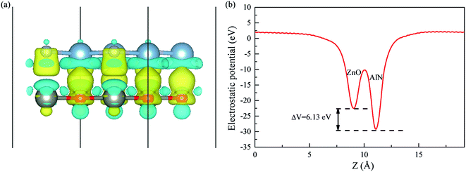
In this work, we present systematic research on the photocatalytic properties of ZnO/AlN composites by the use of hybrid density functionals. We load different rotated AlN monolayers on a fixed ZnO monolayer to construct rotated ZnO/AlN composites. However, the bandgap of the most stable composite is too large to absorb visible light. Then, we apply biaxial strains to modulate the bandgaps of the ZnO/AlN composites. We find that the 2% strained composite possesses an adapted bandgap for visible light utilization and appropriate alignment for spontaneous hydrogen and oxygen production. Besides, the charge transfer from the AlN layer to the ZnO layer leads to an electric field across the interface region, which inhibits the photoexcited carrier recombination. Our theoretical findings open up new possibilities to design efficient water-splitting photocatalysts based on ZnO and AlN single-layers.
2 Computational details
Our calculations are operated using density functional theory (DFT) with the projector augmented wave (PAW)42,43 approach and generalized gradient approximation (GGA)44 of the Perdew–Burke–Ernzerhof (PBE)45 function, and are implemented by the Vienna ab initio simulation package (VASP).46,47 The valence electrons are constructed as: Zn (3d104s2), O (2s22p4), Al (3s23p1), and N (2s22p3). A vacuum space of 20 Å perpendicular to the layers is utilized to separate the neighboring slab interactions. The cutoff energy is 500 eV, the force convergence criteria is 0.01 eV Å−2, and the energy convergence tolerance is 10−5 eV. The k-point for ZnO and AlN cells is set as 13 × 13 × 1, while the k-point for ZnO/AlN composites is set as 7 × 7 × 1. These settings are sufficient for geometrical optimization and total energy calculation. To precisely describe the electronic and optical properties, we employ Heyd–Scuseria–Ernzerhof (HSE).48 HSE of Hartree–Fock exchange energy of 25% and 10% can ensure the bandgaps for ZnO and AlN single-layers are consistent with the previous experimental and theoretical values. We adopt the average value of 25% and 10% to treat the electronic structures of ZnO/AlN composites, and a similar strategy has been employed to treat the electronic structures of some other semiconductor composites.49,503 Results and discussion
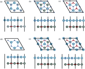
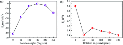
Firstly, we optimize the structures of ZnO and AlN single-layers. The gained lattice constants are 3.290 and 3.127 Å for the ZnO and AlN single-layers, and the Zn–O and Al–N bond lengths are 1.892 and 1.895 Å, respectively. Besides, the obtained bandgaps for the ZnO and AlN single-layers are individually 3.30 and 3.36 eV. These results are consistent with the previously reported values.8,22,29,39 We construct the models of ZnO/AlN composites through loading a rotated 2 × 2 AlN single-layer at different angles from 0° to 360° with 60° apart on a fixed 2 × 2 ZnO single-layer, resulting in a lattice mismatch of −4.95%, which ensures the possibility of experimental preparation of the ZnO/AlN composites. The corresponding stacked configurations are shown in Fig. 1.To discuss the stability of the ZnO/AlN composites, we compute the interface formation energy (Ef) by the equation: Ef = EZnO/AlN − EZnO − EAlN, in which EZnO/AlN, EZnO, and EAlN are the total energies of the composite, ZnO monolayer, and AlN monolayer, respectively. Fig. 2 plots the varied Ef and Eg values of different rotated ZnO/AlN composites. The Ef increases from 0° to 180° and falls from 180° to 360°. All the Ef values are negative, which suggests that the synthesis of these structures is exothermic, which is favorable for experimental preparation. Besides, the rotated configuration of 0° has the smallest Ef value of −61.6 meV Å−2, which means this composite is the most stable structure among all the configurations we considered. Besides, the Ef value is obviously larger than the previous vdW binding energy of about 20 meV Å−2 obtained by DFT calculation, thus the composite can be stably synthesized. The varied Eg values of the different rotated ZnO/AlN composites are 3.01, 2.41, 2.55, 2.49, 2.46, and 2.40 eV, which suggests the most stable composite of 0° is unfavorable for visible light absorption because of the large bandgap.
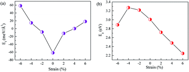
Commonly, external strain usually has a significant impact on the bandgaps and band alignments of semiconductors. Many previous studies51–53 report the successful application of biaxial strain to improve photocatalytic properties for water-splitting. Herein, we also apply biaxial strain to modulate the bandgaps and band alignments so as to enhance the photocatalytic performance of ZnO/AlN composites for water-splitting. The biaxial strain is calculated by the equation: ε = (c − c0)/c0 × 100%, in which c and c0 represent the lattice parameters of the strained and original supercells, respectively, of the ZnO/AlN composites. Fig. 3 lists the varied Ef and Eg values of different biaxial strained ZnO/AlN composites. The Ef values fall in the strain range from −6% to 0 but increase in the strain range from 0 to 6%. The Ef values of the different strained composites are 58.42, 14.87, −8.57, −61.59, −12.11, 0.25, and 18.37 eV Å−2. The Ef values of the strained composites of ε = −2%, 0, and 2% are negative, suggesting these composites can be experimentally prepared. The gained Eg values for the different strained composites are 2.89, 3.27, 3.22, 3.01, 2.72, 2.48, and 2.25 eV. The bandgaps for the composites of ε = 2%, 4%, and 6% are favorable for absorbing visible light.
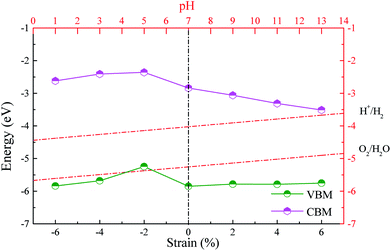
An efficient photocatalyst should not only possess a suitable bandgap for fully using visible light but also have proper band alignments with respect to the water redox potentials. Namely, the CBM and VBM must be respectively above the H+/H2 potential and below the O2/H2O potential. It is well known that the standard hydrogen electrode potential relies on the pH values. The potentials of H+/H2 and O2/H2O are separately calculated by EH+/H2 = −4.44 eV + pH × 0.059 eV (ref. 54) and EO2/H2O = EH+/H2 − 1.23 eV = −5.67 eV + pH × 0.059 eV.55 We give the band alignments of the ZnO/AlN composites relative to the water redox levels in Fig. 4. The band edges of the strained composite of ε = −2% span the water redox levels within the pH range of 7.2–14, implying this strained composite is beneficial for spontaneous hydrogen and oxygen production in the proper pH range. The strained composites of ε = −6%, −4%, 0, 2%, 4%, and 6% span the water redox potentials within the pH range of 0–14, which means that these strained composites are thermodynamically beneficial for both oxidation and reduction reactions in any pH value, i.e., the photocatalytic properties of these strained composites are not limited by the pH value. Besides, the strained composites of ε = 2%, 4%, and 6% are also suitable for absorbing visible light. Especially, the composite of ε = 2% is easy to be experimentally prepared due to the negative interface formation energy. The strained ZnO/AlN of ε = 2% is a promising candidate for photocatalytic water-splitting. Thus, the following discussion is focused on the ZnO/AlN of ε = 2%.
To explore the physical essence of the ZnO/AlN composite, we plot the density of states (DOS), projected density of states (PDOS), and band structures of the strained ZnO/AlN composite (see Fig. 5). The ZnO/AlN composite is an indirect bandgap semiconductor as the VBM and CBM respectively sit at the different points of K and Γ. The VBM of the ZnO/AlN composite is dominated by Zn 3p, Zn 3d, O 2p, and N 2p states, while the CBM mainly consists of Zn 4s, O 2s, and N 2s states. Considering the electronic transition of angular momentum selection rules of Δl = ±1, after absorbing photons the electrons below the Fermi level will be excited from N 2p, O 2p, and Zn 3p states to Zn 4s, O 2s, and N 2s states.
 | ||
| Fig. 5 (a) DOS, (b) PDOS, and (c) band structures of the 2% strained ZnO/AlN composite. The Fermi level is set to zero. | ||
We also calculate the three-dimensional charge density difference of the ZnO/AlN composite to acquire the charge redistribution across the interface region. The formula for the corresponding calculation is:
| Δρ = ρZnO/AlN − ρZnO − ρAlN | (1) |
The optical absorption is another indispensable factor to judge the photocatalytic properties of semiconductors. The photo-absorption coefficient is determined by the real part and imaginary part of the complex dielectric function56
| ε(ω) = ε1(ω) + iε2(ω) | (2) |
 | (3) |
 | (4) |
 | (5) |
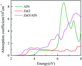
We show the calculated optical spectra of the ZnO/AlN composite, ZnO monolayer, and AlN monolayer in Fig. 7. The ZnO and AlN single-layers can hardly absorb visible light owing to their wide bandgaps. On the contrary, the absorption curve of the strained ZnO/AlN composite of ε = 2% obviously shifts forward to the visible light region. Consequently, we can make the conclusion that the ZnO/AlN composite of ε = 2% is a promising water-splitting photocatalyst.
4 Conclusions
In summary, we designed different rotated and biaxial strained ZnO/AlN composites so as to enhance the photocatalytic performance for water-splitting. The different rotated composites and the strained composites of ε = −2%, 0, and 2% can be experimentally prepared due to the negative interface formation energies. Biaxial strains can effectively modulate the bandgaps and band alignments. Especially, the strained composite of ε = 2% possesses an appropriate bandgap for fully utilizing visible light and appropriate band alignments for spontaneous water-splitting. Besides, the electrons transferring from the AlN to ZnO layer result in an electric field around the interface region, promoting photoinduced carrier separation and improving photocatalytic activity. These predications indicate that the 2% strained ZnO/AlN composite is a promising water-splitting photocatalyst.Conflicts of interest
There are no conflicts to declare.Acknowledgements
This work was supported by the National Natural Science Foundation of China under Grant No. 11847100, the Natural Science Foundation of Chongqing under Grant No. cstc2019jcyj-msxmX0376, the Science and Technology Plan Project of Fuling District under Grant No. FLKJ, 2018BBA3056, and the China Scholarship Council under Grant No. 201909955001.References
- M. R. Hoffmann, S. T. Martin, W. Choi and D. W. Bahnemann, Chem. Rev., 1995, 95, 69–96 CrossRef CAS.
- M. Gratzel, Nature, 2001, 414, 338–344 CrossRef CAS.
- X. Chen, S. Shen, L. Guo and S. S. Mao, Chem. Rev., 2010, 110, 6503–6570 CrossRef CAS.
- C. Fu, X. Wu and J. Yang, Adv. Mater., 2018, 30, 1802106 CrossRef.
- A. Fujishima and K. Honda, Nature, 1972, 238, 37–38 CrossRef CAS.
- G. Wang, H. Chen, Y. Li, A. Kuang, H. Yuan and G. Wu, Phys. Chem. Chem. Phys., 2015, 17, 28743–28753 RSC.
- Y. Fan, B. Yang, X. Song, X. Shao and M. Zhao, J. Phys. D: Appl. Phys., 2018, 51, 395501 CrossRef.
- J. Liao, B. Sa, J. Zhou, R. Ahuja and Z. Sun, J. Phys. Chem. C, 2014, 118, 17594–17599 CrossRef CAS.
- G. Wang, Y. Huang, A. Kuang, H. Yuan, Y. Li and H. Chen, Inorg. Chem., 2016, 55, 9620–9631 CrossRef CAS.
- B. Modak and S. K. Ghosh, J. Phys. Chem. C, 2015, 119, 7215–7224 CrossRef CAS.
- G. Wang, X. Long, K. Qi, S. Dang, M. Zhong, S. Xiao and T. Zhou, Appl. Surf. Sci., 2019, 471, 162–167 CrossRef CAS.
- Z. Li, X. Meng and Z. Zhang, J. Photochem. Photobiol., C, 2017, 35, 39–55 CrossRef.
- J. Fu, J. Yu, C. Jiang and B. Cheng, Adv. Energy Mater., 2018, 8, 1701503 CrossRef.
- W. Ong, L. Tan, Y. H. Ng, S. Yong and S. Chai, Chem. Rev., 2016, 116, 7159–7329 CrossRef CAS.
- L. Wang, X. Zheng, L. Chen, Y. Xiong and H. Xu, Angew. Chem., Int. Ed., 2018, 57, 3454–3458 CrossRef CAS.
- M. R. A. Kishore and P. Ravindran, ChemPhysChem, 2017, 18, 1526–1532 CrossRef CAS.
- C. Tusche, H. L. Meyerheim and J. Kirschner, Phys. Rev. Lett., 2007, 99, 026102 CrossRef CAS.
- F. Claeyssens, C. L. Freeman, N. L. Allan, Y. Sun, M. N. R. Ashfold and J. H. Harding, J. Mater. Chem., 2005, 15, 139–148 RSC.
- S. Kang, T. Wu, X. Li and J. Mu, Colloids Surf., 2010, 369, 268–271 CrossRef CAS.
- F. Li, C. Zhang and M. Zhao, Phys. E, 2013, 53, 101–105 CrossRef CAS.
- T. M. Schmidt, R. H. Miwa and A. Fazzio, Phys. Rev. B: Condens. Matter Mater. Phys., 2010, 81, 195413 CrossRef.
- H. Guo, Y. Zhao, N. Lu, E. Kan, X. C. Zeng, X. Wu and J. Yang, J. Phys. Chem. C, 2012, 116, 11336–11342 CrossRef CAS.
- X. Luo, G. Wang, Y. Huang, B. Wang, H. Yuan and H. Chen, J. Phys. Chem. C, 2017, 121, 18534–18543 CrossRef CAS.
- Z. Wang, Y. Liu, B. Huang, Y. Dai, Z. Lou, G. Wang, X. Zhang and X. Qin, Phys. Chem. Chem. Phys., 2014, 16, 2758–2774 RSC.
- H. Jin, Y. Dai and B. Huang, Sci. Rep., 2016, 6, 23104 CrossRef CAS.
- W. Zan, W. Geng, H. Liu and X. Yao, J. Alloys Compd., 2016, 666, 204–208 CrossRef CAS.
- G. Wang, F. Zhou, B. Yuan, S. Xiao, A. Kuang, M. Zhong, S. Dang, X. Long and W. Zhang, Nanomaterials, 2019, 9, 244 CrossRef CAS.
- J. Li, W. Wei, C. Mu, B. Huang and Y. Dai, Phys. E, 2018, 103, 459–463 CrossRef CAS.
- G. Z. Wang, S. Dang, Z. Peng, S. Xiao and M. Zhong, J. Phys. D: Appl. Phys., 2018, 51, 025109 CrossRef.
- G. Wang, S. Dang, W. Zhao, Y. Li, S. Xiao and M. Zhong, Phys. Status Solidi B, 2018, 255, 1800133 CrossRef.
- Y. Luo, S. Wang, K. Ren, J.-P. Chou, J. Yu, Z. Sun and M. Sun, Phys. Chem. Chem. Phys., 2019, 21, 1791–1796 RSC.
- R. Kumar, D. Das and A. K. Singh, J. Catal., 2018, 359, 143–150 CrossRef CAS.
- Y. Liang, C. Long, J. Li, H. Jin, B. Huang and Y. Dai, ACS Appl. Energy Mater., 2018, 1, 5394–5401 CAS.
- S.-H. Chen, J.-J. Wang, J. Huang and Q.-X. Li, Chin. J. Chem. Phys., 2017, 30, 36 CrossRef CAS.
- G. Wang, W. Zhao, M. Zhong, Y. Li, S. Xiao, S. Dang, C. Li, X. Long and W. Zhang, J. Phys.: Condens. Matter, 2019, 31, 465002 CrossRef.
- X. Ma, C. Chen, J. Hu, M. Zheng, H. Wang, S. Dong, C. Huang and X. Chen, J. Alloys Compd., 2019, 788, 1–9 CrossRef CAS.
- X. Gao, Y. Shen, Y. Ma, S. Wu and Z. Zhou, J. Mater. Chem. C, 2019, 7, 4791–4799 RSC.
- G. Wang, H. Yuan, J. Chang, B. Wang, A. Kuang and H. Chen, RSC Adv., 2018, 8, 10828–10835 RSC.
- G. Wang, D. Li, Q. Sun, S. Dang, M. Zhong, S. Xiao and G. Liu, Nanomaterials, 2018, 8, 374 CrossRef.
- Y. Kadioglu, F. Ersan, D. Kecik, O. Ü. Aktürk, E. Aktürk and S. Ciraci, Phys. Chem. Chem. Phys., 2018, 20, 16077–16091 RSC.
- J. Lee, D. C. Sorescu and X. Deng, J. Phys. Chem. Lett., 2016, 7, 1335–1340 CrossRef CAS.
- P. E. Blochl, Phys. Rev. B: Condens. Matter Mater. Phys., 1994, 50, 17953–17979 CrossRef.
- G. Kresse and D. Joubert, Phys. Rev. B: Condens. Matter Mater. Phys., 1999, 59, 1758–1775 CrossRef CAS.
- J. P. Perdew, K. Burke and M. Ernzerhof, Phys. Rev. Lett., 1996, 77, 3865–3868 CrossRef CAS PubMed.
- M. Ernzerhof and G. E. Scuseria, J. Chem. Phys., 1999, 110, 5029–5036 CrossRef CAS.
- G. Kresse and J. Hafner, Phys. Rev. B: Condens. Matter Mater. Phys., 1993, 47, 558–561 CrossRef CAS.
- G. Kresse and J. Furthmuller, Phys. Rev. B: Condens. Matter Mater. Phys., 1996, 54, 11169–11186 CrossRef CAS.
- J. Heyd, G. E. Scuseria and M. Ernzerhof, J. Chem. Phys., 2003, 118, 8207–8215 CrossRef CAS.
- Z. Wang, M. Zhao, X. Wang, Y. Xi, X. He, X. Liu and S. Yan, Phys. Chem. Chem. Phys., 2012, 14, 15693–15698 RSC.
- T. Shimazaki and Y. Asai, J. Chem. Phys., 2010, 132, 224105 CrossRef.
- K. Ren, S. Wang, Y. Luo, Y. Xu, M. Sun, J. Yu and W. Tang, RSC Adv., 2019, 9, 4816–4823 RSC.
- X. Zhang, A. Chen, Z. Zhang, M. Jiao and Z. Zhou, Nanoscale Adv., 2019, 1, 154–161 RSC.
- G. Wang, S. Dang, P. Zhang, S. Xiao, C. Wang and M. Zhong, J. Phys. D: Appl. Phys., 2018, 51, 025109 CrossRef.
- V. Chakrapani, J. C. Angus, A. B. Anderson, S. D. Wolter, B. R. Stoner and G. U. Sumanasekera, Science, 2007, 318, 1424–1430 CrossRef CAS.
- A. K. Singh, K. Mathew, H. L. Zhuang and R. G. Hennig, J. Phys. Chem. Lett., 2015, 6, 1087–1098 CrossRef CAS.
- S. Saha, T. Sinha and A. Mookerjee, Phys. Rev. B: Condens. Matter Mater. Phys., 2000, 62, 8828 CrossRef CAS.
- F. Tian and C. Liu, J. Phys. Chem. B, 2006, 110, 17866–17871 CrossRef CAS.
- Q. Fu, T. He, J. Li and G. Yang, J. Appl. Phys., 2012, 112, 104322 CrossRef.
Footnote |
| † These authors contributed equally to this work. |
| This journal is © The Royal Society of Chemistry 2019 |

