 Open Access Article
Efficiencies and mechanisms of the chemical cleaning of fouled polytetrafluoroethylene (PTFE) membranes during the microfiltration of alkali/surfactant/polymer flooding oilfield wastewater†
Bing Zhang *abc,
Shuili Yu
 d,
Youbing Zhud,
Yu Shenab,
Xu Gaoab,
Wenxin Shi*e and
Joo Hwa Tayc
aNational Base of International Science and Technology Cooperation for Intelligent Manufacturing Service, Chongqing Key Laboratory of Catalysis & New Environmental Materials, Chongqing Technology and Business University, Chongqing 400067, China. E-mail: hitzhangbing@163.com
bChongqing South-to-Thais Environmental Protection Technology Research Institute Co., Ltd., Chongqing 400060, China
cDepartment of Civil Engineering, University of Calgary, Calgary T2N 1N4, Canada
dSchool of Environmental Science and Engineering, State Key Laboratory of Pollution Control and Resource Reuse, Tongji University, Shanghai 200092, China
eSchool of Environmental and Ecology, Chongqing University, Chongqing 400044, China. E-mail: swx@hit.edu.cn
First published on 13th November 2019
Abstract
The chemical cleaning of fouled polytetrafluoroethylene (PTFE) membranes with different reagents after the microfiltration of alkali/surfactant/polymer (ASP) flooding oilfield wastewater was examined in this study. Foulant analyses, cleaning efficiencies of different reagents and conditions and cleaning mechanisms were investigated. The results showed that anionic polyacrylamide (APAM) and crude oil were the main membrane foulants accompanied by organic–inorganic–organic/membrane aggregate foulants formed by bridging inorganic ions and organic species. Cleaning efficiency of 93% was acquired through mixed cleaning with 0.04 N NaClO + 200 mg L−1 NaOH, which was found to be better than individual cleaning. Moreover, consecutive cleaning with NaClO + NaOH–HCl restored 98% of the membrane flux, suggesting that HCl cleaning contributed to flux recovery. Additionally, the cleaning temperature and time were set as 40 °C and 3 h, respectively, considering economy and membrane lifespan. Finally, the mechanism of membrane cleaning and analyses of membrane properties were described in this paper, aiming to provide a future direction for production practices. Considering that the cleaning reagents used in this study are easy to obtain and use, consecutive cleaning with NaClO + NaOH–HCl is recommended to clean the PTFE membranes fouled by ASP flooding oilfield wastewater.
1. Introduction
In recent decades, alkali/surfactant/polymer (ASP) flooding oilfield wastewater is being increasingly produced during the oil recovery process.1–3 This wastewater needs to be processed prior to getting discharged into the environment to avoid the risk of severe pollution caused by its organic and inorganic components.1 Many countries that possess oilfields are seeking efficient and cost effective methods to manage this wastewater.4,5 In some oilfields, conventional techniques have been used to treat the wastewater; however, the emulsified and soluble oils in the wastewater cannot be effectively disposed.6 Membrane separation has emerged as a promising alternative for oilfield wastewater treatment due to its superior properties, including good selectivity, strong adaptability, and chemical composition retention.7–9 Microfiltration (MF) is considered to be one of the most effective membrane applications among the membrane separation processes for oilfield wastewater treatment.2,3,10 However, the pH of the wastewater has been observed to exceed the tolerable limit of commonly used MF membranes, which significantly shortens the membrane lifespan and increases operating costs. As an MF membrane, polytetrafluoroethylene (PTFE) is considered to be the best due to its high resistance to strong acids and alkalis, high and low temperatures, and corrosion. Thus, it is preferred for ASP flooding oilfield wastewater treatment.1,2,10–12 However, one of the obstacles impeding the large-scale development of MF is membrane fouling, which accounts for the decrease in membrane permeability or a rise in membrane resistance, resulting in the increase in operation costs and cleaning frequency.13 Although many methods have been adopted to prevent and alleviate membrane fouling, it remains inevitable during the MF process.14–18 Consequently, chemical cleaning becomes a necessary step in the MF process to resume the membrane flux and performance by removing foulants with chemical reagents.19–21Thus, it is essential to select cost-effective chemical cleaning reagents, which are safe to use, do not produce new foulants, and most importantly do not damage the membrane.22 The commonly used inexpensive acids, bases, and oxidants cause some damage to normal MF membranes, while they cause little damage to the PTFE membranes.2,21 Zhao et al.23 immersed PTFE and polyvinylidene fluoride (PVDF) MF membranes in hydrochloric acid (HCl), sodium hydroxide (NaOH), hydrogen peroxide (H2O2), and sodium hypochlorite (NaClO) solutions for 20 d, 40 d, and 60 d at 40 °C. The results showed that the PTFE membranes exhibited better resistance to chemicals compared to the PVDF membranes and maintained better membrane structural integrity.
Chemical reagents are generally divided into six categories: alkalis, acids, metal chelating agents, surfactants, oxidants, and enzymes.19,20 NaOH is an alkaline cleaning agent, which can saponify fats and dissolve proteins to remove organic foulants, such as grease and pectin.24 Acidic cleaning agents, such as HCl, nitric acid (HNO3), oxalic acid, and citric acid, are mainly used to remove the oxides and hydroxides of calcium and magnesium as well as carbonates and silicates among others.19 NaClO is a low-cost oxidant that is effective in cleaning large molecular foulants, such as polysaccharides and polymers.25 Metal chelating reagents, such as ethylenediaminetetraacetic acid (EDTA), can complex with inorganic ions in foulants to form highly soluble substances, thus reducing the fouling of the deposited salts and adsorbates.26 In addition, surfactants, such as sodium dodecyl sulfate (SDS), are used to remove organic foulants.27
The cleaning efficiencies of a membrane can be affected by individual cleaning reagents or combined cleaning reagents as well as cleaning conditions, which are determined by the properties of different cleaning reagents and their reaction mechanisms with membrane foulants.28 The changes in the quality of raw wastewater can also lead to different membrane fouling situations.29 For example, recent studies have shown that the composition of membrane foulants is significantly different during seawater desalination and wastewater reuse.30 Recently, some studies reported the chemical cleaning of MF membranes.21,31–33 However, many of these studies focused on optimizing the concentration of cleaning reagents, reaction time, and temperature. Research on consecutive cleaning with chemical reagents, especially the cleaning mechanisms for the PTFE membranes used in ASP flooding oilfield wastewater treatments, is lacking.
The main goal of this study was to determine the composition of membrane foulants, investigate the appropriate chemical reagents and their cleaning efficiencies, and discuss the involved cleaning mechanisms of the foulants disengaged from the membrane. The findings from this study can help in resolving the issues related to the chemical cleaning of MF membranes for ASP flooding oilfield wastewater treatment.
2. Materials and methods
2.1. The flat membrane module
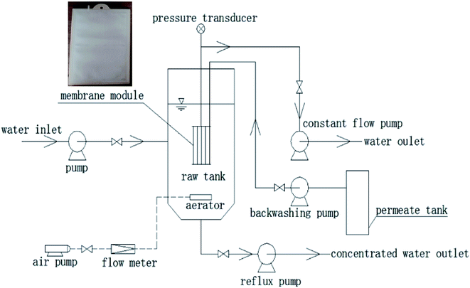
The flat membrane module used in this study is shown in Fig. 1, and its characteristics are listed in Table 1.| Parameter | Value |
|---|---|
| Texture of the membrane | PTFE |
| Texture of the support layer | Polyethylene terephthalate (PET) |
| Manufacturer | VALQUA Industries (Japan) |
| Average pore diameter (μm) | 0.1 |
| Effective length and width (cm) | 28 × 18 |
| Zeta potential (mV) | −22.1 |
| Contact angle (°) | 120.1 |
2.2. Experimental apparatus
The schematic of the experimental apparatus is shown in Fig. 1. It mainly consisted of a raw wastewater tank of volume 0.06125 m3, a membrane tank of volume 0.018 m3, an effluent tank, constant flow pumps, pressure transducers, and a data acquisition system. The flat membrane modules were vertically put in the membrane tank, which was installed inside the raw wastewater tank. The permeate was sucked from the raw wastewater tank by constant flow pumps (BT600-2J, Longer, China). The transmembrane pressure (TMP) was monitored by pressure transducers (PTP708, Tuopo Electric, Foshan, China), and the data were constantly recorded by a data acquisition software (Siemens).2.3. Composition of the raw wastewater
The raw wastewater was obtained from an oil production plant in Daqing, China, and its composition is shown in Table S1.† The raw wastewater contained a mass of anionic polyacrylamide (APAM) with the concentration of 749 ± 33 mg L−1, which was used as oil displacement. It also contained organic matter in large quantity, suspended solids (SS), and salts, with the concentrations of 1083 ± 65 mg L−1 of COD, 83 ± 17 mg L−1 of SS, and 5984 ± 450 mg L−1 of TDS, respectively, which might have caused serious fouling on the PTFE membrane. In addition, the pH and temperature of the raw wastewater were 12.6 ± 0.3 and 40 ± 0.7 °C, respectively.2.4. Membrane fouling and cleaning
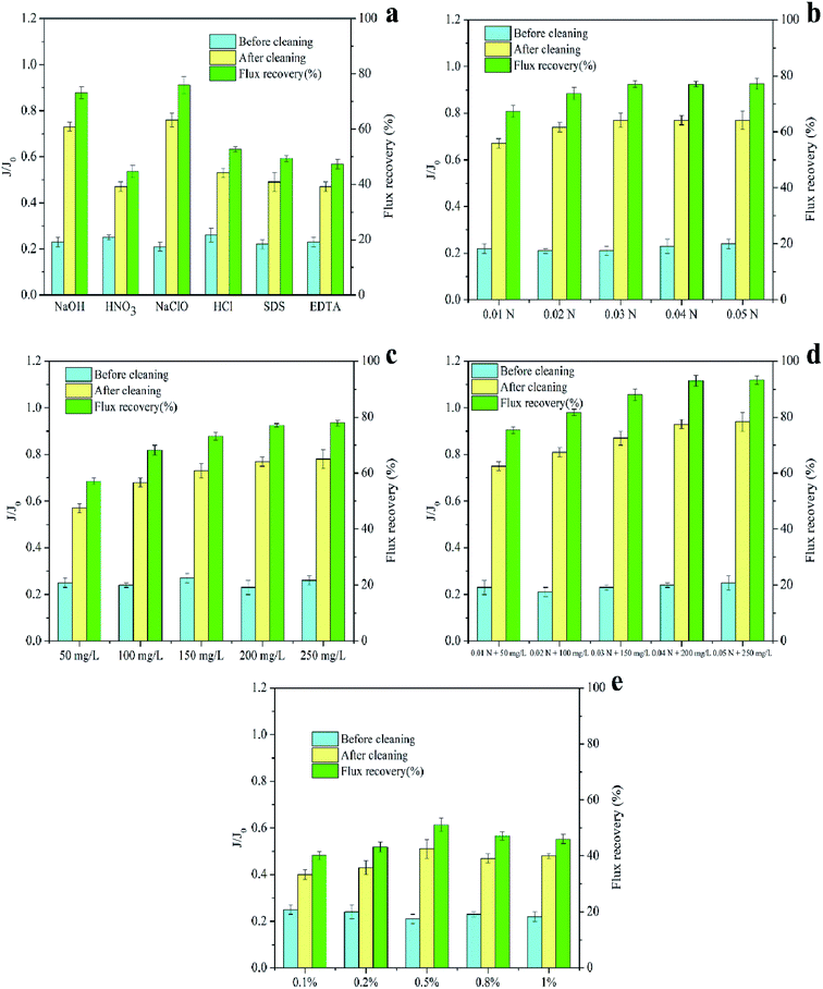
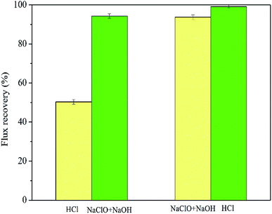
The operating parameters (operating flux, backwashing flux, and intensity of gas washing) of MF experiments were kept consistent to subject the membranes to the same degree of fouling. Additionally, MF processes were not terminated until the TMP reached a predetermined value (70 kPa). At the end of the experiments, NaOH, NaClO, HCl, HNO3, SDS, and EDTA solutions with a concentration of 0.5% (wt%) were used separately for immersion at 40 °C for 3 h to chemically clean the fouled PTFE membrane used for ASP flooding oilfield wastewater treatment. Based on preliminary screening, NaClO (0.01–0.05 N), NaOH (50–250 mg L−1), and HCl (0.1–1%) were selected as chemical cleaners for follow-up studies. Furthermore, the effects of cleaning sequence (NaClO + NaOH–HCl or HCl–NaClO + NaOH), temperature (20–50 °C), and time (0.5–5 h) on the cleaning efficiencies were also investigated. After each cleaning cycle, deionized water was filtered again to determine the flux recovery (FR); the calculation process used is shown in eqn (1).
 | (1) |
2.5. Analytical methods
The micromorphology of the membrane surface was observed and photographed by scanning electron microscopy (SEM, S-4800, Hitachi, Japan), and the main metal and non-metal elements on the fouled layer of the membrane surface were qualitatively evaluated using the energy dispersive X-ray spectrometer (EDX) on SEM. To retain the spatial morphology of the membrane to the maximum extent possible, the membranes were dried to a freezing state. Before observing the membrane sample, a conductive layer of gold, of approximately 2 nm thickness, was plated on the membrane surface by sputtering (Gatan, USA).1The functional groups on PTFE membranes were observed by Fourier transform infrared spectroscopy (FTIR, Nicolet 560, Thermo Electron Corp., USA), and the measured wavenumber range was 4000–650 cm−1.34
3. Results and discussion
3.1. Foulant analyses
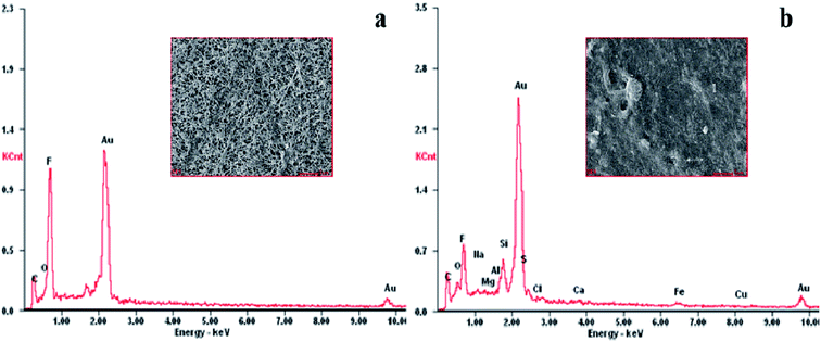
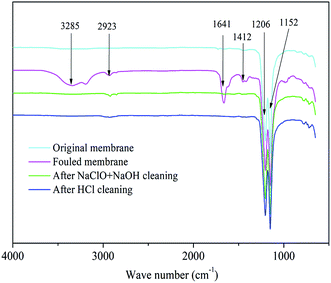
EDX scanning was performed on the surface of PTFE membranes, as shown in Fig. 2. The mass percentages of the elements found on the membranes are listed in Table S2.† C, O, and F were found to be the basic elements of the PTFE membrane, of which C and F came from the framework of the membrane and O belonged to the hydrophilic groups. The contents of C and O on the fouled membrane compared to that for the original membrane were observed to increase from 36.35% to 42.60% and 8.42% to 11.51%, respectively; the content of F significantly decreased from 55.23% to 21.36%. This indicated that the PTFE membrane was covered by many organic foulants, which may be crude oil, APAM, and surfactants contained in the raw wastewater. Furthermore, many inorganic elements appeared on the fouled membrane. The APAM molecules in the wastewater are negatively charged due to their ionized carboxyl groups. Therefore, positively charged metal ions can bind to the APAM molecules via electrostatic attraction and complexation bridging.35 Another possibility is that the alkalinity of ASP flooding oilfield wastewater was relatively high because it contained a large amount of OH− ions, which might have resulted in the formation of inorganic precipitates, such as Fe(OH)3, Ca(OH)2, and Mg(OH)2.The FTIR spectra of the PTFE membranes are represented in Fig. 3. The infrared absorption spectra of the fouled membrane show several new absorption peaks compared to that of the original membrane, where the peak at 3285 cm−1 represents the N–H bond of amide species, revealing that APAM assembled on the membrane surface.1 Furthermore, the observed absorption peaks of the C–H bond of alkanes, C![[double bond, length as m-dash]](https://www.rsc.org/images/entities/char_e001.gif) C bond of olefins, and methylene groups appeared at 2923 cm−1, 1641 cm−1, and 1412 cm−1, respectively, suggesting the presence of crude oil on the fouled membrane.36 The results obtained here were consistent with those of EDX analyses, implying that APAM and crude oil were the main membrane foulants.
C bond of olefins, and methylene groups appeared at 2923 cm−1, 1641 cm−1, and 1412 cm−1, respectively, suggesting the presence of crude oil on the fouled membrane.36 The results obtained here were consistent with those of EDX analyses, implying that APAM and crude oil were the main membrane foulants.
3.2. Comparison of the cleaning efficiencies among different reagents
The membrane fouling of the PTFE membranes used for ASP flooding oilfield wastewater treatment involves a combination of organic and inorganic species with regards to the type of foulants. Moreover, the foulants and the membranes are closely bound by complexation and hydrogen bonding. On-line physical cleaning (backwashing, aeration, etc.) is found to be difficult to completely restore the membrane performance; therefore, chemical cleaning with acids, bases, surfactants, metal chelators, and oxidants is required to remove the foulants that are difficult to wipe off the membrane surface.Furthermore, the NaClO solution exhibited a better cleaning performance compared to the NaOH solution, which was consistent with the results reported by Ahmad et al.39 and Zhang et al.40 Zhen et al.41 adopted NaOH, SDS, EDTA, HCl, citric acid, and oxalic acid to chemically clean the ultrafiltration membrane treated with oilfield produced water, and the results indicated that NaOH exhibited the best cleaning efficiency. Since the cleaning efficiency of the NaClO solution was not studied, no direct comparison can be drawn with the results of this experiment. Additionally, Wei et al.42 and Grélot et al.43 confirmed that NaClO exhibited the best results for flux recovery among all tested cleaning agents (e.g., NaOH, HCl, citric acid, and EDTA). Furthermore, the cleaning efficiency of alkalis was found to be better than that of acids since the membrane foulants were mainly organic, which was consistent with the results by Norazman et al.44
It was also observed that individual cleaning reagents could not completely remove all membrane foulants; thus, they could not achieve efficient cleaning. Therefore, NaClO, NaOH, and HCl solutions with better cleaning effects were selected as the chemical cleaning reagents in the following study. They were mixed for the consecutive cleaning of fouled membranes to obtain higher flux recovery and regeneration of the fouled membranes.
 | (2) |
 | (3) |
 | (4) |
 | (5) |
 | (6) |
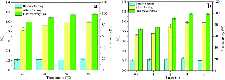
3.3. Cleaning efficiencies under different conditions
The flux recovery is not only affected by the type and the concentration of the cleaning reagent, but is also restricted by the cleaning conditions, such as the sequence, temperature, and time.28 Therefore, this section focuses on the effect of different cleaning conditions on flux recoveries.The flux recoveries were found to be 73.16%, 76.23%, 90.98%, 98.47%, and 98.24% at the cleaning times of 0.5 h, 1 h, 2 h, 3 h, and 5 h, respectively, indicating that the cleaning efficiencies improved with an extension in cleaning time. However, little difference was noted in the cleaning efficiencies at the cleaning times of 3 h and 5 h. This was because the prolonged cleaning time could only remove the foulants loosely bound to the membrane during the cleaning process and could not elute the foulants tightly adsorbed on the membrane.21 Furthermore, much longer immersion of the membrane in chemical cleaning reagents showed a definite impact on its properties and structure, and shortening the cleaning time helped in extending its lifespan. Thus, setting the cleaning time to 3 h was proven to be more appropriate.
3.4. Proposed mechanism of chemical cleaning
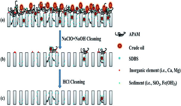 | ||
| Fig. 9 Schematic of the proposed mechanism of chemical cleaning of the PTFE membrane for ASP flooding oilfield wastewater treatment. | ||
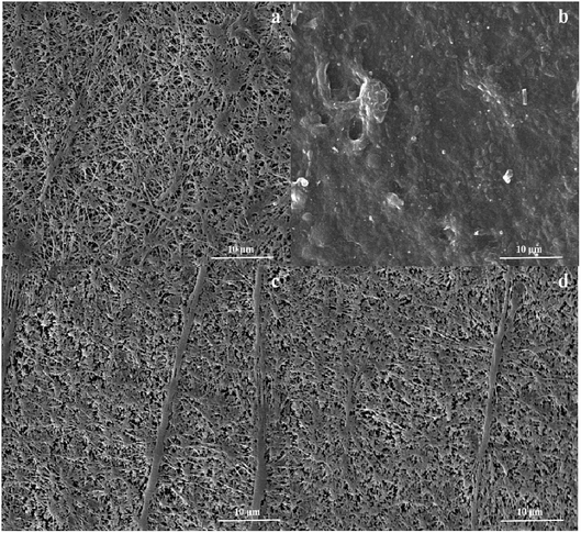
The microscopic analyses of the PTFE membranes (Fig. 3 and 7) revealed that consecutive cleaning with NaClO + NaOH–HCl could effectively remove foulants from the PTFE membrane. During the NaClO + NaOH cleaning process, NaOH, primarily as a bulking agent and protein solubilizer, first attacked the outermost membrane fouling layer. Afterwards, NaClO reacted more easily with the innermost APAM. The crude oil, SDBS, and encapsulated inorganic precipitate on the APAM fouling layer were separated from the membrane as the inner layer of APAM disintegrated (Fig. 9b). The residual inorganic elements due to bridging were removed by HCl cleaning. Afterwards, the organic foulants connected with them fell off from the membrane (Fig. 9c).
4. Conclusion
In this study, foulant analyses, cleaning efficiencies of different reagents and conditions and mechanisms during MF of ASP flooding oilfield wastewater were studied. The following conclusions were drawn from the study:(1) APAM and crude oil were the main membrane foulants accompanied by organic–inorganic–organic/membrane aggregate foulants formed by the bridging of inorganic ions.
(2) A cleaning efficiency of 93% was acquired through mixed cleaning with 0.04 N NaClO + 200 mg L−1 NaOH, which was found to be better than individual cleaning. Moreover, consecutive cleaning with NaClO + NaOH–HCl restored 98% of the membrane flux. Additionally, the cleaning temperature and time were set to 40 °C and 3 h, respectively.
(3) SEM-EDX and FTIR analyses displayed that NaClO + NaOH–HCl consecutive cleaning could effectively remove foulants from the membrane and restore membrane flux.
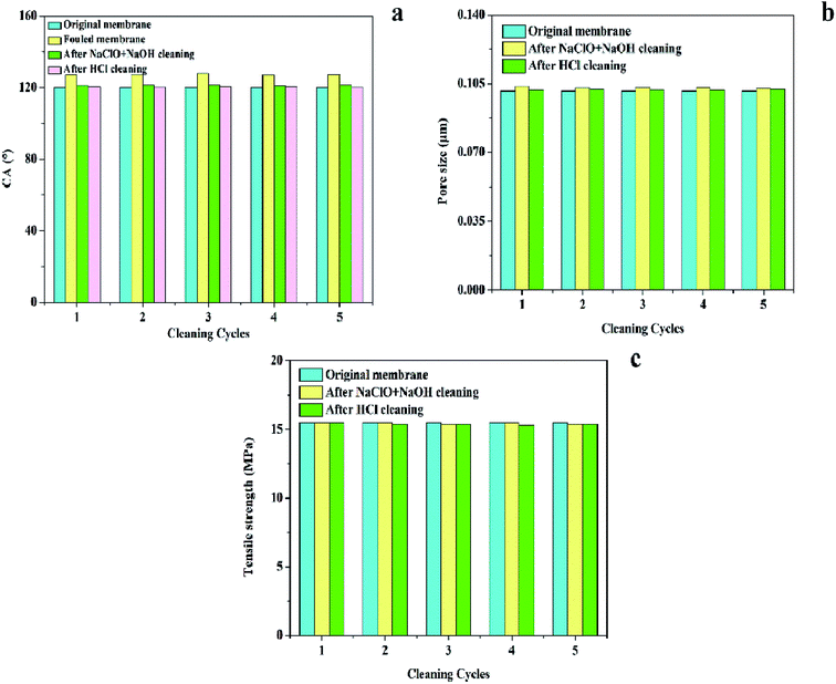
(4) The properties (CA, pore size, and tensile strength) of the cleaned membrane were not significantly different from that of the original membrane, which illustrated that the chemical properties of the PTFE membranes were relatively stable; also, consecutive cleaning using NaClO + NaOH–HCl was feasible.
Conflicts of interest
There are no conflicts to declare.Acknowledgements
This work was supported by the National Key Research and Development Program of China (2016YFE0205600), National Natural Science Foundation of China (Grant No. 51778172), and the Innovation Group of New Technologies for Industrial Pollution Control of Chongqing Education Commission (CXQT19023).Notes and references
- B. Zhang, W. Shi, S. Yu, Y. Zhu, R. Zhang and J. Hwa Tay, J. Colloid Interface Sci., 2019, 544, 303–311 CrossRef CAS PubMed.
- Y. Zhu, S. Yu, B. Zhang, J. Li, D. Zhao, Z. Gu, C. Gong and G. Liu, Sci. Total Environ., 2018, 642, 988–998 CrossRef CAS PubMed.
- B. Zhang, S. Yu, Y. Zhu, W. Shi, R. Zhang and L. Li, RSC Adv., 2016, 6, 62411–62419 RSC.
- A. Fakhru'l-Razi, A. Pendashteh, L. C. Abdullah, D. R. A. Biak, S. S. Madaeni and Z. Z. Abidin, J. Hazard. Mater., 2009, 170, 530–551 CrossRef PubMed.
- J. M. Dickhout, J. Moreno, P. M. Biesheuvel, L. Boels, R. G. H. Lammertink and W. M. de Vos, J. Colloid Interface Sci., 2017, 487, 523–534 CrossRef CAS PubMed.
- Y. Zhang, Y. Xu, S. Zhang, Y. Zhang and Z. Xu, Desalination, 2012, 299, 63–69 CrossRef CAS.
- C. Li, H. Zhang, F. Wang, H. Zhu, Y. Guo and M. Chen, RSC Adv., 2019, 9, 19205–19216 RSC.
- L. Ren, S. Yu, J. Li and L. Li, RSC Adv., 2019, 9, 11111–11122 RSC.
- D. Wu, W. Zhou, X. Cheng, C. Luo, P. Li, F. Zhang and Z. Ren, RSC Adv., 2019, 9, 20035–20043 RSC.
- A. Lin, S. Shao, H. Li, D. Yang and Y. Kong, J. Membr. Sci., 2011, 371, 286–292 CrossRef CAS.
- S.-C. Chen, S.-H. Lin, R.-D. Chien and P.-S. Hsu, J. Hazard. Mater., 2010, 179, 692–700 CrossRef CAS PubMed.
- B. Zhang, S. Yu, Y. Zhu, Y. Shen, X. Gao, W. Shi and J. Hwa Tay, Sep. Purif. Technol., 2019, 116212 Search PubMed.
- X. Sun, D. M. Kanani and R. Ghosh, J. Membr. Sci., 2008, 320, 372–380 CrossRef CAS.
- M. Peydayesh, T. Mohammadi and O. Bakhtiari, Sep. Purif. Technol., 2018, 194, 488–502 CrossRef CAS.
- S. Wang, K. Xiao and X. Huang, Sep. Purif. Technol., 2019, 210, 1008–1016 CrossRef CAS.
- Y. Chung, H. Kim, T.-S. Kim, Y. M. Kim and S. Kang, Sep. Purif. Technol., 2019, 219, 216–221 CrossRef CAS.
- W. Li, G. Ling, F. Lei, N. Li, W. Peng, K. Li, H. Lu, F. Hang and Y. Zhang, Sep. Purif. Technol., 2018, 190, 9–24 CrossRef CAS.
- J. Liu, K. He, S. Tang, T. Wang and Z. Zhang, Sep. Purif. Technol., 2019, 217, 118–127 CrossRef CAS.
- D. Zhao, L. Qiu, J. Song, J. Liu, Z. Wang, Y. Zhu and G. Liu, Sci. Total Environ., 2019, 652, 256–266 CrossRef PubMed.
- G. Liu, L. Li, L. Qiu, S. Yu, P. Liu, Y. Zhu, J. Hu, Z. Liu, D. Zhao and H. Yang, J. Membr. Sci., 2018, 545, 348–357 CrossRef CAS.
- B. Zhang, W. Shi, S. Yu, Y. Zhu, R. Zhang and L. Li, RSC Adv., 2015, 5, 104960–104971 RSC.
- J. Lindau and A.-S. Jönsson, J. Membr. Sci., 1994, 87, 71–78 CrossRef CAS.
- Y. Zhao, L. Hou and S. Yu, China Water & Wastewater, 2013, 29, 134–137 Search PubMed.
- Y. Song, B. Su, X. Gao and C. Gao, Desalination, 2013, 330, 61–69 CrossRef CAS.
- M. S. Manna, P. Saha and A. K. Ghoshal, RSC Adv., 2015, 5, 71999–72008 RSC.
- Q. Li and M. Elimelech, Environ. Sci. Technol., 2004, 38, 4683–4693 CrossRef CAS PubMed.
- P. D. I. Fletcher, L. D. Savory, F. Woods, A. Clarke and A. M. Howe, Langmuir, 2015, 31, 3076–3085 CrossRef CAS PubMed.
- Z. Wang, J. Ma, C. Y. Tang, K. Kimura, Q. Wang and X. Han, J. Membr. Sci., 2014, 468, 276–307 CrossRef CAS.
- M. T. Khan, C.-L. d. O. Manes, C. Aubry and J.-P. Croué, Water Res., 2013, 47, 558–568 CrossRef CAS PubMed.
- M. T. Khan, M. Busch, V. G. Molina, A.-H. Emwas, C. Aubry and J.-P. Croue, Water Res., 2014, 59, 271–282 CrossRef CAS PubMed.
- M. Mouiya, A. Abourriche, A. Bouazizi, A. Benhammou, Y. El Hafiane, Y. Abouliatim, L. Nibou, M. Oumam, M. Ouammou, A. Smith and H. Hannache, Desalination, 2018, 427, 42–50 CrossRef CAS.
- M. M. Bazin, Y. Nakamura and N. Ahmad, J. Teknol., 2018, 80, 95–103 Search PubMed.
- H. Sun, H. Liu, S. Wang, F. Cheng and Y. Liu, Water Res., 2018, 146, 328–336 CrossRef CAS PubMed.
- J. Zhu, M. Tian, Y. Zhang, H. Zhang and J. Liu, Chem. Eng. J., 2015, 265, 184–193 CrossRef CAS.
- R. Zhang, W. Shi, S. Yu, W. Wang, Z. Zhang, B. Zhang, L. Li and X. Bao, Desalination, 2015, 373, 27–37 CrossRef CAS.
- H. Maekawa, G. Ballano, C. Toniolo and N.-H. Ge, J. Phys. Chem. B, 2011, 115, 5168–5182 CrossRef CAS PubMed.
- Y. C. Woo, J. J. Lee, L. D. Tijing, H. K. Shon, M. Yao and H.-S. Kim, Desalination, 2015, 369, 51–61 CrossRef CAS.
- Z. Zhang, M. W. Bligh, Y. Wang, G. L. Leslie, H. Bustamante and T. D. Waite, J. Membr. Sci., 2015, 475, 9–21 CrossRef CAS.
- A. L. Ahmad, N. H. Mat Yasin, C. J. C. Derek and J. K. Lim, J. Taiwan Inst. Chem. Eng., 2014, 45, 233–241 CrossRef CAS.
- X. Zhang, Q. Hu, M. Sommerfeld, E. Puruhito and Y. Chen, Bioresour. Technol., 2010, 101, 5297–5304 CrossRef CAS PubMed.
- X. Zhen, S. Yu, B. Wang and C. Liang, Water Wastewater Eng. Chinese, 2006, 32, 56–59 Search PubMed.
- C.-H. Wei, X. Huang, R. Ben Aim, K. Yamamoto and G. Amy, Water Res., 2011, 45, 863–871 CrossRef CAS.
- A. Grélot, C. Machinal, K. Drouet, A. Tazi-Pain, J. C. Schrotter, A. Grasmick and S. Grinwis, Water Sci. Technol., 2008, 58, 2041–2049 CrossRef.
- N. Norazman, W. Wu, H. Li, V. Wasinger, H. Zhang and V. Chen, Sep. Purif. Technol., 2013, 103, 241–250 CrossRef CAS.
- A. L. Ahmad, N. H. Mat Yasin, C. J. C. Derek and J. K. Lim, Desalination, 2012, 302, 65–70 CrossRef CAS.
- A. El Achari, X. Coqueret, A. Lablache-Combier and C. Loucheux, Macromol. Chem., 1993, 194, 1879–1891 CrossRef CAS.
- C. Liu, S. Caothien, J. Hayes, T. Caothuy, T. Otoyo and T. Ogawa, in Proc. AWWA Water Qual. Technol. Conf., Denver Co., 2000, pp. 1–25 Search PubMed.
- M. D. Kennedy, J. Kamanyi, S. G. S. Rodríguez, N. H. Lee, J. C. Schippers and G. Amy, Adv. Membr. Technol. Appl., 2008, 131–170 CrossRef CAS.
- A. Al-Amoudi and R. W. Lovitt, J. Membr. Sci., 2007, 303, 4–28 CrossRef CAS.
- H. Liang, W. Gong, J. Chen and G. Li, Desalination, 2008, 220, 267–272 CrossRef CAS.
- X. Wang and T. D. Waite, Environ. Sci. Technol., 2009, 43, 9341–9347 CrossRef CAS PubMed.
- K. Xiao, Y. Shen and X. Huang, J. Membr. Sci., 2013, 427, 139–149 CrossRef CAS.
- L.-F. Wang, D.-Q. He, W. Chen and H.-Q. Yu, Water Res., 2015, 81, 325–332 CrossRef CAS PubMed.
- S. S. Madaeni and S. Samieirad, Desalination, 2010, 257, 80–86 CrossRef CAS.
- G. J. Zhang, Z. Z. Liu, L. F. Song, J. Y. Hu, S. L. Ong and W. J. Ng, Desalination, 2004, 170, 271–280 CrossRef CAS.
- M. Bartlett, M. R. Bird and J. A. Howell, J. Membr. Sci., 1995, 105, 147–157 CrossRef CAS.
- S. H. D. Silalahi and T. Leiknes, Desalination, 2009, 236, 160–169 CrossRef CAS.
- G. Liu, S. Yu, H. Yang, J. Hu, Y. Zhang, B. He, L. Li and Z. Liu, Environ. Sci. Technol., 2016, 50, 1393–1402 CrossRef CAS PubMed.
Footnote |
| † Electronic supplementary information (ESI) available. See DOI: 10.1039/c9ra06745k |
| This journal is © The Royal Society of Chemistry 2019 |

