 Open Access Article
Formation of toroidal Li2O2 in non-aqueous Li–O2 batteries with Mo2CTx MXene/CNT composite†
Mihye Wuab,
Do Youb Kim bd,
Hyunsoo Parka,
Kyeong Min Cho
 a,
Ju Ye Kima,
Seon Joon Kimc,
Sungho Choi
 b,
Yongku Kangbd,
Jihan Kim
 *a and
Hee-Tae Jung
 *a
*a
aDepartment of Chemical and Biomolecular Engineering (BK-21 Plus), KAIST Institute for Nanocentury, Korea Advanced Institute of Science and Technology, 291 Daehak-ro, Yuseong-gu, Daejeon 34141, Republic of Korea. E-mail: Jihankim@kaist.ac.kr; heetae@kaist.ac.kr; Fax: +82-42-350-3910; Fax: +82-42-350-8452; Tel: +82-42-350-7311 Tel: +82-42-350-3931
bAdvanced Materials Division, Korea Research Institute of Chemical Technology, Yuseong-gu, Daejeon 34114, Korea
cMaterials Architecturing Research Center, Korea Institute of Science and Technology (KIST), Seoul 02792, Republic of Korea
dDepartment of Chemical Convergence Materials, Korea University of Science and Technology (UST), Yuseong-gu, Dajeon 34113, Korea
First published on 16th December 2019
Abstract
Due to the growing demand for high energy density devices, Li–O2 batteries are considered as a next generation energy storage system. The battery performance is highly dependent on the Li2O2 morphology, which arises from formation pathways such as the surface growth and the solution growth models. Thus, controlling the formation pathway is important in designing cathode materials. Herein for the first time, we controlled the Li2O2 formation pathway by using Mo2CTx MXene on a catalyst support. The cathode was fabricated by mixing the positively charged CNT/CTAB solution with the negatively charged Mo2CTx solution. After introducing Mo2CTx, important battery performance metrics were considerably enhanced. More importantly, the discharge product analysis showed that the functional groups on the surface of Mo2CTx inhibit the adsorption of O2 on the cathode surface, resulting in the formation of toroidal Li2O2 via the solution growth model. It was supported by density functional theory (DFT) calculations that adsorption of O2 on the Mo2CTx surface is implausible due to the large energy penalty for the O2 adsorption. Therefore, the introduction of MXene with abundant functional groups to the cathode surface can provide a cathode design strategy and can be considered as a universal method in generating toroidal Li2O2 morphology.
Introduction
Li–O2 batteries have been considered to be a promising candidate for high energy density energy storage systems due to their extremely high energy density (∼3500 W h kg−1), which is far higher than that of current Li-ion batteries.1 The typical redox reaction mechanism of the Li–O2 battery is the formation and decomposition of lithium peroxide (Li2O2); during discharge, an oxygen reduction reaction (ORR) occurs on the surface of the cathode electrode to produce Li2O2 as a discharge product, and during charge, electrochemical decomposition of the produced Li2O2 into Li+ and O2 occurs, that is oxygen evolution reaction (OER).2Recent studies revealed that comprehension of electrochemistry and the chemistry behind the Li2O2 formation are crucial in determining the Li–O2 battery performances.4 Specifically, there are two Li2O2 formation models: (i) surface growth model and (ii) solution growth model.4 In the surface growth model, since the nucleation of Li2O2 occurs on the surface of the cathode, the morphology of the deposited Li2O2 is a thin film type, resulting in small discharge capacity due to the small amount of produced Li2O2 but low OER overpotential due to the close contact of the thin film. In the solution growth model, since the nucleation of Li2O2 occurs in the solution via the disproportionation reaction of the soluble LiO2 intermediate, the resultant morphology of Li2O2 is a toroidal structure, which leads to high discharge capacity due to the large amount of produced Li2O2 but a high OER overpotential due to the large particle size of toroidal Li2O2.4 Thus, the formation of Li2O2 highly influences the electrochemical properties of the Li–O2 batteries.
One of the most effective strategies in controlling and changing Li2O2 formation pathway is selecting cathode materials with different O2 adsorbability. It is highly suggested that thin film type Li2O2 morphology can be obtained by using a cathode with high O2 affinity (e.g. Co3O4 and Mo2C) via the surface growth model. On the other hand, it is recommended that toroidal Li2O2 can be achieved by using the cathode with low O2 affinity via the solution growth model.5
Here, we used MXene for the first time to control the O2 adsorbability of the cathode, which is attributed to the surface functional groups with high coverage. MXenes are a new family of two-dimensional (2D) transition metal carbides,6 and considered to be one of the most promising materials for energy storage systems due to their high electrical conductivity, rapid diffusion of ions and molecules, high specific surface area, and hydrophilic surfaces.7 The general formula of MXene is Mn+1XnTx (n = 1–3), where M stands for transition metals, X stands for nitrogen or/and carbon, and consequently, there are diverse compositions of MXenes (e.g. Ti3C2Tx, Ti2CTx, Zr3C2Tx, Sc4N3Tx, and Nb4C3Tx) with Tx representing the surface termination groups (e.g. oxygen, hydroxyl and fluorine), which fully cover the outer surface.8 In general, preparing materials with high surface coverage is challenging because it is difficult to introduce surface functionality in significantly high concentrations. However, MXenes are covered by surface termination groups with extraordinarily high surface coverage,9 which is responsible for its uniqueness. We found that MXene plays an important role in determining Li2O2 formation pathway in non-aqueous Li–O2 batteries.
Experimental
Preparation of Mo2CTx
Mo2CTx was prepared by the method previously reported elsewhere.10 Mo2CTx was synthesized by selective etching of gallium (Ga, Kojundo Korea, 99.99%) atoms from Mo2Ga2C using concentrated hydrofluoric acid (HF, Junsei, 40%). Mo2Ga2C was prepared by a solid–liquid reaction between Mo2C and Ga, in a molar ratio of 1![[thin space (1/6-em)]](https://www.rsc.org/images/entities/char_2009.gif) :
:![[thin space (1/6-em)]](https://www.rsc.org/images/entities/char_2009.gif) 8. The mixture was annealed at 850 °C for 16 hours in a vacuum furnace and cooled down to room temperature, followed by re-annealing at 850 °C for 48 hours to form Mo2Ga2C. Then, 2 g of Mo2Ga2C was placed in a polypropylene (PP) beaker with 40 ml of concentrated HF and stirred for 6 days to remove Ga atoms. The resultant powder was washed with 1 M hydrochloric acid (HCl, Daejung, 35%) and de-ionized water for several cycles until the pH of ≈ 7 was reached. To obtain delaminated Mo2CTx, 1 g of the powder was immersed in 10 ml of tetrabutylammonium hydroxide (TBAOH, Sigma-Aldrich, 57%) for 4 hours, then washed with DI water. 250 ml of DI water was added to the TBAOH-treated powder, and sonicated in an ice bath for 1 hour using a dismembrator. Then 40 ml of the above suspension was transferred to each centrifuge tube, and was centrifuged at 25
8. The mixture was annealed at 850 °C for 16 hours in a vacuum furnace and cooled down to room temperature, followed by re-annealing at 850 °C for 48 hours to form Mo2Ga2C. Then, 2 g of Mo2Ga2C was placed in a polypropylene (PP) beaker with 40 ml of concentrated HF and stirred for 6 days to remove Ga atoms. The resultant powder was washed with 1 M hydrochloric acid (HCl, Daejung, 35%) and de-ionized water for several cycles until the pH of ≈ 7 was reached. To obtain delaminated Mo2CTx, 1 g of the powder was immersed in 10 ml of tetrabutylammonium hydroxide (TBAOH, Sigma-Aldrich, 57%) for 4 hours, then washed with DI water. 250 ml of DI water was added to the TBAOH-treated powder, and sonicated in an ice bath for 1 hour using a dismembrator. Then 40 ml of the above suspension was transferred to each centrifuge tube, and was centrifuged at 25![[thin space (1/6-em)]](https://www.rsc.org/images/entities/char_2009.gif) 000 rpm for 5 min. The resultant supernatant was collected whereas the settled powder was removed.
000 rpm for 5 min. The resultant supernatant was collected whereas the settled powder was removed.
Preparation of CNT/Mo2CTx
50 mg of carbon nanotube (CNT) was dispersed in 100 ml of DI water with cetyltrimethylammonium bromide (CTAB, Sigma-Aldrich) to produce a 0.5 mg ml−1 solution. 140 ml of DI water was added to 14 ml of CNT solution to produce a dilute CNT solution, and was added dropwise into the delaminated Mo2CTx, obtaining a weight ratio between CNT and Mo2CTx of 7 to 3, and it was then stirred for 1 hour. Then polystyrene bead (PS, Sigma-Aldrich, 10 wt%) was added to the above suspension to obtain the weight ratio between CNT/Mo2CTx to polystyrene bead as 1 to 10, and it was then sonicated for 30 min. The resultant suspension was vacuum filtrated with a membrane filter (Durapore, 0.22 μm GV), and dried at 80 °C for 12 hours. The resultant electrode was peeled off from the membrane filter, and then annealed at 450 °C for 2 hours under Ar to remove PS beads.To clarify the effect of MXene, the CNT electrode was fabricated by the same procedure with 20 ml of CNT solution but without Mo2CTx.
Measurements
The surface and cross-sectional view of the CNT and CNT/Mo2CTx electrodes were characterized by using scanning electron microscopy (SEM, Tescan Mira 3 LMU FEG, 20 kV). The surface functional groups were identified by X-ray photoelectron spectroscopy (XPS, Thermo VG Scientific). The crystal structure of the discharged product was confirmed by X-ray powder diffractometer (XRD, Rigaku ultima IV Diffractometer) with graphite-monochromator equipped with Cu Kα line (40 kV/40 mA). The Brunauer–Emmett–Teller (BET) surface area was measured by nitrogen adsorption/desorption at 77.3 K.The CNT and CNT/Mo2CTx electrodes served as the cathode, which were dried at 120 °C for 12 hours under vacuum, then assembled in an argon-filled glove box using Swagelok type cells. The average mass loading of the electrode was about 0.65 mg and the size was 12 mm in diameter.
The electrolyte was 1 M lithium nitrate (LiNO3, Sigma-Aldrich) in dimethylacetamide (DMAc, Sigma-Aldrich) with water concentration <30 ppm determined by a Mettler-Toledo Karl Fischer titration. Li foil served as the anode.
Electrochemical performances were tested with a battery cycler (WBCS-3000, WonAtech) at an applied current density of 200 mA gCNT−1 for 5 hours and 100 mA gCNT−1 with 2.0 V cut-off, respectively, for cycle life and specific capacity measurements.
Calculations
All of the first-principle calculations were performed with the Vienna Ab Initio Simulation Package (VASP)18 with the projector augmented wave (PAW)19 potentials. In order to calculated the adsorption energy of O2 on the surface of β-Mo2C, the Perdue–Burke–Ernzerhof (PBE)20 along with the dispersion force for van de Waals interactions (PBE-D3)21 was utilized for exchange–correlation functional. The geometry optimizations were conducted with a maximum force criterion of 0.005 eV Å−1, energy criterion of 10−6 eV per cell and cutoff energy of 520 eV. The initial unit-cells of β-Mo2C and Mo2C(OH)2 were set with a vacuum space of 30 Å along the vertical direction of single layer of MXene with a Γ-centered 12 × 12 × 1 k-mesh. The (3 × 3) slabs were utilized for calculating the O2 adsorption energy with a Γ-centered 4 × 4 × 1 k-mesh. The vibrational frequency analysis are obtained by PHONOPY22 code. The force constants matrix was constructed by 4 × 4 × 1 supercell with density functional perturbation theory.23Results and discussion
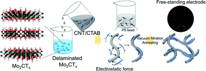
The schematic for fabricating the CNT/Mo2CTx cathode is described in Fig. 1. We selected carbon nanotubes (CNTs) as a catalyst support due to their excellent electrical conductivity, high mechanical strength, and facile fabrication into binder-free cathode.11 Moreover, they provide a porous structure for better O2 diffusion and Li2O2 accommodation. It is noteworthy that Mo2CTx was used as a catalyst simply because of its good catalytic activity in catalysis field12 as well as easy fabrication.10Since CNT was dispersed with a cationic surfactant cetyltrimethylammonium bromide (CTAB), the surface of the CNTs were positively charged; whereas the surface functional groups including –O and –OH result in the negatively charged MXene surfaces. The positively charged CNT solution was added to the negatively charged Mo2CTx solution to obtain uniformly attached Mo2CTx on the surface of CNTs in a weight ratio of 3 to 7, by the electrostatic force.13 The PS beads were added to the mixed solution, then the resultant solution was vacuum filtered to fabricate paper type electrode. The electrode was annealed at 450 °C to create micron-sized pores in the electrode by PS removal.
SEM image shows that CNTs are well distributed over the paper type electrode with porous structure and possess well-connected networks (Fig. 2a). After introducing MXene catalyst to the CNTs, there are small Mo2CTx particles deposited on the CNTs (see the arrows of Fig. 2b), which were confirmed by EDS mapping in Fig. S1,† in maintaining pristine CNT morphology. Inset images of Fig. 2a and b exhibit the cross-sectional views of CNT and CNT/Mo2CTx electrodes, respectively, to clarify the formation of macropores after PS calcination. It has been reported that introducing pores in the paper type electrode can improve the cycle life by preventing irreversible volume expansion of the electrode, which is attributed to the growth of Li2O2 particles inside the paper electrode.17 In this regard, the macropores were introduced to CNT and CNT/Mo2CTx electrodes to accommodate the discharge products. After PS removal, both electrodes showed highly porous structure with an average pore size of 2 μm, and the well-connected conductive networks were still maintained through the whole electrodes.
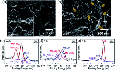 | ||
| Fig. 2 SEM images of (a) CNT (top-view), (b) CNT/Mo2CTx (top-view) electrodes. Inset images for cross-sectional view. CNT/Mo2CTx (c) Mo 3d, (d) O 1s, and (e) C 1s spectra. | ||
To verify the surface functionality of CNT/Mo2CTx electrode, X-ray photoelectron spectroscopy (XPS) measurements were conducted and the results are shown in Fig. 2c–e. The Mo 3d spectrum is composed of Mo–C, Mo4+, and Mo6+. The binding energy at 227.95 eV and 232 eV are assigned to the Mo–C (3d5/2) and Mo–C (3d2/3) species from CNT/Mo2CTx.10 The O 1s spectrum is composed of species corresponding to the Mo-oxide, Mo2COx, Mo2C(OH)x, and Mo2C(OH)x–H2O. The binding energy at 529.48 eV is assigned to the Mo-oxide, which is generated by surface oxidation.10 The peaks at 530.5 and 531.62 eV are assigned to the –O terminated Mo2COx and –OH terminated Mo2C(OH)x. The relatively small peak at 533.25 eV is assigned to Mo2C(OH)x–H2O.10 The C 1s spectrum is composed of components corresponding to the C![[double bond, length as m-dash]](https://www.rsc.org/images/entities/char_e001.gif) C, C–H, and O–C
C, C–H, and O–C![[double bond, length as m-dash]](https://www.rsc.org/images/entities/char_e001.gif) O at the binding energy of 283.81, 285.13 and 289.61 eV, respectively.14 Hence, the CNT/Mo2CTx electrode contains abundant functional groups including -oxide, –Ox, –(OH)x, and –(OH)x–H2O.
O at the binding energy of 283.81, 285.13 and 289.61 eV, respectively.14 Hence, the CNT/Mo2CTx electrode contains abundant functional groups including -oxide, –Ox, –(OH)x, and –(OH)x–H2O.
To investigate the effect of the Mo2CTx catalyst, the electrochemical performance of the CNT/Mo2CTx electrode was evaluated and compared with the CNT electrode. The as-prepared paper type electrodes were assembled into the Li–O2 cell and tested with constant current under limited capacity and limited voltage conditions. When the Li–O2 cell was discharge with the CNT electrode at 100 mA gCNT−1 in a 2.0 V cut-off condition, the capacity was 5950 mA h gCNT−1 (Fig. 3a). The discharge capacity of the CNT/Mo2CTx electrode was 9100 mA h gCNT−1, which is much higher than that of the CNT electrode. Because the surface area of the cathode is related to the discharge capacity, it is necessary to examine the surface area of the CNT and CNT/Mo2CTx electrode. The BET measurements were conducted on both electrodes and the results are presented in Table S1.† Although the surface area of the CNT/Mo2CTx is smaller than that of the CNT, the CNT/Mo2CTx showed much higher discharge capacity. Thus, the Mo2CTx introduction greatly improves discharge capacity by promoting the Li2O2 formation.
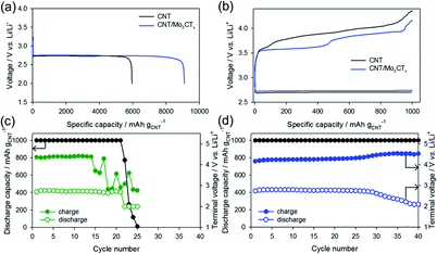 | ||
| Fig. 3 (a) Discharge capacity and (b) voltage profiles of CNT and CNT/Mo2CTx electrodes, cycle life of (c) CNT electrode and (d) CNT/Mo2CTx electrode. | ||
On the other hand, Li–O2 cells were cycled in a limited capacity of 1000 mA h gCNT−1 with a current density of 200 mA gCNT−1. The voltage profiles of the 1st cycle were shown in Fig. 3b that the OER overpotential was reduced by the Mo2CTx introduction to the electrode. Moreover, the CNT/Mo2CTx exhibited better cycling performance over 40 cycles than that of the CNT electrode (Fig. 3c and d). In this regard, the catalytic activity of Mo2CTx toward Li–O2 reactions were demonstrated and the Mo2CTx MXene can be considered as an effective catalyst for Li–O2 batteries.
In order to verify the Li2O2 formation pathway of the Mo2CTx incorporated cathode, the ex situ XRD and SEM were carried out. The CNT/Mo2CTx electrode was discharged until the voltage reaches at 2.0 V with constant current of 100 mA gCNT−1, and then the cell was dissembled to analyse the discharge product.
The ex situ XRD pattern in Fig. 4a exhibited that 2 theta values at 32.89, 34.97 and 58.72 degrees correspond to the (1 0 0), (1 0 1) and (1 1 0) planes were assigned to the typical Li2O2 (JCPDS#01-074-0115). Thus, the discharge product was demonstrated as Li2O2, the main product of Li–O2 reactions, which signifies that the prepared electrode obeys the fundamental principles of Li–O2 batteries.
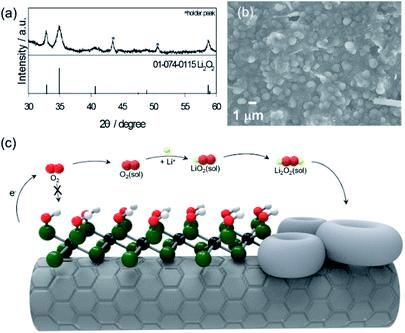 | ||
| Fig. 4 (a) Ex situ XRD, (b) SEM image of CNT/Mo2CTx electrode after discharge, (c) schematic of the Li2O2 formation for the CNT/Mo2CTx electrode. | ||
The SEM image of the discharge product (Li2O2) shows that the CNT/Mo2CTx electrode was almost covered with typical toroidal Li2O2 with a particle size of 1 μm (Fig. 4b). To clarify the effect of Mo2CTx on the toroidal Li2O2 formation, the CNT electrode was dissembled after discharge, then the SEM images were taken (Fig. S2†). Unlike the CNT/Mo2CTx electrode, the surface of the discharged CNT electrode was covered with thick deposits and sparse distribution of toroidal Li2O2. Thus, it is clear that this highly covered toroidal morphology is originated from the high surface coverage of MXene. The fully covered surface functional groups inhibit the access of O2 on the surface of Mo2C, preventing the adsorption of O2 on Mo. Consequently, this inaccessibility of O2 to the cathode surface hinders the nucleation of the intermediate (LiO2) on the cathode surface, which derives the solution growth model to undergo Li2O2 nucleation in the electrolyte, resulting in toroidal morphology.3 The schematic representation of the Li2O2 nucleation process with CNT/Mo2CTx electrode was illustrated in Fig. 4c.
It is noteworthy that non-functionalized molybdenum carbide (Mo2C without functional groups) has been previously reported to generate the thin film type Li2O2, which suggests the surface growth model for Li2O2 nucleation. The origin of this formation mechanism is supposed to be the lack of coordination vacancy of Mo, which leads to a strong affinity between O2 and Mo2C, resulting in the surface growth model of Li2O2. Kwak et al. reported the Mo2C/carbon nanotube composite with excellent Li–O2 battery performances, operated under 1 M LiCF5O3 in TEGDME at 100 mA g−1, attributed to the formation of MoO3-like layers on the Mo2C nanoparticles by chemisorption of O2 on the surface of Mo.15 The morphology of Li2O2 after discharge was confirmed as a well dispersed thin layer type. Zhu et al. developed carbon-wrapped Mo2C nanoparticles and CNTs on Ni foam as a cathode, operated under 1 M LiTFSI in TEGDME at 200 mA g−1, and the discharge product was uniformly coated on the surface of the CNTs.16 Since we used 1 M LiNO3 in DMAc as electrolyte, which is known as a strong solution growth facilitator, it is necessary to eliminate the electrolyte effect to clarify the role of Mo2CTx. In this regard, the CNT/Mo2CTx electrode was discharged at 100 mA g−1 in a 2.0 V cut-off condition under 1 M LiTFSI in TEGDME, which has low donor number, and the resultant discharge product was observed by SEM. As shown in Fig. S3b,† the surface of CNT/Mo2CTx electrode was covered by discharge product with nearly spherical-like morphology without any thin film formation. These results imply that the Mo2C catalyst-mediated Li2O2 nucleation is governed by the surface growth model.
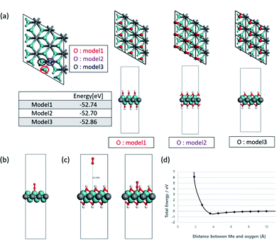
To understand the effect of the surface functional groups on the Li2O2 formation pathway, density functional theory (DFT) with PBE-D3 method. The hydroxyl group (–OH) was selected as the functional group because it is the least stable species so can desorb first.9 For the OH-terminated MXene (Mo2C(OH)2) in shown as Fig. 5a, there are three representative possible configurations (model 1: OH groups are located on the top of Mo metal; model 2: OH groups are located on the top of carbon in Mo2C(OH)2 single layer at the hollow sites; model 3: OH groups are located on the another hollow site which is position of Mo in bottom of Mo2C(OH)2 single layer). In order to calculate the O2 adsorption on the surface of Mo2C(OH)2, the most stable model 3 of Mo2C(OH)2 was selected by the vibrational frequency analysis and the energy of the geometry optimized structures when absorbing O2. The vibrational frequency analysis indicates that Mo2C(OH)2 have some imaginary frequencies, on the other hand, Mo2C have a no imaginary frequency in Fig. S4.† These tendencies are also found in α-Mo2C24 as well as β-Mo2C. Although Mo2C(OH)2 have dynamic instability from the analysis of phonon dispersion, model 3 is regarded as at least the most stable structure because model 3 have the lowest geometry optimized energy (−52.86 eV) and only one small imaginary frequency when comparing model 1 and 2 (each −52.74 and 52.70 eV).
As such, the OH-terminated MXene for model 3 was selected as the configuration to examine the binding energy of O2. The 3 × 3 slabs of Mo2C and Mo2C(OH)2 were utilized for the adsorption energy of O2. At first, non-terminated Mo2C surface was computed to be −272 kJ mol−1 (Fig. 5b), while that of Mo2C(OH)2 led to non-convergent result. As such, the position of all the atoms were fixed in the simulations to obtain the fixed single-point energies for varying O2 positions relative to the Mo2C(OH)2 surface (Fig. 5c). Specifically the O2 molecule was initialized at a distance 10 Å from top of the Mo metal with subsequent configurations coming closer to the top of the Mo metal from model 3. The resulting single point energy data (Fig. 5d) reveals that O2 cannot bind to the surface of Mo2C(OH)2, implying that LiO2 nucleation as well as Li2O2 cannot possibly occur on the surface of Mo2CTx surface. This is consistent with the experimental finding and corroborates that the toroidal Li2O2 formation pathway is resulted from the inaccessibility of O2 on the cathode surface.
Conclusions
We found that MXene with abundant functional groups not only enhanced the battery performance but also played a significant role in determining the Li2O2 formation pathway. The discharge capacity, overpotential and cycle life were improved by introducing Mo2CTx on CNTs, which manifest that the Mo2CTx exhibits good catalytic activity toward Li–O2 reactions. The high surface coverage of Mo2CTx with functional groups resulted in the toroidal Li2O2 formation via the solution growth model. This is attributed to the inaccessibility of O2 to the cathode surface, which was verified by the DFT calculations.It is noticeable that here we only studied one type of MXene, but more diverse MXenes can play a critical role in determining the Li2O2 formation pathway due to their extraordinarily high surface coverage. We believe this study will provide guidelines for a large family of MXenes to be considered as effective catalysts for the Li–O2 batteries in the future.
Conflicts of interest
There are no conflicts to declare.Acknowledgements
This research was supported by the Korea Research Institute of Chemical Technology (project No. KK1922-20) and the National Research Foundation of Korea (NRF) funded by the Ministry of Education, Science and Technology (MEST) (NRF-2015K1A4A3047100) and the National Research Foundation of Korea (NRF) grant funded by the Ministry of Science and ICT (MSIT) (2018R1A2B3008658) and Future Planning, Korea. This research was also supported in part by Energy Cloud R&D Program (NRF-2019M3F2A1072233) through NRF (National Research Foundation of Korea) funded by Ministry of Science and ICT.References
- P. G. Bruce, S. A. Freunberger, L. J. Hardwick and J.-M. Tarascon, Nat. Mater., 2012, 11, 19 CrossRef CAS PubMed.
- F. Li, T. Zhang and H. Zhou, Energy Environ. Sci., 2013, 6, 1125 RSC; W. Zhou, H. Zhang, H. Nie, Y. Ma, Y. Zhnag and H. Zhang, ACS Appl. Mater. Interfaces, 2015, 7, 3389 CrossRef CAS PubMed.
- Z. Lyu, Y. Zhou, W. Dai, X. Cui, M. Lai, L. Wang, F. Huo, W. Huang, Z. Hu and W. Chen, Chem. Soc. Rev., 2017, 46, 6046 RSC.
- D. Aurbach, B. D. McCloskey, L. F. Nazar and P. G. Bruce, Nat. Energy, 2016, 1, 16128 CrossRef CAS; L. Johnson, C. Li, Z. Liu, Y. Chen, S. A. Freunberger, P. C. Ashok, B. B. Praveen, K. Dholakia, J.-M. Tarascon and P. G. Bruce, Nat. Chem., 2014, 6, 1091 CrossRef PubMed; N. B. Aetukuri, B. D. McCloskey, J. M. Garcia, L. E. Krupp, V. Viswanathan and A. C. Luntz, Nat. Chem., 2015, 7, 50 CrossRef PubMed.
- Z. Lyu, L. Yang, Y. Luan, X. R. Wang, L. Wang, Z. Hu, J. Lu, S. Xiao, F. Zhang, X. Wang, F. Huo, W. Huang, Z. Hu and W. Chen, Nano Energy, 2017, 36, 68 CrossRef CAS.
- S. J. Kim, H.-J. Koh, C. E. Ren, O. Kwon, K. Maleski, S.-Y. Cho, B. Anasori, C.-K. Kim, Y.-K. Choi, J. Kim, Y. Gogotsi and H.-T. Jung, ACS Nano, 2018, 12, 986 CrossRef CAS PubMed; S. J. Kim, M. Naguib, M. Zhao, C. Zhang, H.-T. Jung, M. W. Barsoum and Y. Gogotsi, Electrochim. Acta, 2015, 163, 246 CrossRef; M. Naguib, M. Kurtoglu, V. Presser, J. Lu, J. J. Niu, M. Heon, L. Hultman, Y. Gogotsi and M. W. Barsoum, Adv. Mater., 2011, 23, 4248 CrossRef PubMed.
- M. Naguib, O. Mashtalir, J. Carle, V. Presser, J. Lu, L. Hultman, Y. Gogotsi and M. W. Barsoum, ACS Nano, 2012, 6, 1322 CrossRef CAS PubMed; M. R. Lukatskaya, O. Mashtalir, C. E. Ren, Y. Dall'Agnese, P. Rozier, P. L. Taberna, M. Naguib, P. Simon, M. W. Barsoum and Y. Gogotsi, Science, 2013, 341, 1502 CrossRef PubMed; M. Ghidiu, S. Kota, J. Halim, A. W. Sherwood, N. Nedfors, J. Rosen, V. N. Mochalin and M. W. Barsoum, Chem. Mater., 2017, 29, 1099 CrossRef; Q. Tang, Z. Zhou and P. Shen, J. Am. Chem. Soc., 2012, 134, 16909 CrossRef PubMed.
- B. Anasori, M. R. Lukatskaya and Y. Gogotsi, Nat. Rev. Mater., 2017, 2, 16098 CrossRef CAS.
- J. L. Hart, K. Hantanasirisakul, A. C. Lang, B. Anasori, D. Pinto, Y. Pivak, J. T. van Omme, S. J. May, Y. Gogotsi and M. L. Taheri, Nat. Commun., 2019, 10, 522 CrossRef PubMed.
- J. Halim, S. Kota, M. R. Lukatskaya, M. Naguib, M.-Q. Zhao, E. J. Moon, J. Pitock, J. Nanda, S. J. May, Y. Gogotsi and M. W. Barsoum, Adv. Funct. Mater., 2016, 26, 3118 CrossRef CAS.
- Y. Li, Y. Huang, Z. Zhang, D. Duan, X. Hao and S. Liu, Chem. Eng. J., 2016, 283, 911 CrossRef CAS.
- Z. W. Seh, K. D. Fredrickson, B. Anasori, J. Kibsgaard, A. L. Strickler, M. R. Lukatskaya, Y. Gogotsi, T. F. Jaramillo and A. Vojvodic, ACS Energy Lett., 2016, 1, 589 CrossRef CAS.
- X. Xie, M.-Q. Zhao, B. Anasori, K. Maleski, C. E. Ren, J. Li, B. W. Byles, E. Pomerantseva, G. Wang and Y. Gogotsi, Nano Energy, 2016, 26, 513 CrossRef CAS.
- A. Byeon, C. B. Hatter, J. H. Park, C. W. Ahn, Y. Gogotsi and J. W. Lee, Electrochim. Acta, 2017, 258, 979 CrossRef CAS.
- W.-J. Kwak, K. C. Lau, C.-D. Shin, K. Amine, L. A. Curtiss and Y.-K. Sun, ACS Nano, 2015, 9, 4129 CrossRef CAS PubMed.
- Q.-C. Zhu, S.-M. Xu, M. M. Harris, C. Ma, Y.-S. Liu, X. Wei, H.-S. Xu, Y.-X. Zhou, Y.-C. Cao, K.-X. Wang and J.-S. Chen, Adv. Funct. Mater., 2016, 26, 8514 CrossRef CAS.
- D. Y. Kim, M. Kim, D. W. Kim, J. Suk, O. O. Park and Y. Kang, Carbon, 2015, 93, 625 CrossRef CAS.
- G. Kresse and J. Hafner, Phys. Rev. B: Condens. Matter Mater. Phys., 1993, 48, 17 CrossRef PubMed; G. Kresse, J. Furthmüller and J. Hafner, Phys. Rev. B: Condens. Matter Mater. Phys., 1994, 50, 58 CrossRef PubMed; G. Kresse, Phys. Rev. B: Condens. Matter Mater. Phys., 1996, 54, 16 CrossRef PubMed.
- P. E. Blöchl, Phys. Rev. B: Condens. Matter Mater. Phys., 1994, 50, 24 CrossRef PubMed.
- J. P. Perdew, K. Burke and M. Ernzerhof, Phys. Rev. B: Condens. Matter Mater. Phys., 1996, 77, 18 Search PubMed.
- S. Grimme, S. Ehrlich and L. Goerigk, J. Comput. Chem., 2011, 32, 1456 CrossRef CAS PubMed.
- A. Togo, F. Oba and I. Tanaka, Phys. Rev. B: Condens. Matter Mater. Phys., 2008, 78, 134106 CrossRef.
- S. Baroni, S. de Gironcoli and A. D. Corso, Rev. Mod. Phys., 2001, 73, 2 CrossRef.
- J. Lei, A. Kutana and B. I. Yakobson, J. Mater. Chem. A, 2017, 5, 3438 CAS.
Footnote |
| † Electronic supplementary information (ESI) available: Details of the characterization results and calculations. See DOI: 10.1039/c9ra07699a |
| This journal is © The Royal Society of Chemistry 2019 |

