 Open Access Article
Tailoring pore structure and properties of waste-derived ceramic foams for lightweight construction
Congcong Jiang ,
Shifeng Huang,
Xiuzhi Zhang and
Xin Cheng
 *
*
Shandong Provincial Key Laboratory of Preparation and Measurement of Building Materials, University of Jinan, No. 336 Nanxinzhuang West Road, Jinan 250022, China. E-mail: ujn_chengxin@163.com; Fax: +86 531 82765637; Tel: +86 531 82765637
First published on 7th November 2019
Abstract
Ceramic foams (CFs) are manufactured by recycling granite waste, coal gangue, and cullet. Additionally, SiC powder is used as the foaming agent. The effect of the sintering temperature, the SiC content, and the presence of additives on the pore structure as well as on the physical and mechanical properties of the CFs has been investigated. A close correlation between the sintering temperature and the pore structure of the CFs is observed. The addition of SiC at 0.5 wt% results in a substantial volume expansion of the sample and in the formation of an internal structure with uniform pores and thin pore-walls. CaO and Na2HPO4 additives allow the pores to grow and shrink and increase the uniformity, which then meets different application requirements for insulation, gardening, and in lightweight construction. We believe that the results will generalize the use of mineral waste to manufacture better ceramic products at a lower cost.
1. Introduction
Ceramic foams (CFs) are interesting for their unique combination of excellent mechanical strength, incombustibility, high thermal and acoustic insulation, and good chemical resistance.1 This makes them suitable for a wide array of applications as insulation and fireproof materials in construction. CF processing has been known since the 1930s,2 but the number of related studies only started to increase in the past 20 years because of the growing concerns around environmental pollution.3,4 Waste-derived glass CFs have the potential to compete with products made from natural sources and represent an effective option to safely recycle discarded materials. Accordingly, significant work has been done on the production of diverse glass CFs from various industrial and mineral wastes. The waste used in the manufacturing of glass CFs has multiple sources, such as discarded glass cullet,5 waste cathode ray tube,6 fly ash,7 red mud,8 polishing porcelain waste,9 blast furnace slag,10 lead–zinc mine tailings,11 sand sludge,12 iron tailing,13 and germanium tailing.14 The typical composition of these discarded residues is rich in one or more of SiO2, Al2O3, CaO, Fe2O3, Na2O, or K2O, which makes them suitable to be recycled as raw material for the production of glasses and ceramics.Large quantities of polishing residues and offcuts are generated during the processing of granites into building decoration, ground stones, and engraving products. This occupies vast quantities of farmlands and significantly pollutes the environment.15 Some studies on the recycling of granite sludge waste for partial cement replacement in concrete16 and colored cement-based mortars17 have been published. Granite waste can also be used in the ceramic industry. Torres et al.,18,19 Menezes et al.,20 and Hojamberdiev et al.21 have managed to recycle granite waste for the manufacturing of roof and porcelain tiles as well as ceramic bricks. In our previous work, a closed-pore foam ceramic was prepared by using granite scraps and minor clay tailings,22 which further corroborated the value of granite waste in the manufacturing of ceramic products.
Coal gangue has become a very significant source of solid waste from coal mining and has caused an increasingly worrying pollution in mines and agriculture. Therefore, the disposal of coal gangue is an urgent issue that needs to be quickly solved. Currently, most of the coal gangue is used after processing in construction field in the form of cement and bricks.23,24 In general, the major mineral components of coal gangue are quartz and feldspar and the main chemicals in the composition are SiO2, Al2O3, Fe2O3, and K2O. Manufacturing glasses and/or ceramics by reusing coal gangue has been proposed previously. For instance, Yang et al.23 prepared a CaO–Al2O3–SiO2 glass ceramic using coal gangue at up to 70 wt% as the main starting material. In addition, coal gangue was recycled to fabricate low-cost porous mullite membrane supports by Lu et al.24 Meanwhile, Li et al.25 fabricated glass CFs by incorporating coal gangue, waste quartz sand, and sintering additives indifferent proportions. Additionally, the waste glass generated annually from the manufacturing of glass and municipal solid waste represents nearly one million ton in China.26 The major use for waste glass is in the production of original glassware, which is limited because of the contamination risks and the loss of quality.4 The comprehensive use of waste glass is extremely urgent and, consequently, the fabrication of glass CFs from waste glass has generated much interest and has opened a new avenue for the recycling of waste glass.26,27
Since granite waste, coal gangue, and waste glass contain large amounts of SiO2, Al2O3, alkaline oxide, and alkaline Earth oxide that are similar to the ceramic components, we used three waste sources as raw materials to fabricate CFs using SiC as the foaming agent. The pore structure, the physical and mechanical properties of CFs subjected to different sintering temperatures, and the influence of the SiC content and additives were investigated.
2. Experimental sections
2.1 Raw materials
The starting materials consisted of granite waste, coal gangue, and waste plate cullet. The granite waste was generated from stone cutting by a stone processing company in the Shandong province. The coal gangue was produced by coalmines in the Shanxi province. The plate cullet was recycled glass waste from Jinan. The chemical compositions of these three raw materials were analyzed by X-ray fluorescence (XRF). Their crystalline phases were identified using X-ray diffraction (XRD). The silicon carbide powders used as the foaming agent (α-SiC) have an average particle size of 15 μm and a purity of 99.5%. CaO, MgO, Na2HPO4 and Na3PO4 (99.5% purity) were used as additives to optimize the pore structure and the resulting properties of the samples.2.2 Samples manufacturing
The experimental protocol carried out to manufacture the CFs has several steps. A mixture of 70 wt% granite waste, 20 wt% coal gangue, and 10 wt% waste cullet with different SiC powder contents of 0, 0.3, 0.5, 1.0, and 2.0 wt% as well as 3.0 wt% of various additives (CaO, MgO, Na2HPO4, and Na3PO4) was ball-milled with ethyl alcohol as milling media for 5 h. Subsequently, the green bodies with a dimensions of φ30 × 30 mm3 and a thickness of 10 mm were obtained by uniaxial pressing at 15 MPa and then fired at temperatures between 1110 °C and 1170 °C for 30 min at a heating rate of 5 °C min−1 in a muffle furnace, finally cooled to room temperature in the furnace at a natural cooling rate.2.3 Characterization and measurements
The macrostructure of the CFs was observed with a digital camera. The XRD patterns of the samples were recorded on an X-ray diffractometer (Bruker D8 Advance) calibrated with a Cu-Kα source. The bulk density of the CFs was calculated as the ratio of the mass and the volume using the Archimedes method. The total porosity (Pt) was obtained from eqn (1):| P(%) = (1 − db/dp) × 100% | (1) |
The water absorption was evaluated by the waterlogged method using deionized water as the liquid medium. Samples with a size of 10 × 10 × 10 mm3 were immersed in boiling water for 5 h, and then naturally cooled to room temperature. The water absorption (W) was calculated from the dry mass (md) and the wet mass (ms) using eqn (2):
| W(%) = (ms/md − 1) × 100% | (2) |
The compressive strength of samples with dimensions of 10 × 10 × 10 mm3 was tested on a universal electronic machine (CMT5504) at a crosshead speed of 1 mm min−1. In accordance with the Chinese standard GB/T 1970–1996 (test method for acid and alkaline-resistance of porous ceramic), the acid and base stability of the CFs were measured. Each measurement is the average value from five repeated experiments to minimize the experimental error.
3. Results and discussion
3.1 Characterization of the raw materials
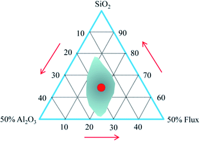
The chemical composition of the raw materials is given in Table 1. Both granite waste and coal gangue had high contents of SiO2 and Al2O3. They form the framework of the resulting ceramic and provide the mechanical strength.28 Meanwhile, there was a high content of SiO2 and Na2O in the waste glass, which provides enough amorphous phases for the sintered ceramic bodies. Besides, there was a small amount of alkaline oxide (K2O and Na2O) and alkaline earth oxide (CaO and MgO) in the granite waste and the coal gangue, which can reduce the melting temperature and the liquid-phase viscosity at elevated temperatures29 and thereby improve the sintering of the samples. The formation of a viscous matrix in a green body to retain the gas released from the foaming agent during sintering is necessary to obtain expanded bodies.30 In Table 1, the percentage of SiO2, Al2O3, and other fluxing components (CaO + MgO + Na2O + K2O + Fe2O3) in the mixture was recalculated. The ratio between SiO2 and all fluxing components is higher than 2, which is favorable to the inflation of green bodies,31 as marked in the expanding area of the Riley diagram (Fig. 1).| Constituents | SiO2 | Al2O3 | Na2O | K2O | CaO | MgO | Fe2O3 | TiO2 | LOI |
|---|---|---|---|---|---|---|---|---|---|
| a LOI (loss of ignition). | |||||||||
| Granite waste | 67.12 | 17.36 | 5.48 | 4.16 | 1.86 | 1.69 | 1.67 | 0.26 | 0.40 |
| Coal gangue | 41.86 | 21.38 | 0.48 | 2.15 | 3.19 | 0.81 | 7.03 | 0.92 | 22.18 |
| Plate cullet | 68.14 | 0.81 | 18.94 | 0.26 | 6.92 | 4.35 | 0.23 | — | 0.35 |
| Mixture | 62.17 | 16.51 | 16.52 | 0.37 | — | ||||
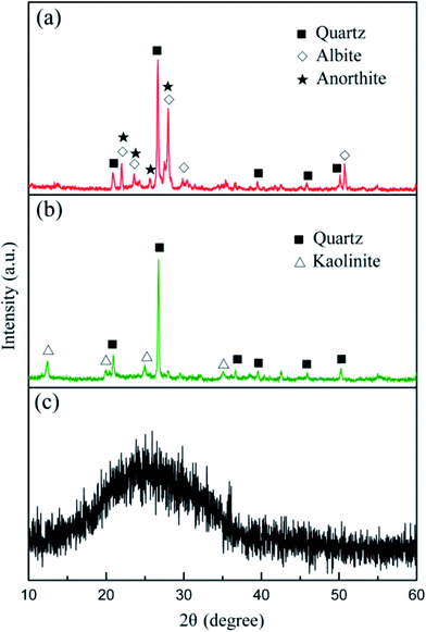
According to the XRD patterns from Fig. 2, the main mineral phases of the granite waste were quartz (SiO2, PDF no. 46-1045), albite (Na(Si3Al)O8, PDF no. 72-1246), and anorthite (CaAl2Si2O8, PDF no. 12-0301). The crystalline phases of coal gangue were quartz (SiO2, PDF no. 46-1045) and kaolinite (Al2Si2O5(OH)4, PDF no. 29-1488). An amorphous glassy phase was detected in the waste plate glass, which serves as the necessary sintering flux.
3.2 Effect of the sintering temperature on the CFs
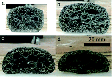
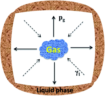
Fig. 3 presents the internal pore structure of the CFs formed at sintering temperatures between 1110 °C and 1170 °C. The samples show a different volume expansion and different pore diameters when the sintering temperature varies. The volume expansion of the samples first increases, then decreases with the increasing temperature, whereas the pore diameter increases gradually with the temperature. From 1110 °C to 1130 °C, a dramatic change in the volume expansion occurs for samples with relatively small pores (0.5–2 mm), as seen in Fig. 3a and b. When the temperature increases, the volume expansion decreases and large pores (3–8 mm) appear (Fig. 3c and d). According to the liquid sintering theory, the green body softens above the softening point and a certain amount of liquid phase appears under the action of the alkali/alkaline earth metal oxides.32,33 At lower temperatures, only a small amount of liquid phase with a high viscosity is available and a small volume of gas is released, which can lead to a volume expansion and small pores in the body. When the temperature increases, a larger amount of liquid phase with a low viscosity is generated and the gas produced makes the volume increase under the action of the surface tension, leading to the formation of large pores in the body. However, when the surface tension between the gas and the liquid phase reaches a certain level at the temperature of 1170 °C, the gas escapes and connected pores will from in the body. The expansion behavior of the samples is illustrated in Fig. 4. During the process, the most critical parameter is the matching degree between the liquid phase and the gas emission. Indeed, there is a variant balance between the gas pressure (Pg) and the surface tension of the liquid phase (γl). In fact, γl is just larger than Pg at the appropriate temperature that yields the ideal pore structure. Therefore, the evolution of the pore morphology indicates that there is a close correlation between the sintering temperature and the pore structure in the CFs based on the matching degree between the liquid phase and the gas emission.3.3 Effect of the foaming agent content on the CFs
A sintering temperature of 1150 °C was chosen to analyze the impact of the foaming agent content on the CFs. Fig. 5 shows the morphology of the samples sintered at 1150 °C for a different foaming agent content. Their corresponding pore size distribution are shown in Fig. 6. The blank sample without any foaming agent is a rather dense ceramic body (Fig. 5a) whereas the samples added with SiC present different volume expansions and different pore diameters. SiC is a typical foaming agent.14,34,35 The CO2 and CO emissions from SiC are associated with the oxidation reactions of eqn (3) and (4):| SiC (s) + 2O2 (g) → SiO2 (s) + CO2 (g) | (3) |
| 2SiC (s) + 3O2 (g) → 2SiO2 (s) + 2CO (g) | (4) |
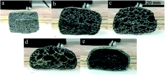 | ||
| Fig. 5 Morphology of the CFs obtained with (a) 0, (b) 0.3 wt%, (c) 0.5 wt%, (d) 1.0 wt%, and (e) 2.0 wt% foaming agent. | ||
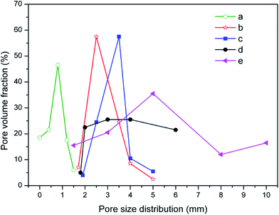 | ||
| Fig. 6 The pore size distribution of the CFs obtained with (a) 0, (b) 0.3 wt%, (c) 0.5 wt%, (d) 1.0 wt%, and (e) 2.0 wt% foaming agent. | ||
Hasheminia et al.,32 Yin et al.,13 Jiang et al.,22 Wang et al.,36 Xi et al.,35 Méar et al.,37 and Ji et al.34 produced different foamed glasses, ceramics and building insulation materials using SiC as a foaming agent. Besides, Bernardo et al.38 reported using glass foams from recycled soda-lime glass and SiC-based waste as the foaming agent. SiC is an excellent foaming agent introducing a high flexibility in various waste mixtures. In this study, the addition of SiC results in the swelling and the formation of an internal structure where both pores and pore walls are present. Increasing the content in foaming agent within a certain range contributes to improving the porosity and the volume expansion. When the foaming agent content varies from 0.3 wt% to 0.5 wt%, both the volume expansion and the pore size of the samples increase (Fig. 5b and c). The narrow curves of pore size distribution shift to the large pores, the average pore size (D50) rising from 2.53 to 3.42 mm. The sample with 0.5 wt% SiC presents a relatively plump and uniform pore structure. At this stage, the viscosity and the surface tension of the liquid phase can match up with the gas pressure and a satisfactory pore structure is obtained. Such a pore structure is very useful to improve the mechanical properties of the samples.39,40 When the foaming agent content keeps increasing, the diameter of the pores increases drastically and pores are connecting (Fig. 5d and e), thus the pore size distribution widens, shown in Fig. 6d and e. This is because an excess of foaming agent leads to excessive gas release and the gas breaks out of the surrounding liquid phase from the surface tension, which results in the formation of connected pores.
The porous structure strongly determines the resulting physical and mechanical strength of the CFs. Therefore, the effect of the foaming agent content on the bulk density, the porosity, the water absorption, and the compressive strength of the samples was determined (Fig. 7). Both the bulk density and the compressive strength first increase then decrease, whereas the porosity and the water absorption have an opposite evolution with the increasing content of foaming agent. The variation observed agrees with the morphology of the CFs. The blank sample without any foaming agent has the highest density (1219 kg m−3) and the highest compressive strength (12.58 MPa), which is equivalent to the values for typical compact ceramic products. Adding the foaming agent results in the emission of gas during the sintering process. The density and the compressive strength decrease dramatically even when only 0.3 wt% of SiC is added. The porosity and the water absorption increase sharply compared to blank sample. When the foaming agent content increases, more gas is released, which contributes to a higher porosity and higher water absorption as well as a lower density and a lower strength. However, when the foaming agent content reaches 1.0–2.0 wt%, the liquid phase is unable to sustain the high pressure generated. Therefore, the gas escapes from the liquid matrix and the pores coalesce. Consequently, an ideal structure with uniform pore diameters can only be realized through the addition of SiC at 0.5 wt%.
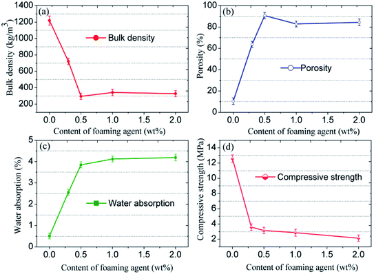 | ||
| Fig. 7 (a) Bulk density, (b) porosity, (c) water absorption, and (d) compressive strength of the CFs obtained with different foaming agent content. | ||
3.4 Effect of additives on the CFs
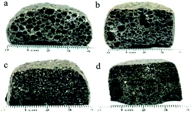
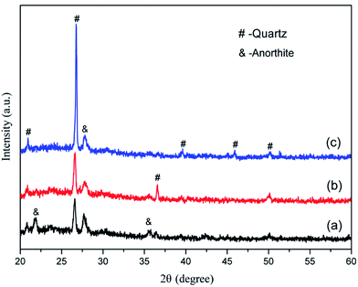
The morphology of the CFs containing 0.5 wt% foaming agent sintered at 1150 °C in the presence of CaO, MgO, Na2HPO4, and Na3PO4 is shown in Fig. 8. The CFs with different additives have different degrees of volume expansion as well as different pore sizes and porosity. This implies that the additives have a notable influence on the pore structure of the samples. Compared to the blank sample without any additive (Fig. 5c), the volume expansion of the samples with CaO and Na2HPO4 does not change significantly. However, the addition of CaO increases the pore size to 2–4 μm with a porosity of 91.9% whereas Na2HPO4 reduces the pore size to 1–2 μm and a porosity of 88.5% while keeping high pore uniformity. In contrast, MgO and Na3PO4 deteriorate the pore structure by significantly changing the pore size and reducing the uniformity. CaO and MgO are alkaline earth metallic oxides that can reduce the polymerization degree of the silicate networks by breaking Si–O bonds, resulting in lower softening temperatures, a lower liquid phase viscosity, and a lower pore expansion resistance.41,42 Later on, it also accelerates oxygen migration in liquid silicate and facilitates SiC oxidation to generate more CO2 and CO gases.35,41,43 We confirmed the role of CaO, but the addition of MgO led to an unexpected irregular coalesced pores. In previous studies, Na2HPO4 (ref. 44) and Na3PO4 (ref. 10 and 45) were used as foaming stabilizer. Ideally, they benefit the formation of a melting liquid and a glass phase. In this study, the addition of Na2HPO4 improved the distribution of the pores and reduced their pore size, whereas Na3PO4 inhibited pore formation, resulting in a less favorable pore structure. From the XRD patterns in Fig. 9, the samples without and with CaO and Na2HPO4 additives consisted of quartz and anorthite phases. They changed the intensity of the diffraction peaks but did not cause any new crystalline phases in the sintered bodies.The variations in the pore structure directly affect the physical and mechanical performance of the glass CFs. As shown in Fig. 10, the samples added with CaO had the lowest bulk density (279 ± 25 kg cm−3). The bulk density sequentially increases in the samples added with Na2HPO4, MgO, and Na3PO4, due to the continuously decreasing porosity. Correspondingly, the compressive strength increase in sequence for the samples with MgO, CaO, Na2HPO4, and Na3PO4. Consequently, the samples with CaO and Na2HPO4 have a relatively high strength of 4.81 MPa and 5.76 MPa, respectively, as well as a uniform pore structure with different scales, which meets the various practical requirements. Xi et al.46 revealed that the glass-ceramic foams with a density of 0.30 g cm−3, a compressive strength of 1.0 MPa and a thermal conductivity of 0.060 W (m−1 K−1) using extracted titanium tailing and glass waste (2![[thin space (1/6-em)]](https://www.rsc.org/images/entities/char_2009.gif) :
:![[thin space (1/6-em)]](https://www.rsc.org/images/entities/char_2009.gif) 8) with the addition of 2 wt% NaCO3 and 2 wt% B2O3, could be widely used in construction and building industry. In this study, the prepared CFs have desirable density and compressive strength, whereas the thermal properties of foams remains to be studied. Even so, the addition of the proper additive provides means to adjust the pore structure according to the actual application requirements in different areas, such as for insulation, gardening, and in lightweight construction.
8) with the addition of 2 wt% NaCO3 and 2 wt% B2O3, could be widely used in construction and building industry. In this study, the prepared CFs have desirable density and compressive strength, whereas the thermal properties of foams remains to be studied. Even so, the addition of the proper additive provides means to adjust the pore structure according to the actual application requirements in different areas, such as for insulation, gardening, and in lightweight construction.
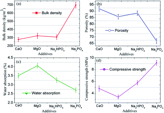 | ||
| Fig. 10 (a) Bulk density, (b) porosity, (c) water absorption, and (d) compressive strength of CFs prepared with different additives. | ||
3.5 Corrosion resistance
In practice, the sintered foams obtained are usually exposed to different external environments, including acidic and base conditions as well as other harsh surroundings. Therefore, the corrosion resistance of CFs is a crucial factor in an actual application. From the acid resistance tests, the mass loss in CFs without and with added CaO and Na2HPO4 are 1.98 ± 0.13%, 2.84 ± 0.15% and 0.97 ± 0.10%, respectively. The corresponding base resistance results are 2.43 ± 0.12%, 2.85 ± 0.15% and 2.28 ± 0.12%, respectively. The variation in the mass loss is mainly determined by the difference in the pore size and their uniformity. Increasing the pore size increases the contact area between the solid phase and the acid solution, which decreases the acid resistance correspondingly. Moreover, the addition of CaO and Na2HPO4 increases the glass phase and wraps the crystalline grains in the solid matrix, thereby preventing the reaction between the matrix and the acid solution. While the samples present much poor base resistance compared to acid resistance, which is due to the dissolution of silicon oxides of glass phase in alkali solution. Liu et al.29 revealed that the acid and alkali corrosion resistance up to 97% of glass ceramic foam materials by utilizing 20 wt% lead–zinc tailings, 48 wt% fly ash and 12 wt% red mud as well as 20 wt% sodium borate as sintering aids can meet the requirement for the industrial application. Therefore, the waste-derived foams prepared with a high acid and base stability (>97%), will give them a good prospect for many applications.4. Conclusion
Ceramic foams (CFs) were manufactured by reusing granite waste, coal gangue, and cullet while adding SiC as the foaming agent. The experimental results indicate a close correlation between the sintering temperature and the pore structure of the CFs based on the matching degree between the liquid phase and the gas emission. The addition of SiC at 0.5 wt% results in a substantial volume expansion of the green body and in the formation of an internal structure with uniform pores and thin pore-walls at a given sintering temperature. The addition of CaO and Na2HPO4 respectively enables the pores to grow and shrink along with a high pore uniformity, which meets different application requirements for insulation, gardening, and in lightweight construction. Conversely, adding MgO and Na3PO4 deteriorates the pore structure by respectively reducing the pore uniformity and inhibiting pore formation. Our results provide a good alternative to recycle mineral waste and fabricate valuable porous ceramic products at a low cost.Conflicts of interest
There are no conflicts to declare.Acknowledgements
This work was supported by the Shandong Provincial Natural Science Foundation of China (ZR2018LE004), the Major Basic Research Program of the Shandong Provincial Natural Science Foundation of China (ZR2018ZC0741), and the National Key Research and Development Program of China (2017YFC0703100) as well as the Taishan Scholars Program.References
- R. V. Silva, J. de Brito, C. Q. Lye and R. K. Dhir, J. Cleaner Prod., 2017, 167, 346–364 CrossRef CAS.
- H. X. Peng, Z. Fan and J. R. G. Evans, et al., J. Eur. Ceram. Soc., 2000, 20, 807–813 CrossRef CAS.
- M. Ciftci and B. Cicek, Res. Rev.: J. Mater. Sci., 2017, 05, 1–17 Search PubMed.
- P. O. Iniaghe and G. U. Adie, Waste Manage. Res., 2015, 33, 947–961 CrossRef CAS.
- R. Taurino, I. Lancellotti and L. Barbieri, et al., Int. J. Appl. Glass Sci., 2014, 5, 136–145 CrossRef CAS.
- J. König, R. R. Petersen and Y. Yue, Ceram. Int., 2015, 41, 9793–9800 CrossRef.
- B. Chen, Z. Luo and A. Lu, Mater. Lett., 2011, 65, 3555–3558 CrossRef CAS.
- Y. Guo, Y. Zhang, H. Huang, K. Meng, K. Hu, P. Hu, X. Wang, Z. Zhang and X. Meng, Ceram. Int., 2014, 40, 6677–6683 CrossRef CAS.
- Y. Guo, Y. Zhang, H. Huang, X. Meng, Y. Liu, S. Tu and B. Li, Constr. Build. Mater., 2016, 125, 1093–1100 CrossRef CAS.
- L. Ding, W. Ning, Q. Wang, D. Shi and L. Luo, Mater. Lett., 2015, 141, 327–329 CrossRef CAS.
- T. Liu, X. Li, L. Guan, P. Liu, T. Wu, Z. Li and A. Lu, Ceram. Int., 2016, 42, 1733–1739 CrossRef CAS.
- S. Volland, Constr. Build. Mater., 2016, 125, 119–126 CrossRef CAS.
- H. Yin, M. Ma, J. Bai, Y. Li, S. Zhang and F. Wang, Mater. Lett., 2016, 185, 511–513 CrossRef CAS.
- Q. Zhang, F. He, H. Shu, Y. Qiao, S. Mei, M. Jin and J. Xie, Constr. Build. Mater., 2016, 111, 105–110 CrossRef CAS.
- B. M. B. Jordan, J. Civ. Eng., 2017, 11, 234–238 Search PubMed.
- T. Ramos, A. M. Matos, B. Schmidt, J. Rio and J. Sousa-Coutinho, Constr. Build. Mater., 2013, 47, 1001–1009 CrossRef.
- I. Mármol, P. Ballester, S. Cerro, G. Monrós, J. Morales and L. Sánchez, Cem. Concr. Compos., 2010, 32, 617–622 CrossRef.
- P. Torres, H. R. Fernandes, S. Agathopoulos, D. U. Tulyaganov and J. M. F. Ferreira, J. Eur. Ceram. Soc., 2004, 24, 3177–3185 CrossRef CAS.
- P. Torres, H. R. Fernandes, S. Olhero and J. M. F. Ferreira, J. Eur. Ceram. Soc., 2009, 29, 23–30 CrossRef CAS.
- R. R. Menezes, H. S. Ferreira and G. A. Neves, Ceramica, 2002, 48, 92–101 CrossRef CAS.
- M. Hojamberdiev, A. Eminov and Y. Xu, Ceram. Int., 2011, 37, 871–876 CrossRef CAS.
- C. Jiang, S. Huang, G. Li, X. Zhang and X. Cheng, Ceram. Int., 2018, 44, 3469–3471 CrossRef CAS.
- M. Yang, Z. Guo, Y. Deng, X. Xing, K. Qiu, J. Long and J. Li, Int. J. Miner. Process., 2012, 102–103, 112–115 CrossRef CAS.
- Q. Lu, X. Dong, Z. Zhu and Y. Dong, J. Hazard. Mater., 2014, 273, 136–145 CrossRef CAS.
- Z. Li, Z. Luo, X. Li, T. Liu, L. Guan, T. Wu and A. Lu, J. Porous Mater., 2015, 23, 231–238 CrossRef.
- X. Fang, Q. Li, T. Yang, Z. Li and Y. Zhu, Constr. Build. Mater., 2017, 134, 358–363 CrossRef CAS.
- J. Cao, J. Lu, L. Jiang and Z. Wang, Ceram. Int., 2016, 42, 10079–10084 CrossRef CAS.
- L.-j. Hou, T.-y. Liu and A.-x. Lu, Trans. Nonferrous Met. Soc. China, 2017, 27, 591–598 CrossRef CAS.
- T. Liu, C. Lin, J. Liu, L. Han, H. Gui, C. Li, X. Zhou, H. Tang, Q. Yang and A. Lu, Ceram. Int., 2018, 44, 14393–14400 CrossRef CAS.
- H. Wang, Z. Chen, R. Ji, L. Liu and X. Wang, Ceram. Int., 2018, 44, 13681–13688 CrossRef CAS.
- E. Fakhfakh, W. Hajjaji, M. Medhioub, F. Rocha, A. Lopezgalindo, M. Setti, F. Kooli, F. Zargouni and F. Jamoussi, Appl. Clay Sci., 2007, 35, 228–237 CrossRef CAS.
- S. Hasheminia, A. Nemati, B. Eftekhari Yekta and P. Alizadeh, Ceram. Int., 2012, 38, 2005–2010 CrossRef CAS.
- A. M. M. Soltan, W.-A. Kahl, F. Abd El-Raoof, B. Abdel-Hamid El-Kaliouby, M. Abdel-Kader Serry and N. A. Abdel-Kader, J. Cleaner Prod., 2016, 117, 139–149 CrossRef CAS.
- R. Ji, Z. Zhang, Y. He, L. Liu and X. Wang, Constr. Build. Mater., 2015, 85, 119–126 CrossRef.
- X. Xi, A. Shui, Y. Li, Y. Wang, H. Abe and M. Naito, J. Eur. Ceram. Soc., 2012, 32, 3035–3041 CrossRef CAS.
- H. Wang, Z. Chen, L. Liu, R. Ji and X. Wang, Ceram. Int., 2018, 44, 10078–10086 CrossRef CAS.
- F. Méar, P. Yot and M. Ribes, Mater. Lett., 2006, 60, 929–934 CrossRef.
- E. Bernardo, R. Cedro, M. Florean and S. Hreglich, Ceram. Int., 2007, 33, 963–968 CrossRef CAS.
- B. González-Corrochano, J. Alonso-Azcárate and M. Rodas, Constr. Build. Mater., 2014, 53, 91–101 CrossRef.
- P. C. Lau, D. C. L. Teo and M. A. Mannan, Constr. Build. Mater., 2018, 176, 24–34 CrossRef CAS.
- M. Zhou, X. Ge, H. Wang, L. Chen and X. Chen, Ceram. Int., 2017, 43, 9451–9457 CrossRef CAS.
- X. Wang, D. Feng, B. Zhang, Z. Li, C. Li and Y. Zhu, Mater. Lett., 2016, 169, 21–23 CrossRef CAS.
- X. Xi, L. Xu, A. Shui, Y. Wang and M. Naito, Ceram. Int., 2014, 40, 12931–12938 CrossRef CAS.
- B. Chen, K. Wang, X. Chen and A. Lu, Mater. Lett., 2012, 79, 263–265 CrossRef CAS.
- H. Wang, K. Feng, Y. Zhou, Q. Sun and H. Shi, Mater. Lett., 2014, 132, 176–178 CrossRef CAS.
- C. Xi, F. Zheng, J. Xu, W. Yang, Y. Peng, Y. Li, P. Li, Q. Zhen, S. Bashir and J. L. Liu, Constr. Build. Mater., 2018, 190, 896–909 CrossRef CAS.
| This journal is © The Royal Society of Chemistry 2019 |

