 Open Access Article
High efficiency dye-sensitized solar cells with VOC–JSC trade off eradication by interfacial engineering of the photoanode|electrolyte interface†
Anantharaj Gopalraman *ab,
Subbian Karuppuchamyc and
Saranyan Vijayaraghavan*ab
aCorrosion and Materials Protection Division, CSIR-Central Electrochemical Research Institute, Karaikudi, Tamil Nadu 630003, India. E-mail: anantharaj.che@gmail.com; saranyan@cecri.res.in
bAcademy of Scientific and Innovative Research, India
cDepartment of Energy Science, Alagappa University, Karaikudi, Tamil Nadu 630003, India
First published on 4th December 2019
Abstract
Interfacial modification of the photoanode|electrolyte interface using oleic acid (OA) is thoroughly investigated in this present study. The overall photoconversion efficiency of 11.8% was achieved under the illumination of 100 mW cm−2 with an optical filter of AM 1.5 G. OA molecules were meant to be adsorbed on to the vacant areas of the TiO2 and the OA moieties leached out the aggregated C106 dye molecules from the TiO2 surface. There was a strong spectral overlap between the absorption spectrum of donor (OA) and the emission spectrum of acceptor (C106), leading to effective Förster Resonance Energy Transfer (FRET) between OA and C106 and suggested an excellent opportunity to improve the photovoltaic performances of DSSCs. UV-vis DRS and UPS analysis revealed that OA molecules created new surface (mid-gap energy) states (SS) in TiO2 and these SS played a major role in the electron transport kinetics. Mott–Schottky analysis of DSSCs under dark conditions was carried out to find the shift in the flat band potential of TiO2 upon OA modification. Surprisingly, no trade off between VOC and JSC was observed after interfacial modification with OA. The dynamics of charge recombination and electron transport at the photoanode|electrolyte interface were studied in detail using electrochemical impedance spectroscopy.
1. Introduction
Harvesting solar energy by photovoltaic devices received stupendous attention in the past decades since it is clean, eco-friendly and abundant in nature. Among the third generation solar cells, dye-sensitized solar cells (DSSC) have attained immense attention due to their economic viability, ease of fabrication and vast potential to be used as an alternative for the conventional silicon-based solar cells.1 A typical DSSC is made up of dye impregnated nanocrystalline TiO2 on a transparent conducting oxide (TCO) glass substrate serving as a photoanode, platinum based counter electrode, and a redox electrolyte containing I3−/I− between the electrodes. The main working mechanism of a DSSC is as follows. Firstly, the dye molecules adsorbed onto a TiO2 photoanode upon excitation by sun light irradiation. Then, the photo-generated electrons are injected into the conduction band (CB) of TiO2 from the dye molecules. The oxidized dye molecules are reduced by I− present in the electrolyte. Finally, the I3− ions formed in the dye regeneration process are reduced back to I− at the counter electrode. It is noteworthy that high photoconversion efficiency (PCE) is one of the important parameters for the real time application and commercialization of DSSCs.2 Numerous attempts and research strategies have been adopted to boost the efficiency of DSSCs. Recently, using silyl anchor organic dye along with Co(III)/Co(II) red–ox couple, a PCE of 14.7% was achieved by collaborative sensitization process.3 Besides, some of the other paramount attempts to enhance the efficiency of DSSC are: (i) molecular engineering of new sensitizers with extended light absorption up to near IR regions,4 (ii) discovery of new red–ox couples with more positive reduction potential than that of conventional I3−/I− red–ox couple,5 (iii) searching for new additives to overcome the charge recombination processes and VOC–JSC trade-off,3 (iv) designing of new co-adsorbents to prevent the competitive adsorption of dye molecules and photoexcited state quenching.6A distinct feature of the DSSC compared to the other solar cell technologies is that the light harvesting, electron transport and hole transport processes are taking place in different components within the device. For example, light is absorbed by dye molecules anchored on TiO2, electrons are injected from dye to CB of TiO2, and the hole transport processes occur in the electrolyte.7 This enables researchers to develop a variety of component materials, with the careful consideration of engineering the energy-levels at interfaces. If the component materials designed to be well-matched at interfaces, the DSSC as a whole system will show superior functionality surpassing the sum of the properties of the individual component materials.8 As a matter of fact, photoanode|electrolyte interface in DSSCs play a crucial role in determining the cell performance. For example, both processes of charge separation and dye regeneration takes place at the dye|TiO2|electrolyte interface. These two processes are favorable for the overall energy conversion. Concurrently, the recombination of injected electrons in the TiO2 film with the oxidized dye or with I3− also occurs at this interface, which is unfavorable to the photon-to-electricity conversion process. Thus, the overall cell performance should be greatly improved by efficiently propelling the favorable processes and suppressing the unfavorable energy loss by suitable modification on the electrode|electrolyte interface.
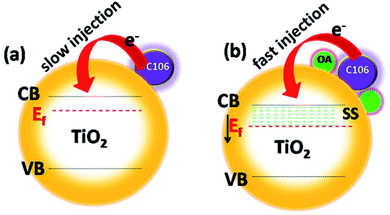
Numerous efforts have been made to modify photoanode|electrolyte interface to prevent the charge recombination process, and to boost the charge transfer kinetics and thereby improving the photovoltaic performances. Charge recombination process is strongly prevented by engineering this interface by coating the thin insulating layers of metal oxides, sensitization of TiO2 surface along with co-adsorbents, co-sensitization of dyes with co-adsorbent molecules having strong absorption in the visible region not governed by a sensitizer molecule and using additives in electrolyte.5 The use of co-adsorbents is being considered as one of the most successful efforts for the improvement of the photovoltaic performance of DSSCs. Co-adsorbents are meant to be adsorbed on TiO2 surface along with sensitizing dyes and cover the naked area of the TiO2 surface uncovered by the dye molecules.6 Co-adsorbents are organic molecules which contain long, hydrophobic alkyl chain on one end and carboxylic or phosphonic acid group on the other end. Along with dye molecules the co-adsorbents form a compact layer and block the vacant areas on TiO2 surface. The long alkyl chain act as a buffer between the electrons in the CB of TiO2 and I3−. Hence, the unwanted charge recombination process is prevented. Deoxycholic acid (DCA) is widely used co-adsorbent in DSSC for repressing dye aggregation problems in DSSCs.9 DCA is used in DSSC along with various sensitizing dyes include ruthenium pyridyl complexes, coumarin, porphyrin, phthalocyanine, etc. Both photovoltage and photocurrent were greatly improved when DCA and its derivatives were used as a co-adsorbent.10–12 Organic compounds with carboxylic functionalities as anchoring groups such as 4-guanidinobutyric acid,13 hexadecylmalonic acid,14 ω-guanidinoalkyl acids,15 citric acid16 and stearic acid17 are successfully used as co-adsorbents and showed appreciable photovoltaic performances. Co-adsorbents with phosphonate groups have showed a strong affinity towards the binding on TiO2. While using dineohexylphosphinic acid (DINHOP), the triiodide reduction was greatly suppressed and resulted in enhanced VOC.18 It was demonstrated that the charge recombination process was prevented by reducing the surface concentration of dye–iodine complex.19 Recently, post treatment of TiO2 photoanode with co-adsorbents after the dye adsorption has allowed improvement in the photovoltaic performances of DSSCs by preventing the recombination process.20 Though all those efforts have resulted in superior photovoltaic performances, most of the attempts were resulted in a notable VOC–JSC trade off in the photovoltaic performances. Interfacial engineering of the photoanode|electrolyte interface could be the solution to improvise the efficiency irrespective of VOC–JSC trade-off restrictions that limit the overall device performances. Following these protocols, here we have utilized oleic acid (OA, omega-9-fatty acid) as an interfacial modifier over TiO2-C106 photoanode. Here, the use of C106 as a sensitizer is ascribed to its high molecular stability and its superior photovoltaic performances among the other RuII complexes according to the earlier reports.21 The intentional addition of OA over the TiO2–C106 photoanode resulted the whole TiO2 surface is fully occupied by both C106 and OA molecules. OA molecules created new surface states (SS) in TiO2 and the Fermi level (Ef) of TiO2 shifted to positive direction that facilitated the charge injection from C106 dye to TiO2 (Scheme 1). Surprisingly, no VOC–JSC trade off was observed and the overall PCE of 11.8% was achieved with the interfacial engineering of photoanode using OA. Electrochemical impedance spectroscopy analyses were carried to get a deeper understanding of the role of OA on the charge transport kinetics and the deeper understanding of the mechanism is discussed in detail.
2. Experimental
2.1. Chemicals and reagents
All chemicals used in this study were of analytical grade. TiO2 (P25), chloroplatinic acid hexahydrate and oleic acid (99%), 1,3-dimethyl-3-propyl imidazolium iodide (DMPII, 99%), lithium iodide (LiI, 99.9%) iodine (I2, 99.9%), tertiary butyl pyridine (TBP, 96%), guanidine thiocyanate (GSCN, 99%), diethanolamine, titanium(IV) butoxide, fluorine doped tin oxide coated glass (FTO glass, 2.2 mm thickness, sheet resistance 7 Ω □−1) were purchased from Sigma Aldrich India Private Ltd., India. C106 dye (cis-bis(isothiocyanato)(2,2′-bypyridyl-4,4′-dicarboxylato)(4,4′-bis(5-(hexylthio)thiophen-2-yl)-2,2′-bypyridyl)ruthenium(II)) was purchased from Dyesol. Other reagents were purchased from TCI India Pvt. Ltd., India and used as received without further purification.2.2. Device fabrication
The detailed procedure for the fabrication of DSSCs is as follows. FTO glasses were cut into 2.0 × 1.5 cm2 sized pieces and were cleaned in detergent solution, distilled water, acetone and ethanol in an ultrasonic bath and the glasses were also subjected to UV/O3 treatment. The blocking layer of TiO2 was deposited by spin coating of an acidic solution of titanium(IV) isopropoxide and sintered at 450 °C for 30 min. Anatase TiO2 was synthesized as follows: to 34.5 mL of distilled water, 2 mL of diethanolamine was added under constant stirring. About 3.4 mL of titanium(IV) butoxide was added dropwise to the diethanolamine solution. The whole contents were allowed to stir for about 30 minutes at room temperature. Then, the reaction mixture was heated in Teflon lined autoclave at 180 °C for 16 hours. After cool down to room temperature, the TiO2 nanoparticles were isolated by centrifugation at 5000 rpm, washed several times with absolute ethanol and dried at 80 °C for an hour. Thus obtained TiO2 powder was sintered at 450 °C for 30 minutes. The average crystallite size of the TiO2 nano particles were calculated as 15 nm by Debye–Scherrer formula. The corresponding XRD pattern is presented as Fig. S1.† TiO2 film was coated on pre-cleaned FTO glasses by doctor blade method. The TiO2 paste prepared by grinding anatase TiO2 nanoparticles (0.5 g) with 0.15 g of polyethylene glycol (MW-35![[thin space (1/6-em)]](https://www.rsc.org/images/entities/char_2009.gif) 000), 0.1 g of poly ethylene oxide (MW-100
000), 0.1 g of poly ethylene oxide (MW-100![[thin space (1/6-em)]](https://www.rsc.org/images/entities/char_2009.gif) 000), Triton-X-100 (two drops) and 3.5 mL of 0.1 M glacial acetic acid for an hour. The whole contents were allowed to be stirred for 24 hours. The obtained paste was coated on a cleaned FTO glasses by doctor-blade method to obtain smooth and flat surface using adhesive tape. Finally, the TiO2 coated FTO glasses were gradually heated to remove the organic contents in a muffle furnace under constant air flow at 150 °C for 15 min, 350 °C for 10 min, 450 °C for 15 min, 500 °C for 30 min. The TiO2 coated glasses were cooled to 70 °C and immersed in 0.3 mM solution of C106 dye in tert-butyl alcohol–acetonitrile mixture (1
000), Triton-X-100 (two drops) and 3.5 mL of 0.1 M glacial acetic acid for an hour. The whole contents were allowed to be stirred for 24 hours. The obtained paste was coated on a cleaned FTO glasses by doctor-blade method to obtain smooth and flat surface using adhesive tape. Finally, the TiO2 coated FTO glasses were gradually heated to remove the organic contents in a muffle furnace under constant air flow at 150 °C for 15 min, 350 °C for 10 min, 450 °C for 15 min, 500 °C for 30 min. The TiO2 coated glasses were cooled to 70 °C and immersed in 0.3 mM solution of C106 dye in tert-butyl alcohol–acetonitrile mixture (1![[thin space (1/6-em)]](https://www.rsc.org/images/entities/char_2009.gif) :
:![[thin space (1/6-em)]](https://www.rsc.org/images/entities/char_2009.gif) 1) overnight for dye anchoring on TiO2. The dye coated film was washed thoroughly with absolute ethanol to remove unabsorbed dye molecules and dried over the N2 flow. For OA modification, the TiO2/C106 dye coated films were immersed in tert-butyl alcohol–acetonitrile mixture solution of OA for three hours and washed with absolute ethanol and dried under nitrogen flow.
1) overnight for dye anchoring on TiO2. The dye coated film was washed thoroughly with absolute ethanol to remove unabsorbed dye molecules and dried over the N2 flow. For OA modification, the TiO2/C106 dye coated films were immersed in tert-butyl alcohol–acetonitrile mixture solution of OA for three hours and washed with absolute ethanol and dried under nitrogen flow.
The dye coated TiO2 or OA modified TiO2/dye film was sandwiched with a pre-drilled counter electrode (platinum coated glass, 5 mM solution of chloroplatinic acid in isopropyl alcohol was drop casted on pre-cleaned FTO glass and heated at 435 °C for 15 min). Two electrodes were separated by hot melt polymer film with the thickness of 60 μm (Meltonix-1170-60). Red–ox electrolyte consisting of 0.6 M DMPII, 0.05 M LiI, 0.03 M I2, 0.5 M TBP and 0.1 M GSCN in acetonitrile and valeronitrile mixture (1![[thin space (1/6-em)]](https://www.rsc.org/images/entities/char_2009.gif) :
:![[thin space (1/6-em)]](https://www.rsc.org/images/entities/char_2009.gif) 1), was injected into the device and sealed. The active areas of the fabricated DSSCs were of 0.16 cm2. The amount of dye loading was determined by desorbing the adsorbed dye from 12 μm thick TiO2 in 0.1 M NaOH. The area of the TiO2 film was 0.15 cm2. The concentration of the desorbed dye solution was determined by Beer–Lambert's law.
1), was injected into the device and sealed. The active areas of the fabricated DSSCs were of 0.16 cm2. The amount of dye loading was determined by desorbing the adsorbed dye from 12 μm thick TiO2 in 0.1 M NaOH. The area of the TiO2 film was 0.15 cm2. The concentration of the desorbed dye solution was determined by Beer–Lambert's law.
2.3. Instrumentation
X-ray diffraction of TiO2 was measured using Cu Kα radiation (1.5418 Å, Bruker, D8 ADVANCE). Optical absorption spectra were obtained using UV-VIS-NIR spectrophotometer (Cary 5000, Varian) for thin films of TiO2|dye with and without OA. FT-IR spectra were recorded using a spectrometer (TENSOR 27, Brucker). Room temperature PL spectra were recorded using a spectrofluorometer (FP-8500, JASCO). All electrochemical investigations were carried out by using a potentiostat–galvanostat (SP-150, Bio-logic). The photovoltaic performances of fabricated devices were tested at 100 mW cm−2 with an optical filter of AM 1.5 G using (Sciencetech-AAA solar simulator) coupled with Keithley-2400 voltage meter. Electrochemical impedance spectroscopy measurement was carried out at an AC amplitude of 10 mV and in a frequency range from 105 Hz to 10−2 Hz. Mott–Schottky analysis was carried for the DSSCs under dark conditions at 1 kHz of frequency. Ultraviolet photoelectron spectroscopy measurements (ESCALAB 250 Xi, Thermo Scientific) were carried with a negative bias voltage (−2 V) applied to the samples using the He(I) (21.2 eV). The binding energy scale values were calibrated using Au. For UPS measurement the samples TiO2 and TiO2/OA were coated on FTO glasses without any binder. Incident photon to current conversion efficiency (IPCE) spectra was measured by using Opto-Solar instrument (GmbH SR300/300).3. Results and discussion
3.1. Influence of OA on photovoltaic performances
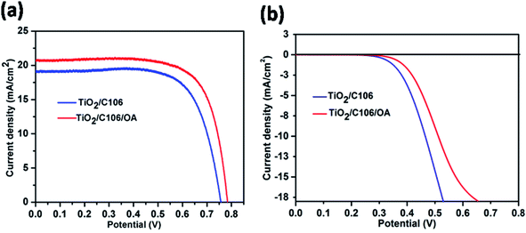
To probe the effect of OA on device performance, DSSCs were fabricated by adsorbing OA on TiO2 photoanode after C106 dye adsorption. Hence, the OA molecules were meant to be anchored on the vacant sites of TiO2 surface only. Thus, the entire surface of TiO2 is covered by both OA and C106 dye and form a compact and network structure. Photovoltaic performance of DSSCs were evaluated under the illumination of 100 mW cm−2 with an optical filter of AM 1.5 G. The current density–potential curves (J–V) are presented in Fig. 1(a).To ensure the reproducibility of the obtained data, there were five separate DSSCs fabricated and the average values were summarized in Table 1. As can be seen from the data presented in Table 1, photovoltaic performance of DSSC with C106 dye with OA (TiO2/C106/OA) was greatly improved in terms of enhancement in open circuit voltage (VOC), short circuit current density (JSC) and fill factor (FF). Interestingly, incorporation of OA substantially improves the performance of DSSC and a PCE of 11.8% was achieved without VOC–JSC trade off. From the J–V curve, VOC, JSC and FF of the device with OA were determined as 0.784 V, 20.7 mA cm−2 and 0.73 respectively. However, the device TiO2/C106 showed a PCE of 10.3% with VOC, JSC and FF of 0.757 V, 19.2 mA cm−2 and 0.73 respectively. In addition, DSSC sensitized with OA alone was carried out. A PCE of 0.1% achieved with VOC, JSC and FF of 0.48 V, 0.89 mA cm−2 and 0.42, respectively (Fig. S2†). This result suggested that OA also contributed significantly in the observed PCE of 11.8% for the device TiO2/C106/OA. The incident-photon-current-conversion efficiency (IPCE) curves are presented in Fig. S3(a).† Broad conversion was observed ranging from 400 nm to 700 nm due to the panchromatic absorption of the MLCT band of the C106 dye. The device fabricated without OA, an IPCE maxima of 77% was observed at 540 nm but in the case of TiO2/C106/OA device, the IPCE maxima of 80% was observed at 540 nm. This was in good agreement with the observed JSC enhancement measured under the illumination of 100 mW cm−2 for the device TiO2/C106/OA. By carefully looking the tails of the IPCE curves at lower wavelength region, the absorption of OA molecule on the photoanode along with C106 dye enables the conversion of lower wave length region photons by ca. few nm without affecting the longer wavelength photons significantly. The integrated JSC spectra are presented as Fig. S3(b).† Integrated JSC of 20 mA cm−2 and 18.5 mA cm−2 were observed for the devices TiO2/C106/OA and TiO2/C106, respectively. The observed JSC value under illumination condition is in good agreement, within 4% mismatch, with the integrated JSC values.
| Device | VOC (V) | JSC (mA cm−2) | FF | Efficiency (%) |
|---|---|---|---|---|
| TiO2/C106 | 0.757 | 19.2 | 0.71 | 10.3 |
| TiO2/C106/OA | 0.784 | 20.7 | 0.73 | 11.8 |
The charge recombination of photo-injected electron in the CB of TiO2 with I3− ions present in the electrolyte was one of the detrimental processes that limit the real time application of DSSCs. The vacant sites on the TiO2 surface act as active sites for the above mentioned recombination reaction.22 Under dark conditions, the electrons were injected from TCO to TiO2. Dye molecule has no rule as a sensitizer rather it acts as a blocking layer to prevent the recombination of electron with I3−. Fig. 1(b) shows the J–V response of DSSCs under the dark condition. It is clearly seen from the Fig. 1(b) that the device TiO2/C106/OA had a smaller current density compared to the TiO2/C106 device. As the OA molecules were attached to the naked areas of TiO2, the access of triiodide species for the recombination is prevented. It is clearly revealed that OA molecules anchored on TiO2 surface along with C106 dye inhibit the direct contact of I3− with the TiO2 surface. This was reflected in the observed VOC enhancement as well as in PCE of OA modified device (Table 1).
3.2. UV-vis and FT-IR analysis
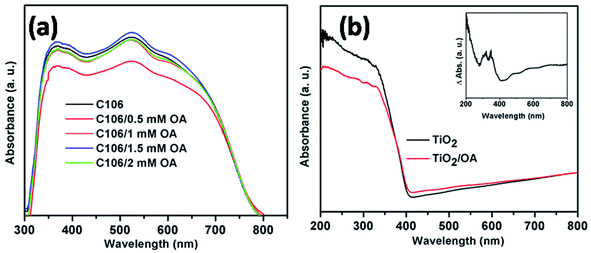
In DSSCs the extended light absorption by a sensitizer covering the wavelength ranging from visible to near IR region is crucial for the superior photovoltaic performances. UV-vis analysis was carried out to study the optical absorption and light harvesting ability of the C106 dye. Fig. S4† shows the UV-vis spectrum of C106 dye in DMF solution. Three intense bands were observed at 316, 348 and 398 nm and the low energy MLCT transition band was observed at 548 nm. The molar extinction co-efficient (ε) of C106 at 548 nm was found to be 1.7 × 10³ M−1 cm−1. The presence of excessive dye molecules in the form of molecular aggregates on the TiO2 surface lead to the photoexcited state quenching and this will affect the overall device performance.23The optical absorption spectra of TiO2/C106 photoanodes adsorbed with various concentration of OA is presented in Fig. 2(a). As can be seen from the Fig. 2(a), the OA had a strong influence on the C106 dye optical adsorption spectrum. The absorption maxima was lowered when TiO2/C106 photoanode was immersed in OA solution of 0.5 mM and the absorption started to demonstrate a marginal increase while increasing the concentration further. At a concentration of 1.5 mM of OA, the absorption of TiO2/C106 dye showed a marked difference and slightly red shifted. The main reason for this observation could be that the OA molecules leached out the aggregated dye molecules from the TiO2 surface.
This can be proved by estimating the amount of dye adsorbed on TiO2 surface before and after OA (1.5 mM) adsorption. The amount of C106 dye molecules present in the TiO2/C106 and TiO2/C106/OA photoanodes were calculated as 5.2 × 10⁻⁵ mol cm−2 and 4.9 × 10⁻⁵ mol cm−2 respectively. This clearly indicates that the excess dye molecules were being leached out via OA treatment. To further understand the influence of OA on the optical properties of C106, diffuse reflectance UV-vis spectra (DR UV-vis) of TiO2 and TiO2/OA films were recorded. As shown in Fig. 2(b), the absorption of TiO2/OA film shows a marked difference in the absorption features. To understand this further, DR UV-vis of TiO2/OA film was measured by taking TiO2 as a reference and was presented as an inset of Fig. 2(b). The inset in Fig. 2(b) clearly shows that the observed absorption was due to the creation of new surface states by OA molecules anchored on TiO2. Essentially, these surface states forms mid gap energy states that play a major role in the electron transport kinetics. FT-IR spectra were recorded for C106, OA, TiO2/C106, TiO2/OA, TiO2/C106/OA and presented as Fig. S5.† Both C106 dye and OA show a characteristic peak at 1711 cm−1 corresponding to the free –COOH group present in the C106 dye and OA but this peak was disappeared in the TiO2/C106 and TiO2/OA which indicates that –COOH was chemically bonded on TiO2. TiO2/C106 sample shows the asymmetric (νas) and symmetric (νs) stretching vibrations around 1628 and 1442 cm−1, respectively. The differences between these two stretching vibrations (Δ = νas − νs) give the information about the binding mode of –COOH group on TiO2.20 The Δ value was found to be 186 cm−1, suggesting that the –COOH was bonded on TiO2 through bridging bidendate mode. Similarly, in the case of TiO2/OA, the Δ value was found to be 182 cm−1. Hence, the both C106 and OA molecules were adsorbed on TiO2 through bridging bidendate mode and thus forming a compact structure on TiO2 surface.
3.3. Förster resonance energy transfer (FRET) between OA and C106
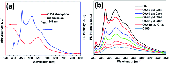
It is known that OA can act both as an emitter and sensitizer. Therefore, the understanding of the emission properties of OA and its interaction with C106 dye provides more information about the photocurrent enhancement and improved PCE. Förster resonance energy transfer (FRET) is a photophysical process in which one molecule (donor) may transfer its absorbed energy to another molecule (acceptor) separated by a distance of few nanometers in a non-radiative manner.24 This phenomenon is quite interesting since there is no need of physical contact or charge exchange between the donor and acceptor molecules. The main criterion for FRET is the emission spectrum of the donor (absorbing at lower wavelength) must be overlapped with the absorption spectrum of the acceptor (absorbing at longer wave length).25 Here, the absorption spectrum of C106 dye solution is strongly overlapping with the emission spectrum of OA solution excited at 365 nm (Fig. 3(a)) leads to an in situ FRET. This indicates that the donor OA molecule effectively transfer the energy to the acceptor C106 dye molecules.This can be further elaborated as the emission of FRET donor is steadily quenched by the addition of FRET acceptor with various concentrations ranging from 2 μM to 10 μM (Fig. 3(b)). This in situ FRET phenomenon has the strong influence in the JSC enhancement in DSSCs.26 Consequently, the overall performance of DSSC with TiO2/C106/OA photoanode is improved. Hence, FRET is providing an excellent opportunity to improve the DSSC performance by overcoming many obstacles.
3.4. Electrochemical impedance spectroscopy analysis under light condition
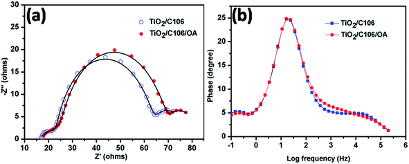
Charge transport kinetics of DSSCs was elucidated using electrochemical impedance spectroscopy. At proper conditions and equivalent circuit model, the electron transport parameters such as charge recombination resistance at photoanode|electrolyte interface, electron transport in mesoporous TiO2 network and electron life time can be obtained from impedance spectra.27 EIS spectra of DSSCs with and without OA modifications under the illumination of 100 mW cm−2 were presented in Fig. 4(a). The experimental data were fitted using an equivalent circuit model as shown in Scheme S1† and the electron transport parameters were calculated from the reported literatures.28,29 The calculated electron transport parameters are presented in Table 2.| Device | RS (Ω) | Rct (Ω) | Cp (mF) | τ (ms) | keff (s−1) | Rt (Ω) | ns (cm−3) | Rct/Rt |
|---|---|---|---|---|---|---|---|---|
| TiO2/C106 | 16.42 | 38.28 | 1.59 | 60.86 | 16.33 | 0.75 | 4.12 × 10¹⁸ | 51.04 |
| TiO2/C106/OA | 17.06 | 40.66 | 1.51 | 61.39 | 16.21 | 0.53 | 1.27 × 10¹⁸ | 76.71 |
The total series resistance RS of TiO2/C106/OA device was slightly increased from 16.42 to 17.06 Ω. However, OA modified device exhibited a higher charge recombination resistance Rct (40.66 Ω) compared to the unmodified device (38.28 Ω), indicating that the back electron transport was prevented upon OA modification. Electron life time calculation also showed a similar trend suggesting that OA molecules anchored in TiO2/C106 photoanode prevent the recombination of CB electron of TiO2 with I3−. Furthermore, the mid frequency peak of Bode plot (Fig. 4(b)) was shifted to a lower frequency side for the case of OA modified device, suggesting a longer electron life time. The network structure formed by the OA along with C106 dye at the photoanode|electrolyte interface prevents the interaction of I3− with the CB electron of TiO2. As a result, VOC of the OA modified device was improved without any loss in JSC. Charge accumulation at the photoanode|electrolyte interface can be visualized by the estimation of chemical capacitance (Cp). TiO2/C106/OA device shows lower Cp of 1.51 mF than that of the device TiO2/C106. This result is reflected in the calculated steady state electron density ns values as well (Table 2).30 The electron transport resistance in the TiO2 network was reduced for the OA modified device (0.53 Ω) while the Rt of 0.75 Ω was observed for unmodified device. In addition, a higher value of Rct/Rt was recommended for an enhanced photovoltaic performance of DSSC in terms of low charge recombination and high charge collection efficiency.31
A higher value Rct/Rt of 79.71 was found for the OA modified device which strongly supports the observed enhanced PCE. VOC decay analysis was carried out and it was found that TiO2/C106/OA device demonstrated slower decay profile suggesting a longer electron life time (Fig. S6†). The results obtained from the EIS analysis under the illumination of 100 mW cm−2 strongly supported enhancement of PCE by 11.8% via the modification of TiO2/C106 photoanode|electrolyte interface using OA.
3.5. Influence of OA on the electron transport parameters of DSSCs
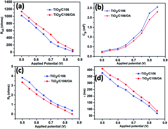
Further to elaborate the effect of OA on photovoltaic performances, EIS analyses were carried out under dark conditions with various applied bias potentials. The extracted electron transport parameters were presented as a function of applied potentials range from 0.5 to 0.85 V in Fig. 5.Under dark conditions, TiO2 considered as an electrical insulator but it becomes conductive by applying bias potentials.32,33 The charge recombination predominantly takes place at the TiO2 surface only. Fig. 5(a) shows the variation of Rct in respect to the applied potentials. Device TiO2/C106/OA showed an increased Rct values in the entire applied potential window when compared to the device TiO2/C106. Since the TiO2 surface was fully covered with C106 and OA molecules, the electron transport to the electrolyte was prevented. On the other hand the calculated Cp values were lower with respect to the applied bias potentials as shown in Fig. 5(b). This result reflected in the variation of ns as a function of applied potentials. The device TiO2/C106/OA showed lower ns values in the entire range of potentials (Fig. S7†). This infers that the charge accumulation at the interface has been reduced due to the presence of OA molecules and hence the CB edge of TiO2 was shifted to upward direction. Furthermore, the TiO2/C106/OA device showed lower Rt in the entire range of applied potentials inferring that the photoinjected electrons are effectively percolated through the TiO2 network and effectively collected by the external load without any impediment. As can be seen from the Fig. 5(d), TiO2/C106/OA device have shown higher electron life than that of the TiO2/C106 device. These results clearly revealed that the OA molecules not only prevent the back electron transfer but also greatly improve electron transport kinetics in DSSC.
3.6. Mott–Schottky and UPS analysis
In DSSC, VOC is one of the important parameters that determine the PCE, which can be derived from the difference between quasi-Fermi levels (Ef) of TiO2 and the standard reduction of potential of red–ox couple. VOC of the DSSC can be tuned either by using the red–ox couples with more positive potentials or shifting the Ef of TiO2 to negative potentials.2As can be seen from Table 1, the TiO2/C106/OA device showed higher VOC of 0.784 V than that of the device TiO2/C106 (0.757 V). To probe the VOC enhancement upon OA modification, Mott–Schottky analysis was carried out for the devices under dark condition at a frequency of 1 kHz (ref. 31 and 34) and is presented in Fig. 6(a). TiO2/C106 device showed the flat band potential Efb of −0.413 V and this value shifted positively to −0.404 V upon OA modification. One can expect that modified device must have lower VOC than the unmodified device since the Efb of unmodified device shows more negative value than that of the OA-modified one. But based on the results obtained from the J–V measurement at dark condition, EIS analysis carried out under both light and dark condition, strongly suggested that the observed VOC enhancement in the TiO2/C106/OA is mainly due to the reduced charge recombination. The built-in-potential in device (difference between the Efb of OA modified and unmodified devices) was found to be 9 mV, which was responsible for the charge separation and suppressed back electron transfer rate.
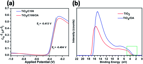 | ||
| Fig. 6 Mott–Schottky plots of DSSCs under dark condition measured at a frequency of 1 kHz (a), ultraviolet photoelectron spectra He(I) for TiO2 and TiO2/OA samples coated on FTO glass substrates (b). | ||
The shift in the Efb towards positive potential direction also manifests the charge injection from LUMO of C106 dye to CB of TiO2 (Scheme 1). In addition, it was also expected that the work function of photoanode TiO2/C106/OA supposed to be increased since the work function is the energy difference between Ef and vacuum. Furthermore, the electron withdrawing nature of –COOH group present in the OA moiety takes away the dipole formed at the interface.35
UPS characterization using He(I) radiation was carried out to probe the change in work function of TiO2 before and after OA modification and the results are illustrated in Fig. 6(b). The UPS spectra shows two distinct peaks: a broad one appeared at 6 eV corresponds to π (non-bonding) and the narrow one at 8 eV corresponds to σ (bonding) O2p orbitals of TiO2.36 The work function of TiO2 was found to be 4.1 eV by subtracting the secondary electron onset located at the higher binding energy side from He(I) photon energy 21.2 eV.37 The work function value of TiO2|OA, was found to be 4.4 eV. The creation of additional energy levels due to the surface states (SS) by anchoring OA was clearly witnessed in the spectra near the lower binding energies (also see, Scheme 1(b)) and hence, the charge injection from dye to TiO2 was greatly improved. There was a significant shift in the spectra at the higher binding energy edges. Such shift is known as vacuum level shift (Δ) and had been found at the semiconductor|metal, organic|inorganic, and organic|metal interfaces due to the formation of electric dipoles at the interface.38 Thus, the anchoring of dye/OA over TiO2 surface introduces the electric dipole at the interface that will facilitate the charge separation.
4. Conclusions
In summary, the interfacial modification of photoanode|electrolyte interface using OA has allowed to set a new bench mark PCE of 11.8% using C106 dye as a sensitizer along with the conventional I−/I3− as an electrolyte. The OA molecules leached out the excess aggregated dye molecules from the TiO2 surface and occupied the vacant sites of TiO2. The OA molecules not only prevented the charge recombination process but also helped in improving the charge transfer kinetics. The Fermi level of TiO2 was shifted to positive potential direction upon OA anchoring and facilitated the charge injection process from highest molecular orbital of C106 dye to CB of TiO2. Furthermore, the observed in situ FRET between OA and C106 dye could also play a vital role in the observed PCE. Through this interfacial modification of photoanode|electrolyte interface using OA with C106 dye, there were no VOC–JSC trade off was observed.Author contributions
The manuscript was written through contributions of all authors. All authors have given the approval for the final version of the manuscript.Conflicts of interest
There are no conflicts of interest to disclose.Acknowledgements
The author GA acknowledges the Council of Scientific and Industrial Research (CSIR), New Delhi for the Senior Research Fellowship. The authors acknowledge the Central Instrumentation Facility Division of CSIR-CECRI for characterization facilities. Authors acknowledge Science and Engineering Research Board (SERB) for the financial support. The author SK acknowledge the MHRD RUSA (Phase 2.0), Govt. of India for the financial support.References
- B. O'Regan and M. Grätzel, Nature, 1991, 353, 56–58 CrossRef
.
- S. Zhang, X. Yang, Y. Numata and L. Han, Energy Environ. Sci., 2013, 6, 1443–1464 RSC
.
- K. Kakiage, Y. Aoyama, T. Yano, K. Oya and J. I. Fujisawa, Chem. Commun., 2015, 15894–15897 RSC
.
- J. Yum, E. Baranoff, S. Wenger, M. K. Nazeeruddin and M. Grätzel, Energy Environ. Sci., 2011, 4, 842–857 RSC
.
- H. Tiana and L. Sun, J. Mater. Chem., 2011, 21, 10592–10601 RSC
.
- V. S. Manthou, E. S. Pefkianakis, P. Falaras and G. C. Vougiokalakis, ChemSusChem, 2015, 8, 588–599 CrossRef CAS PubMed
.
- Y. Numata, C. Qin, S. Zhang, L. Han and X. Yang, J. Mater. Chem. A, 2013, 2, 5167–5177 Search PubMed
.
- A. Hagfeldt, G. Boschloo, L. Sun, L. Kloo and H. Pettersson, Chem. Rev., 2010, 110, 6595–6663 CrossRef CAS PubMed
.
- A. Kay and M. Grätzel, J. Phys. Chem., 1993, 6272–6277 CrossRef CAS
.
- S. Y. Bang, M. J. Ko, K. Kim, J. H. Kim, I. H. Jang and N. G. Park, Synth. Met., 2012, 162, 1503–1507 CrossRef CAS
.
- Z. S. Wang, Y. Cui, Y. Dan-oh, C. Kasada, A. Shinpo and K. Hara, J. Phys. Chem. C, 2007, 111, 7224–7230 CrossRef CAS
.
- H. Ozawa, R. Shimizu and H. Arakawa, RSC Adv., 2012, 2, 3198–3200 RSC
.
- Z. Zhang, S. M. Zakeruddin, B. C. O'Regan, R. Humphry-Baker and M. Grätzel, J. Phys. Chem. B, 2005, 109, 21818–28824 CrossRef CAS
.
- P. Wang, S. M. Zakeruddin, P. Comte, R. Charvet, R. Humphry-Baker and M. Grätzel, J. Phys. Chem. B, 2003, 107, 14336–14341 CrossRef CAS
.
- P. Wang, C. Klein, R. Humphry-Baker, S. M. Zakeruddin and M. Grätzel, Appl. Phys. Lett., 2005, 86, 123508 CrossRef
.
- Z. Zhang, N. Evans, S. M. Zakeruddin, R. Humphry-Baker and M. Grätzel, J. Phys. Chem. C, 2007, 111, 398–403 CrossRef CAS
.
- J. Lim, Y. S. Kwon and T. Park, Chem. Commun., 2011, 47, 4147–4149 RSC
.
- W. Wang, X. Li, H. Lin, P. Pechy, S. M. Zakeruddin and M. Grätzel, Dalton Trans., 2009, 10015–10020 RSC
.
- M. M. Ardakani and A. Khoshroo, Phys. Chem. Chem. Phys., 2015, 17, 22985–22990 RSC
.
- G. Anantharaj and N. Lakshminarasimhan, ACS Omega, 2018, 3, 18285–18294 CrossRef CAS PubMed
.
- Y. Cao, Y. Bai, Q. Yu, Y. Cheng, S. Liu, D. Shi, F. Gao and P. Wang, J. Phys. Chem. C, 2009, 113, 6290–6297 CrossRef CAS
.
- G. A. Sewvandi, Z. Tao, T. Kushunose, Y. Tanaka, S. Nakanish and Q. Feng, ACS Appl. Mater. Interfaces, 2014, 6, 5818–5826 CrossRef CAS
.
- L. Zhang and M. J. Cole, J. Mater. Chem. A, 2017, 5, 19541–19549 RSC
.
- M. Shalom, Y. Garini, I. Hod, S. Buhbut, E. Tauber, A. Zaban and D. Oron, ACS Nano, 2010, 4, 1293–1298 CrossRef
.
- Y. J. Lin, J. W. Chen, P. T. Hsiao, Y. L. Tung, C. C. Chang and C. M. Chen, J. Mater. Chem. A, 2017, 5, 9081–9089 RSC
.
- J. I. Basham, G. K. Mor and C. A. Grimes, ACS Nano, 2010, 4, 1253–1258 CrossRef CAS
.
- F. Fabregat-Standiago, G. G. Belmonte, I. M. Sero and J. Bisquert, Phys. Chem. Chem. Phys., 2011, 13, 9083–9118 RSC
.
- Q. Wang, J. E. Moser and M. Grätzel, J. Phys. Chem. B, 2005, 109, 14945–14953 CrossRef CAS
.
- M. Adachi, M. Sakamoto, J. Jiu, Y. Ogata and S. Isoda, J. Phys. Chem. B, 2006, 110, 13872–13880 CrossRef CAS
.
- G. Anantharaj, J. Joseph, M. Selvaraj and D. Jeyakumar, Electrochim. Acta, 2015, 176, 1403–1409 CrossRef CAS
.
- M. Adachi, R. Tanio, J. Adachi, Y. Mori, K. Tsuchiya and S. Isoda, J. Power Sources, 2013, 226, 94–100 CrossRef CAS
.
- M. Gierszewski, A. Glinka, I. Gradzka, M. Jancelewicz and M. Ziolek, ACS Appl. Mater. Interfaces, 2017, 9, 17102–17114 CrossRef CAS PubMed
.
- J. Bisquert, J. Phys. Chem. B, 2002, 106, 325–333 CrossRef CAS
.
- K. Sumana, P. Sarojinijeeva, R. Karthick, G. Anantharaj, G. Sarita, R. Bera, S. Anandan, A. Patra, P. Ragupathy, M. Selvaraj, D. Jeyakumar and V. K. Pillai, Electrochim. Acta, 2017, 242, 337–343 CrossRef
.
- C. Goh, S. Scully and M. D. McGehee, J. Appl. Phys., 2007, 101, 114503–144515 CrossRef
.
- R. Sanjines, H. Tang, H. Berger, F. Gozzo, G. Margaritondo and F. Levy, Appl. Phys., 1994, 75, 2945–2951 CAS
.
- G. Liu, W. Jaegermann, J. He, V. Sundstro and L. Sun, J. Phys. Chem. B, 2002, 5814–5819 CrossRef CAS
.
- S. Narioka, H. Ishii, D. Yoshimura, M. Sei, Y. Ouchi, K. Seki, S. Hasegawa, T. Miyazaki, Y. Harima and K. Yamashita, Appl. Phys. Lett., 1995, 67, 1899–1901 CrossRef CAS
.
Footnote |
| † Electronic supplementary information (ESI) available. See DOI: 10.1039/c9ra08278f |
| This journal is © The Royal Society of Chemistry 2019 |

