 Open Access Article
Rational design of asymmetric supercapacitors via a hierarchical core–shell nanocomposite cathode and biochar anode
Meiqing Fanab,
Xu Zengb,
Xiaodong Yangb,
Xin Zhangb and
Bo Ren *b
*b
aMeasurement Biotechnique Research Center, College of Food Engineering, Jilin Engineering Normal University, Changchun, 130052, P. R. China
bInstitute of Biomass Functional Materials Interdisciplinary Studies, Jilin Engineering Normal University, Changchun, 130052, P. R. China. E-mail: ren20121217@126.com
First published on 20th December 2019
Abstract
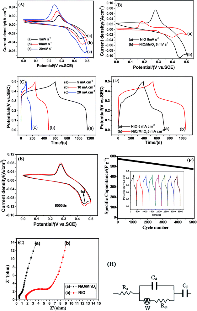
Hierarchical MnO2 nanosheets attached on hollow NiO microspheres have been designed by a facile hydrothermal process. The core–shell structure is achieved by decorating an MnO2 nanosheet shell on a hollow NiO sphere core. The highly hollow and porous structure exhibits a high surface area, shortened ion diffusion length, outstanding electrochemical properties (558 F g−1 at a current density of 5 mA cm−2), and excellent cycling stability (83% retention after 5000 cycles). To further evaluate the NiO/MnO2 core–shell composite electrode for real applications, three asymmetric supercapacitors (NiO/MnO2//pomelo peel (PPC), NiO/MnO2//buckwheat hull (BHC), and NiO/MnO2//activated carbon (AC)) are assembled. The results demonstrated that NiO/MnO2//BHC delivered a substantial energy density (20.37 W h kg−1 at a power density of 133.3 W kg−1) and high cycling stability (88% retention after 5000 cycles) within a broad operating potential window of 1.6 V.
1. Introduction
Owing to energy depletion, energy storage has become a key technological challenge in the 21st century. Among various emerging energy storage technologies, supercapacitors have attracted great research interest owing to their advantages and potential applications.1–4 According to the energy storage mechanism, supercapacitors can be classified into two types: electric double-layer capacitors (EDLC) and Faraday pseudocapacitors. Recently, owing to the rapid reversible redox reaction, the specific capacitance has become larger. So, pseudocapacitors are studied by many researchers. Pseudocapacitors can be classified into symmetrical and asymmetric supercapacitors according to the way the positive and negative electrodes store energy. Asymmetric supercapacitors have attracted increasing amounts of attention because they can achieve the highest voltage window of the devices. Generally, transition metal oxides are used as cathodes and carbon materials are used as anodes for asymmetric supercapacitors.As is well known, electrode materials play a key role in improving the electrochemical properties of the supercapacitors. Transition metal oxides are of special interest owing to their different oxidation states, which play a vital role in the effective transfer of redox charge. Ruthenium oxide (RuO2) has shown excellent capacitive properties as a supercapacitor electrode with a capacitance as high as 1300 F g−1,5 but the high production cost limits its wide application. The applications of cheap metal oxides (such as Fe2O3,6 MnO2,7 Co3O4,8 and NiO9) have been widely researched. However, in their application in supercapacitors, each material has its own advantages and disadvantages. NiO is considered to be the most promising supercapacitor electrode material and it exhibits many unique properties. However, low ion insertion/release at the electrode/electrolyte interface limits its application.10 Owing to its wide operating potential window and high theoretical capacity, MnO2 has received increasing amounts of research attention. However, its disadvantages are its low surface area and poor electrical conductivity.11,12 In order to utilize the benefits of metal oxides and overcome their disadvantages, an emerging attractive concept is to study metal oxide composites as electrode materials. For example, Zhao et al.13 prepared a porous composite of Mn2O3/C@Co3O4 by a facile two-step hydrothermal route. The composite showed superior reversible specific capacitance (523.8 F g−1 at a current density of 0.3 A g−1) and good cycling stability (90.6% retention after 3000 cycles). Wang et al.14 synthesized NiO@Co3O4@MnO2 particles via a three-step hydrothermal method. The particles had an excellent specific capacitance (792.5 F g−1 at a current density of 2 A g−1) and superior cycling stability (>90% capacity retention after 1000 cycles). Liu et al.15 fabricated a NiO/NiCo2O4/Co3O4 composite by a sol–gel method, which had a high specific surface area and a mesoporous structure. In addition, a large number of studies have shown that the fabricated composite exhibits high specific capacitance and excellent electrochemical stability.16–18 Carbon materials (carbon,19 graphene aerogel,20 graphene,21 biochar,22 etc.) are widely used as anode materials in asymmetric supercapacitors. Among them, biochar is attracting growing attention due to its environmental friendliness, low cost and extensive sources.
In the present work, the NiO/MnO2 core–shell composite is prepared by a facile method, and the core–shell composite is formed of a MnO2 nanosheet shell and a hollow NiO sphere core. Research shows that a nanosheet shell decorated on a hollow sphere core can provide highly hollow and porous structures, which can shorten the ion diffusion length and exhibit a high surface area.23–25 This structural feature is in favour of increasing the electrochemical performance. Furthermore, asymmetric supercapacitors based on a core–shell NiO/MnO2 cathode and a biochar anode are assembled (Scheme 1). Two types of biochar (pomelo peel (PPC) and buckwheat hull (BHC)) are processed. For comparison, three asymmetric supercapacitors (NiO/MnO2//PPC, NiO/MnO2//BHC, and NiO/MnO2//AC) are assembled. The results demonstrated that NiO/MnO2//BHC delivered substantial energy density (20.37 W h kg−1 at a power density of 133.3 W kg−1), and excellent cycling stability (88% capacitance retention after 5000 cycles).
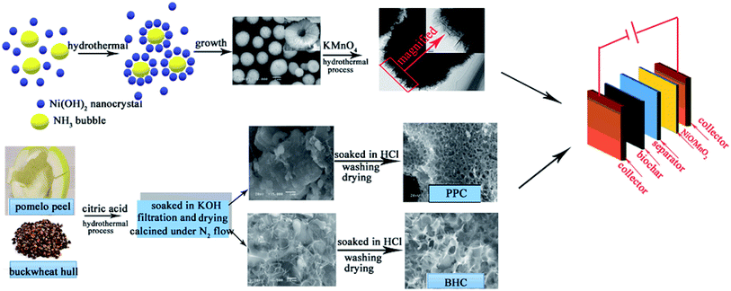 | ||
| Scheme 1 Preparation process for the asymmetric supercapacitor device based on a core–shell NiO/MnO2 cathode and biochar anode. | ||
2. Experimental
2.1 Preparation of NiO/MnO2 core–shell composites
The NiO/MnO2 nanocomposite was prepared in two steps. First of all, the hollow NiO nanospheres were synthesized by a facile hydrothermal route.26–28 In a typical process, 2.0 g of Na2SO4 salt, 2.0 g of glycine, and 5.0 mmol of Ni(NO3)2·6H2O were dissolved in 25 mL of deionized water. 10 mL of a NaOH solution was gradually dropped into the above solution by syringe pump. The solution was then shifted to a 40 mL Teflon-lined autoclave and kept at 170 °C for 24 hours. Under ultrasonication, the samples were washed with deionized water several times and then dried at 60 °C. After that, the precursors were converted to NiO hollow spheres by calcining at 400 °C for 2 hours. Then the growth of the MnO2 shell was studied using the NiO hollow spheres as the skeleton.Secondly, 4.0 g of NiO hollow spheres were dissolved in 40 mL of 0.02 mol L−1 potassium permanganate (KMnO4) under vigorous magnetic stirring, and then transferred into a 50 mL Teflon-lined autoclave and kept at 120 °C for 12 h. Under ultrasonication, the samples were washed several times with deionized water and then dried at 60 °C for 6 h. The final product was denoted as the NiO/MnO2 core–shell composite.
2.2 Preparation of PPC and BHC
The pomelo peel was cut into small pieces and then dried to constant weight at 60 °C. Then, 5 g of pomelo peel was immersed in 0.1 M citric acid, then heated to 200 °C and maintained for 6 h in a 100 mL Teflon-lined stainless steel autoclave.After washing and drying, the sample was soaked in 40 mL of 4 M KOH solution for 12 h. After filtration and drying, the sample was heated to 350 °C (heating rate: 5 °C per minute) and held at that temperature for 0.5 h, heated up to 550 °C (heating rate: 5 °C per minute) and held for 0.5 h, and heated up to 700 °C (heating rate: 5 °C per minute) and held for 2 h under N2 flow in a tubular oven. Finally, the activated samples were dipped in 1 M HCl solution and then washed with deionized water several times. The obtained sample was marked as PPC.
Using the same synthesis method, BHC was obtained.
AC was provided by Changchun Industrial Activated Carbon Co. Ltd.
2.3 Material characterization
The phase composition and crystal structure of the electrode materials were characterized by powder X-ray diffraction (XRD), which was conducted on a Rigaku D/max-IIIB diffractometer with the following test conditions: Cu Kα as the X-ray source, wavelength of 0.15405 nm, and scanning speed of 10° min−1. Scanning electron microscopy (SEM) was carried out using a Hitachi S-4800 with the following test conditions: working voltage of 10 kV and work distance of 12 mm. Transmission electron microscopy (TEM) was carried out using an FEI Tecnai G2 S-Twin. Nitrogen adsorption–desorption measurements (BET method) were performed at liquid nitrogen temperature with an ASAP 2010 apparatus from Micromeritics.2.4 Electrochemical tests
The working electrodes were fabricated by mixing 10 mg of the NiO/MnO2 core–shell composite with 1.33 mg of acetylene black, 1.33 mg of graphite and two drops of polytetrafluoroethylene (PTFE). A drop of ethanol was added to the above mixture to form a homogeneous paste with the assistance of ultrasonication. The above homogeneous paste was then coated on a nickel foam substrate (1 × 1 cm).A three-electrode electrochemical cell was used to investigate the electrochemical properties of the as-obtained samples. The as-prepared NiO/MnO2 composite was used as the working electrode, a saturated calomel electrode (SCE) was used as the reference electrode and platinum foil (1 × 1 cm) was used as the counter electrode. 6.0 M KOH aqueous solution was used as the electrolyte. Cyclic voltammograms, galvanostatic charge/discharge curves, and electrochemical impedance spectroscopy (EIS) were employed to inspect the electrochemical performance of the NiO/MnO2 core–shell composite using a CHI 660D electrochemical workstation. Cyclic voltammetry (CV) curves were conducted at scan rates of 3, 5, and 10 mV s−1 and the voltage range was from 0 to 0.5 V (vs. SCE). Galvanostatic charge/discharge tests were carried out at different current densities (5, 10, and 20 mA cm−2) in the voltage range from 0 to 0.5 V (vs. SCE). EIS measurements were also taken in the frequency range from 100 kHz to 0.005 Hz.
The preparation process used for the working electrodes of the two kinds of biomass carbon (PPC and BHC) is the same as that for the NiO/MnO2 core–shell composite.
Three asymmetric supercapacitors (NiO/MnO2//PPC, NiO/MnO2//BHC, and NiO/MnO2//AC) were assembled. According to charge balance theory,29 the mass ratios of the positive and negative electrodes of NiO/MnO2//PPC, NiO/MnO2//BHC, and NiO/MnO2//AC were fixed at 1![[thin space (1/6-em)]](https://www.rsc.org/images/entities/char_2009.gif) :
:![[thin space (1/6-em)]](https://www.rsc.org/images/entities/char_2009.gif) 3, 1
3, 1![[thin space (1/6-em)]](https://www.rsc.org/images/entities/char_2009.gif) :
:![[thin space (1/6-em)]](https://www.rsc.org/images/entities/char_2009.gif) 2, and 1
2, and 1![[thin space (1/6-em)]](https://www.rsc.org/images/entities/char_2009.gif) :
:![[thin space (1/6-em)]](https://www.rsc.org/images/entities/char_2009.gif) 4, respectively.
4, respectively.
3. Results and discussion
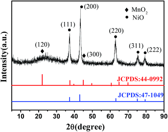
Fig. 1 shows the XRD pattern of the NiO/MnO2 core–shell composite. The cubic MnO2 phase (JCPDS: 44-0992) diffraction peaks and the cubic NiO phase (JCPDS: 47-1049) diffraction peaks30 indicate that the NiO/MnO2 composite has been formed.Fig. 2 presents the nitrogen adsorption–desorption isotherm of the NiO hollow spheres and the NiO/MnO2 core–shell composite. Both of the materials display type IV isotherms, which are representative of mesoporous materials according to the IUPAC classification. The surface areas of the NiO hollow spheres and the NiO/MnO2 core–shell composite calculated using a multipoint BET model are 63 m2 g−1 and 89 m2 g−1, respectively.
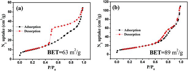 | ||
| Fig. 2 Nitrogen adsorption–desorption isotherm of hollow NiO spheres (a). Nitrogen adsorption–desorption isotherm of the NiO/MnO2 core–shell nanocomposite (b). | ||
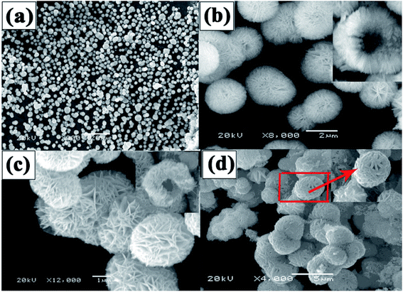
The SEM image of the Ni(OH)2 sample (Fig. 3(a)) indicates that the particle size, ranging from 3 to 5 μm in diameter, is uniform. A hollow structure can be observed at higher magnification (Fig. 3(b)), and the sample is composed of many NiO nanosheets, which facilitate rapid ion/electron transport. After being calcined at 400 °C (Fig. 3(c)), the diameter was reduced by 2–4 μm, and the spheres still have a hollow structure. However, because the wall of the spheres is too thick, the hollow structure cannot be found in the TEM image (Fig. 4(a)), but the image shows that the surface of the hollow NiO spheres is smooth. For the NiO/MnO2 core–shell composite (Fig. 3(d)), the MnO2 nanosheet shells can be seen on the hollow NiO sphere cores, and the MnO2 nanosheets are interlinked with lengths up to 100 nm. This structure makes the composite more closely arranged and the small gaps in the composite can provide channels for electrolyte insertion and extraction. Finally, full use can be made of the effective area of the active material. The TEM image (Fig. 4(b)) further confirms that thin MnO2 nanosheets uniformly grew on the surface of the hollow NiO spheres. HRTEM (Fig. 4(c)) was performed to further elucidate the surface plane of the NiO/MnO2 core–shell composite. In Fig. 4(c), the lattice fringes can be observed. However, the lattice structure of MnO2 (d(120) = 0.28 nm) is not obvious, which may be caused by its poor crystal shape, which is consistent with the XRD results. The lattice fringe corresponding to the (200) (d = 0.20 nm) crystallographic plane of NiO is shown.
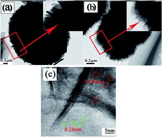 | ||
| Fig. 4 (a) TEM image of NiO after being annealed at 400 °C. (b) TEM image of the NiO/MnO2 core–shell composite. (c) HRTEM image of the NiO/MnO2 core–shell composite. | ||
Fig. 5 exhibits EDS images of the NiO/MnO2 core–shell composite. O, Ni, Mn and K elements are observed. K element is from the raw material KMnO4. The mass percentages of O, Ni and Mn are 30.7%, 14.20% and 20.31%, respectively. Fig. 5(d)–(f) present the EDS mapping for the NiO/MnO2 core–shell composite, showing the distribution of elements Ni, Mn, and O.
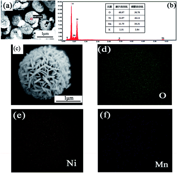 | ||
| Fig. 5 (a and b) EDS image of NiO/MnO2 core/shell composites; (c) SEM image of NiO/MnO2 core/shell composites; (d–f) elemental mappings of O, Ni and Mn elements. | ||
Fig. 6(A) shows the CV curves of the NiO/MnO2 core–shell composite at different scan rates ranging from 5 to 20 mV s−1. All the CV curves have similar shapes, and these shapes indicate that the capacitance characteristic is different from that of traditional electric double-layer capacitance. As the scan rate increases, the current increases subsequently. This indicates that NiO/MnO2 core–shell composite has fast electron and ion diffusion rates. The specific capacitance of the electrode can be obtained from the following equation:31
 | (1) |
 | (2) |
| Sample | Specific capacitance | Working potential | Electrolyte | Energy density, power density | Supp. ref. |
|---|---|---|---|---|---|
| NiO@MnO2 core–shell structure | 766.8 F g−1 (10 A g−1) | 0–0.5 V vs. SCE | 2.0 M KOH | — | 35 |
| NiO@MnO2 core–shell nanocomposite | 266.7 F g−1 (0.5 A g−1) | 0–0.45 V vs. SCE | 2.0 M KOH | — | 36 |
| NiO/MnO2 core–shell nanoflakes | 241 mF cm−2 (1 mA cm−2) | 0–0.7 V vs. SCE | 1.0 M KOH | — | 37 |
| NiO/MnO2 core–shell composite | 528 F g−1 (1 mV s−1) | 0–0.5 V vs. Ag/AgCl | 1 M LiOH | — | 30 |
| NiO/MnO2 core–shell composite | 558 F g−1 (5 mA cm−2) | 0–0.5 V vs. SCE | 6.0 M KOH | 20.37 W h kg−1, 133.3 W kg−1 | This work |
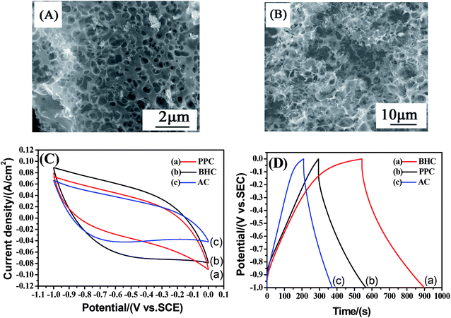
In order to further determine the morphologies and properties of different biochar, the SEM images and electrochemical properties are shown in Fig. 7. It can be seen that there are a large number of pores in the PPC (Fig. 7(A)) and BHC (Fig. 7(B)). However, the channels in the BHC are connected, while the channels in PPC are closed. The rapid diffusion of electrolyte ions and the fast transfer of electrons are attributed to this highly connected structure. CV curves of the different samples (PPC, BHC and AC) are shown in Fig. 7(C). A nearly rectangular shaped loop can be observed, which indicates that the materials have typical and ideal capacitive behaviors.22 As is known, the capacitance of the electrode material is directly proportional to the area it encloses, so according to eqn (1), BHC has the highest specific capacitance. The galvanostatic charge/discharge curves of the different samples (BHC, PPC and AC) are presented in Fig. 7(D). According to eqn (2), the specific capacitances of BHC, PPC and AC can be calculated to be 176.1 F g−1, 105.4 F g−1 and 83 F g−1, respectively. The results are in agreement with Fig. 7(C).
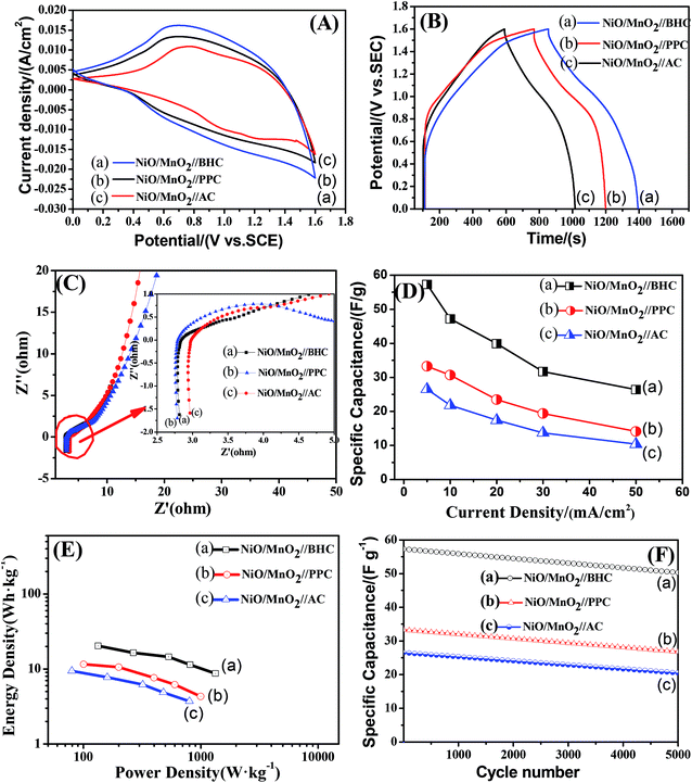
To further evaluate the electrochemical performance of the NiO/MnO2 core–shell composite electrode, a series of asymmetric supercapacitor devices using the NiO/MnO2 core–shell composite electrode as the cathode and biochar as the anode are assembled. The CV curves of the different supercapacitors are shown in Fig. 8(A). According to eqn (1), NiO/MnO2//BHC has the highest current response and the largest integral area according to its highest specific capacitance. Galvanostatic charge/discharge curves of NiO/MnO2//PPC, NiO/MnO2//BHC, and NiO/MnO2//AC are exhibited in Fig. 8(B). According to eqn (2) (where m is the total weight of the negative and positive electrode materials), the specific capacitances of NiO/MnO2//BHC, NiO/MnO2//PPC, and NiO/MnO2//AC can be calculated to be 57.3 F g−1, 33.3 F g−1 and 26.5 F g−1, respectively. The results indicate that the electrode material of NiO/MnO2//BHC not only provides a large surface area for charge storage but also promotes efficient electrolyte/electrode contact and the specific capacitance is improved. The EIS of the different supercapacitors are demonstrated in Fig. 8(C). It can be seen that the three supercapacitors have different solution resistances (Rs, x-intercept), and the Rs of NiO/MnO2//BHC, NiO/MnO2//PPC and NiO/MnO2//AC are 2.8 Ω, 2.78 Ω and 3.0 Ω, respectively. Furthermore, the charge transfer resistances (Rct, the diameter of the semicircles) of NiO/MnO2//BHC, NiO/MnO2//PPC and NiO/MnO2//AC can be calculated to be 0.7 Ω, 1.3 Ω and 1.1 Ω, respectively. The specific capacitances of the different supercapacitors at different current densities are shown in Fig. 8(D). It can be seen that NiO/MnO2//BHC has the highest rate capability and the highest specific capacitance. In order to further evaluate the electrochemical properties, Ragone curves (Fig. 8(E)) are demonstrated. According to eqn (3) and (4),38,39 the power density of NiO/MnO2//BHC is calculated to be 133.3 W kg−1 and the energy density is 20.37 W h kg−1. Furthermore, the energy density can still remain 13.55 W h kg−1 at a high power density of 810.33 W kg−1.
 | (3) |
 | (4) |
The cycling performance of the different supercapacitors is exhibited in Fig. 8(F). After 5000 cycles, the specific capacitances of NiO/MnO2//BHC, NiO/MnO2//PPC and NiO/MnO2//AC remained at 88%, 81% and 77% of their maximums, which shows that NiO/MnO2//BHC possesses excellent cycling stability and a long cycle life.
4. Conclusions
Hierarchical MnO2 nanosheets attached on hollow NiO microspheres have been fabricated by a facile hydrothermal method. The core–shell structure is achieved by decorating MnO2 nanosheets on NiO hollow spheres. Batch experiments were conducted to examine the electrochemical properties. The results indicated that the NiO/MnO2 composite exhibits outstanding electrochemical properties (558 F g−1 at a current density of 5 mA cm−2) and excellent cycling stability (83% capacitance retention after 5000 cycles). For comparison, three asymmetric supercapacitors (NiO/MnO2//pomelo peel (PPC), NiO/MnO2//buckwheat hull (BHC), and NiO/MnO2//AC) were assembled. The results demonstrated that NiO/MnO2//BHC delivered substantial energy density (20.37 W h kg−1 at a power density of 133.3 W kg−1) and high long-term stability (88% capacitance retention after 5000 cycles) within a broad operating potential window of 1.6 V.Conflicts of interest
There are no conflicts to declare.Acknowledgements
This work was supported by the Department of Education of Jilin province “13th Five Year” science and technology research projects JJKH20180541KJ, the Jilin Engineering Normal University PhD startup foundation BSKJ201819 and the Jilin Engineering Normal University PhD startup foundation BSKJ201838.References
- J. R. Miller, R. A. Outlaw and B. C. Holloway, Graphene double-layer capacitor with ac line-filtering performance, Science, 2010, 329, 1637–1639 CrossRef CAS PubMed
.
- S. Sarangapani, B. V. Tilak and C. P. Chen, Materials for electrochemical capacitors, J. Am. Chem. Soc., 1996, 143, 3791–3799 CAS
.
- H. G. Li, A. F. Liu and H. W. Che, Synthesis of hierarchical Cu2O octahedra@Ni(OH)2 nanosheets core-shell heterostructures for high-performance supercapacitor, Mater. Sci. Semicond. Process., 2019, 91, 115–123 CrossRef CAS
.
- P. C. Chen, G. Z. Shen, Y. Shi, H. T. Chen and C. W. Zhou, Preparation and characterization of flexible asymmetric supercapacitors based on transition-metal-oxide nanowire/single-walled carbon nanotube hybrid thin-film electrodes, ACS Nano, 2010, 4, 4403–4411 CrossRef CAS PubMed
.
- C. C. Hu, K. H. Chang, M. C. Lin and Y. T. Wu, Design and tailoring of the nanotubular arrayed architecture of hydrous RuO2 for next generation supercapacitors, Nano Lett., 2006, 6, 2690–2695 CrossRef CAS PubMed
.
- M. Serrapede, A. Rafique, M. Fontana, A. Zine, P. Rivolo, S. Bianco, L. Chetibi, E. Tresso and A. Lamberti, Fiber-shaped asymmetric supercapacitor exploiting rGO/Fe2O3 aerogel and electrodeposited MnOx nanosheets on carbon fibers, Carbon, 2019, 144, 91–100 CrossRef CAS
.
- X. Zhao, L. Zhang, S. Murali, M. D. Stoller, Q. Zhang, Y. Zhu and R. S. Ruoff, Incorporation of Manganese Dioxide within Ultraporous Activated Graphene for High-Performance Electrochemical Capacitors, ACS Nano, 2012, 6, 5404–5412 CrossRef CAS PubMed
.
- J. F. Ning, T. Y. Zhang, Y. He, C. P. Jia, P. Saha and Q. L. Cheng, Co3O4@CoS Core–Shell Nanosheets on Carbon Cloth for High Performance Supercapacitor Electrodes, Materials, 2017, 10, 608 CrossRef PubMed
.
- J. S. Zhao, Y. Tian, A. F. Liu, L. Song and Z. S. Zhao, The NiO electrode materials in electrochemical capacitor: A review, Mater. Sci. Semicond. Process., 2019, 96, 78–90 CrossRef CAS
.
- G. X. Pan, X. H. Xia, F. Cao, P. S. Tang and H. F. Chen, Fabrication of porous Co/NiO core/shell nanowire arrays for electrochemical capacitor application, Electrochem. Commun., 2013, 34, 146–149 CrossRef CAS
.
- Y. X. Zhang, M. Huang, F. Li, X. L. Wang and Z. Q. Wen, One-pot synthesis of hierarchical MnO2-modified diatomites for electrochemical capacitor electrodes, J. Power Sources, 2014, 246, 449–456 CrossRef CAS
.
- J. Zhao, Z. Lu, M. Shao, D. Yan, M. Wei, D. G. Evans and X. Duan, Flexible hierarchical nanocomposites based on MnO2 nanowires/CoAl hydrotalcite/carbon fibers for high-performance supercapacitors, RSC Adv., 2013, 3, 1045–1049 RSC
.
- J. Zhao, Y. Li, Z. Y. Xu, D. W. Wang, C. L. Ban and H. H. Zhang, Unique porous Mn2O3/C cube decorated by Co3O4 nanoparticle: Lowcost and high-performance electrode materials for asymmetric supercapacitors, Electrochim. Acta, 2018, 289, 72–81 CrossRef CAS
.
- H. Wang, Q. Ren, D. J. L. Brett, G. J. He, R. F. Wang, J. L. Key and S. Ji, Double-shelled tremella-like NiO@Co3O4@MnO2 as a highperformance cathode material for alkaline supercapacitors, J. Power Sources, 2017, 343, 76–82 CrossRef CAS
.
- M. C. Liu, L. B. Kong, C. Lu, X. M. Li, Y. C. Luo and L. Kang, A Sol–Gel Process for Fabrication of NiO/NiCo2O4/Co3O4 Composite with Improved Electrochemical Behavior for Electrochemical Capacitors, ACS Appl. Mater. Interfaces, 2012, 4, 4631–4636 CrossRef CAS PubMed
.
- Y. H. Li, H. R. Peng, C. Zhang, M. S. Chu, P. Xiao and Y. H. Zhang, Branched ultra-fine nickel oxide/manganese dioxide core-shell nanosheet arrays for electrochemical capacitor, RSC Adv., 2015, 5, 77115–77121 RSC
.
- J. J. Chen, Y. Huang, C. Li, X. F. Chen and X. Zhang, Synthesis of NiO@MnO2 core/shell nanocomposites for supercapacitor application, Appl. Surf. Sci., 2015, 10, 187 Search PubMed
.
- X. L. Guo, M. Kuang, F. Dong and Y. X. Zhang, Monodispersed plumcandy-like MnO2 nanosheets-decorated NiO nanostructures for supercapacitors, Ceram. Int., 2016, 42, 7787–7792 CrossRef CAS
.
- H. D. Jiang, X. K. Ye, Y. C. Zhu, L. L. Wang, P. Zhao, Z. Y. Yue, J. L. Xie, Z. Q. Wan and C. Y. Jia, Toward high-rate supercapacitor: Preparation of hierarchical porous carbon binder-free electrode with controllable texture, Appl. Surf. Sci., 2019, 470, 573–580 CrossRef CAS
.
- X. W. Xu, Y. Liu, P. Dong, P. M. Ajayan, J. F. Shen and M. X. Ye, Mesostructured CuCo2S4/CuCo2O4 nanoflowers as advanced electrodes for asymmetric supercapacitors, J. Power Sources, 2018, 400, 96–103 CrossRef CAS
.
- Y. Ouyang, R. J. Huang, X. F. Xia, H. T. Ye, X. Y. Jiao, L. Wang, L. Wu and Q. L. Hao, Hierarchical structure electrodes of NiO ultrathin nanosheets anchored to NiCo2O4 on carbon cloth with excellent cycle stability for asymmetric supercapacitors, Chem. Eng. J., 2019, 355, 416–427 CrossRef CAS
.
- G. Qu, S. F. Jia, H. Wang, F. Cao, L. Li, C. Qing, D. M. Sun, B. X. Wang, Y. W. Tang and J. B. Wang, Asymmetric Supercapacitor Based on Porous N-doped Carbon Derived from Pomelo Peel and NiO Arrays, ACS Appl. Mater. Interfaces, 2018, 8, 20822–20830 CrossRef PubMed
.
- L. L. Lai, W. Wen and J. M. Wu, Hierarchical nanosheet assembled yolk-shell TiO2 microspheres with improved photocatalytic activity, CrystEngComm, 2016, 18, 5195–5203 RSC
.
- S. H. Liu, S. N. Li, K. Sekar, R. Li, Y. Y. Zhu, R. M. Xing, K. Nakata and A. Fujishim, Hierarchical ZnS@C@MoS2 core-shell nanostructures as efficient hydrogen evolution electrocatalyst for alkaline water electrolysis, Int. J. Hydrogen Energy, 2019, 44, 25310–25318 CrossRef CAS
.
- H. Wang, Q. Ren, D. J. L. Brett, G. J. He, R. F. Wang, J. L. Key and S. Ji, Double-shelled tremella-like NiO@Co3O4@MnO2 as a high performance cathode material for alkaline supercapacitors, J. Power Sources, 2017, 343, 76–82 CrossRef CAS
.
- J. Liu, S. Du, L. Wei, H. Liu, Y. Tian and Y. Chen, Template-free synthesis of NiO hollow microspheres covered with nanoflakes, Mater. Lett., 2006, 60, 3601–3604 CrossRef CAS
.
- Y. Wang, Q. Zhu and H. Zhang, Fabrication of β-Ni(OH)2 and NiO hollow spheres by a facile template-free process, Chem. Commun., 2005, 48, 5231–5233 RSC
.
- D. Xie, W. Yuan, Z. Dong, Q. Su, J. Zhang and G. Du, Facile synthesis of porous NiO hollow microspheres and its electrochemical lithium-storage performance, Electrochim. Acta, 2013, 92, 87–92 CrossRef CAS
.
- Z. S. Wu, W. C. Ren, D. W. Wang, F. Li, B. L. Liu and H. M. Cheng, High-Energy MnO2 Nanowire/Graphene and Graphene Asymmetric Electrochemical Capacitors, ACS Nano, 2010, 4, 5835–5842 CrossRef CAS PubMed
.
- B. J. Zhang, W. Y. Li, J. Q. Sun, G. J. He, R. J. Zou, J. Q. Hu and Z. G. Chen, NiO/MnO2 core/shell nanocomposites for high-performance pseudocapacitors, Mater. Lett., 2014, 114, 40–43 CrossRef CAS
.
- X. F. Lu, T. K. Zhao, X. L. Ji, J. Hu and T. Li, 3D printing well organized porous iron-nickel/polyaniline nanocages multiscale supercapacitor, J. Alloys Compd., 2018, 760, 78–83 CrossRef CAS
.
- Y. C. Tsai, W. D. Yang, K. C. Lee and C. M. Huang, An Effective Electrodeposition Mode for Porous MnO2/Ni Foam Composite for Asymmetric Supercapacitors, Materials, 2016, 9, 246 CrossRef PubMed
.
- C. Yuan, X. Zhang, Q. Wu and B. Gao, Effect of temperature on the hybrid supercapacitor based on NiO and activated carbon with alkaline polymer gel electrolyte, Solid State Ionics, 2006, 177, 1237–1242 CrossRef CAS
.
- J. W. Lee, T. Ahn, J. H. Kim, J. M. Ko and J. D. Kim, Nanosheets based mesoporous NiO microspherical structures via facile and template-free method for high performance supercapacitors, Electrochim. Acta, 2011, 56, 4849–4857 CrossRef CAS
.
- T. F. Yi, J. Mei, B. Guan, P. Cui, S. Luo, Y. Xie and Y. Liu, Construction of spherical NiO@MnO2 with core-shell structure obtained by depositing MnO2 nanoparticles on NiO nanosheets for high-performance supercapacitor, Ceram. Int., 2020, 46, 421–429 CrossRef CAS
.
- J. Chen, Y. Huang, C. Li, X. Chen and X. Zhang, Synthesis of NiO@MnO2 core/shell nanocomposites for supercapacitor application, Appl. Surf. Sci., 2016, 360, 534–539 CrossRef CAS
.
- S. Xi, Y. Zhu, Y. Yang, S. Jiang and Z. Tang, Facile Synthesis of Free-Standing NiO/MnO2 Core-Shell Nanoflakes on Carbon Cloth for Flexible Supercapacitors, Nanoscale Res. Lett., 2017, 12, 171–180 CrossRef PubMed
.
- Y. Zhou, L. Ma, M. Y. Gan, M. H. Ye, X. R. Li, Y. F. Zhai, F. B. Yan and F. F. Cao, Monodisperse MnO2@NiCo2O4 core/shell nanospheres with highly opened structures as electrode materials for good-performance supercapacitors, Appl. Surf. Sci., 2018, 444, 1–9 CrossRef CAS
.
- W. D. He, C. G. Wang, H. Q. Li, X. L. Deng, X. J. Xu and T. Y. Zhai, Ultrathin and Porous Ni3S2/CoNi2S4 3D-Network Structure for Superhigh Energy Density Asymmetric Supercapacitors, Adv. Energy Mater., 2017, 21, 1700983 CrossRef
.
| This journal is © The Royal Society of Chemistry 2019 |

