Three dimensional composites of graphene as supports in Pd-catalyzed synthetic applications†
Yuan
Yang
 a,
Stanly E.
Gilliland
III
a,
Sajjad
Ghobadi
a,
Michael
Burkholder
a,
Sarah E.
Smith
a,
B. Frank
Gupton
*a and
Carlos E.
Castano
a,
Stanly E.
Gilliland
III
a,
Sajjad
Ghobadi
a,
Michael
Burkholder
a,
Sarah E.
Smith
a,
B. Frank
Gupton
*a and
Carlos E.
Castano
 *b
*b
aDepartment of Chemical and Life Science Engineering, Virginia Commonwealth University, 23284, Richmond, Virginia, USA. E-mail: bfgupton@vcu.edu
bDepartment of Mechanical and Nuclear Engineering, Virginia Commonwealth University, 23284, Richmond, Virginia, USA. E-mail: cecastanolond@vcu.edu
First published on 7th November 2018
Abstract
The graphitic one-dimensional carbon nanotube (CNT) and two-dimensional graphene (G) are important support materials in heterogeneous catalysis. However, the production of highly active but stable and recyclable catalysts using these materials is still challenging. In this work, through a facile and solventless method, a 3D composite was prepared by growing multiwall CNTs on G nanoplatelets through the Ni-catalyzed “tip growth” mechanism using a combination of ball milling and microwave irradiation steps. The advantageous high surface area provided by the atomically thin sheet of G and the aspect ratio of the CNT are combined to retain and enhance the mechanical, electronic, thermal, and catalytic properties. The resulting 3D Ni–graphene–carbon nanotube hybrid (NiGCNT) material exhibits magnetic properties and the unique 3D structure prevents graphene sheet restacking facilitating better catalyst recyclability and longevity. The exceptional catalytic properties provided by this 3D NiGCNT support loaded with Pd nanoparticles were demonstrated and tested in both Suzuki cross-coupling and C–H activation reactions. The Pd–NiGCNT was 10 times more active than commercially available Pd on activated carbon catalysts.
Introduction
The increasing demands for both efficient and environmentally benign chemical processes have stimulated the development of heterogeneous catalysis in the fine chemical, energy and pharmaceutical industries.1–3 Heterogeneous catalysts can overcome many disadvantages of homogeneous catalysts related to cost as well as metal contamination and recyclability. The selection of the support for a heterogeneous catalyst is critical and has traditionally served only as a means to immobilize the catalyst.1,3–6 Graphene is a two-dimensional carbon allotrope that has been extensively exploited as a heterogeneous catalyst support material due to its high specific area, high conductivity, and excellent thermal and chemical stability.7,8 Recently, researchers have demonstrated that graphene supports are actively assisting in the charge transfer between the supported metal particles and the adsorbed molecules in many reactions such as cross-coupling, arylation, hydrogenation, and oxidation reactions due to the conductive nature of the sp2 hybridized carbon.9–12 However, one issue that has not been properly addressed and limits the full potential of the graphene-based catalysts is the tendency of graphene sheets to restack which leads to decreased surface area, diminished access to catalyst trapped between sheets, limited recyclability of the catalyst, and poor reaction reproducibility.13–15Considerable efforts have been made to address the restacking issue of graphene.16,17 One intriguing approach is to integrate the one-dimensional carbon nanotube (CNT) and the two-dimensional graphene into a three-dimensional (3D) composite.18 In doing so, this combines the advantages of the high surface area provided by the atomic thin sheet of graphene and the high aspect ratio of the CNTs.16,19,20 Additionally, experimental results also suggest that the hybrid 3D composite possess enhanced electrical properties, reduced sheet resistance, modified mechanical and thermal properties, and superior electrochemical stability when the CNTs are seamlessly attached to the graphene lattice.14,18,21–23 Unfortunately, previous production of CNTs and graphene has relied on chemical vapor deposition (CVD) methods which are typically not efficient with respect to cost or throughput and require an additional carbon source;24 the specialized equipment used in CVD reactions alone is a significant cost inhibitor from the adoption of these processes commercially. Moreover, the use of additional carbon source, such as methylene, ethylene and alcohols, will generate stoichiometric amount of H and O elements waste.25 A method to synthesize the GCNT materials that is facile, low-cost, rapid, and easy to scale up is highly desired.14,24
Ball milling has been used to engineer the surface of graphene and graphite.26–29 For example, ball milling was used to mechanically exfoliate graphite and functionalize graphene by adding impurities to the edge of the lattice.27,30,31 The Brunauer–Emmett–Teller (BET) surface area of graphite 10 m2 g−1 was reported to increase up to 150–450 m2 g−1 after the exfoliation.28,30,32 Heteroatoms and nanoparticles, such as Ni, can also be added to graphene through the ball milling process which breaks the strong interaction between graphene lattices and results in a new surface that is chemically active.27,33 Microwave irradiation has also been used to engineer graphene. Previously, microwave irradiation has been utilized to remove functional groups on graphene,34 to generate defected sites on graphene,35 and to deposit heteroatoms and nanoparticles on graphene.10,36 Researchers have demonstrated the growth of CNT via microwave irradiation of Ni when in the presence of an added carbon source through a Ni-catalyzed “tip-growth” method.14 We hypothesize that ball milling can be used to first load Ni nanoparticles on to graphene and then microwave irradiation can be utilized to reduce the Ni nanoparticle in situ and grow CNTs on graphene by directly consuming graphene as the carbon source to produce a Ni–graphene–CNT hybrid material which would prevent graphene restacking issues and enhance the mechanic properties due to the formation of the network of the CNTs.
Herein, an innovative, cost-effective, scalable, and rapid approach to synthesize magnetic 3D Ni–graphene–carbon nanotube (NiGCNT) hybrid catalyst support material is developed and then tested for enhanced catalytic properties in Suzuki cross-coupling and C–H activation reactions following functionalization with Pd nanoparticles (Pd/NiGCNT). Pd nanoparticles were immobilized on the 3D NiGCNT support through various methods including an additional ball milling treatment or a microwave-assisted chemical reduction. The resulting materials exhibited highly robust catalytic activity for cross-coupling and C–H activation reactions and were easily recycled.
Materials and methods
Synthesis of Ni–graphene–carbon nanotubes (NiGCNT) from graphene nanoplatelets (GNP)
Nickel(II) acetylacetonate (220 mg, 0.84 mmol, 10 wt%, from Sigma Aldrich and used as-received) and graphene nanoplatelets (450 mg, sub-micron particles with a surface area of 500 m2 g−1) were placed in a ceramic vial (SPEX CertiPrep) with two ceramic balls d = 1.3 cm and milled for 45 minutes (SPEX CertiPrep 8000D high-energy shaker mill) to obtain Ni loaded on graphene (NiG). Then, 400 mg of the collected NiG material was placed in a 10 mL CEM microwave tube and heated for 60 min at 135 °C (CEM microwave reactor). The resulting NiGCNT material was washed using deionized water (18.2 MΩ cm) and dried at 100 °C for 24 hours.Functionalizing NiGCNT with Pd nanoparticles via co-reduction method (Pd/NiGCNT CO)
In a beaker, 90 mg of NiGCNT and 200 μL of 10 wt% palladium nitrate solution (0.1 mmol, 10 wt%) were added to 200 mL of deionized water (18.2 MΩ cm) and sonicated at 300 W for 20 minutes. Next, 400 μL of hydrazine hydrate (3 mmol) was slowly added under constant stirring. The solution was then irradiated in a conventional microwave oven (Emerson MW8119SB) operating at full power (1100 W, 2.45 GHz) for 2 minutes. The product was washed using deionized water (18.2 MΩ cm) and dried overnight under vacuum at 80 °C.Functionalizing NiGCNT with Pd nanoparticles via ball milling method (Pd/NiCGNT BM)
In a ceramic vial (SPEX CertiPrep) with two ceramic balls (d = 1.3 cm), 105 mg of palladium acetate (0.42 mmol, 10 wt%) and 450 mg of the NiGCNT were milled for 45 minutes (SPEX CertiPrep 8000D high-energy shaker mill). The resulting mixture was washed using deionized water (18.2 MΩ cm) and dried at 100 °C for 24 hours. The Ni and Pd contents were then determined by inductively coupled plasma – optical emission spectrometry (ICP-OES), Agilent 5110 ICP-VCV-OES.Procedure for Suzuki cross-coupling reaction
For a typical cross-coupling reaction, 64 mg of 4-bromotoluene (0.32 mmol, 1 eq.) was dissolved in 4 mL H2O–EtOH (1![[thin space (1/6-em)]](https://www.rsc.org/images/entities/char_2009.gif) :
:![[thin space (1/6-em)]](https://www.rsc.org/images/entities/char_2009.gif) 1) in a 10 mL reaction vial. Next, 47 mg of phenylboronic acid (0.382 mmol, 1.2 eq.), and 133 mg of potassium carbonate (0.96 mmol, 3 eq.) were added to the solution. Then, 0.05 mol% of the catalyst was added to the vial which was then sealed, stirred, and heated at 80 °C. After 10 minutes, the mixture was diluted with 10 mL of EtOH and analyzed using GCMS and HPLC. The turnover frequency (TOF) was calculated using the GCMS relative peak area percentages (RPA%) at time points where RPA% conversion was approximately 60–80%. TOF = molar of product/(molar of Pd × reaction time). For this calculation, the total moles of Pd was considered for the total amount of Pd in the system.
1) in a 10 mL reaction vial. Next, 47 mg of phenylboronic acid (0.382 mmol, 1.2 eq.), and 133 mg of potassium carbonate (0.96 mmol, 3 eq.) were added to the solution. Then, 0.05 mol% of the catalyst was added to the vial which was then sealed, stirred, and heated at 80 °C. After 10 minutes, the mixture was diluted with 10 mL of EtOH and analyzed using GCMS and HPLC. The turnover frequency (TOF) was calculated using the GCMS relative peak area percentages (RPA%) at time points where RPA% conversion was approximately 60–80%. TOF = molar of product/(molar of Pd × reaction time). For this calculation, the total moles of Pd was considered for the total amount of Pd in the system.
Procedure for C–H activation reaction
C–H activation reaction was tested by adding 1.4 mg (0.5 mol%) of catalyst to 2.4 mL of methanol in a 5 mL vial and heating to 80 °C. Next, 40 mg of 8-methyl quinoline (0.28 mmol) and 180.4 mg of (diacetoxyiodo)benzene (0.56 mmol) were added to the vial, sealed and maintained at 80 °C for 15 minutes. The mixture was then diluted with 10 mL of EtOH and analyzed using GCMS and HPLC.Characterization of the catalyst materials
Powder X-ray diffraction (XRD) patterns were obtained on a PANalytical MPD X'Pert Pro (Cu Kα, λ = 1.54 Å) scanned from 20° to 80° 2-theta. The Scherrer equation was used to calculate the crystallite size from the diffraction peaks.37 Quantitative chemical analysis and chemical states were investigated with X-ray photoelectron spectroscopy (XPS) using a ThermoFisher ESCALAB 250. Survey and high-resolution photoelectron spectra were recorded with 1 eV and 0.1 eV steps, respectively. CASAXPS 2.3 16 V software and NIST Standard Reference Database 20, Version 4.1 were used to analyze and fit the XPS spectra. The magnetic analysis of the catalyst was carried out with a Quantum Design VersaLab vibrating sample magnetometer (VSM) from −3000 Oe to +3000 Oe at room temperature. Scanning electron microscopy (SEM) and scanning transmission electron microscopy (STEM) images were acquired using a Hitachi SU-70 FE-SEM at 5 kV and 30 kV, respectively. The BET surface and micropore area were tested by a Micromeritics ASAP 2020 Plus Physisorption system. Temperature programmed reduction (TPR) and pulse chemisorption experiments with H2 titration were conducted with the Micromeritics AutoChem II 2920 chemisorption analyzer to determine the number of active sites, metal dispersion, metallic surface area, and active particle size.Results and discussion
A method was developed to produce a 3D NiGCNT catalyst support material by combining graphene with CNTs to overcome graphene restacking issues and produce a support material capable of enhancing catalytic properties. Graphene nanoplatelets were chosen as the starting material and carbon source as they are an exceptionally cost-effective source of graphene (<$1 per g) and can be commercially produced in large quantities. Ni was deposited onto the GNP through ball milling and then CNTs were grown directly on the graphene material via solventless microwave irradiation. This enabled a simple, cost-effective, scalable, and rapid approach that eliminates complex and expensive steps to functionalize graphene with CNTs. The 3D NiGCNT can be easily functionalized with Pd nanoparticles through either a co-reduction (CO) or ball-milling (BM) process.Developing and investigating the synthesis of NiGCNT and Pd/NiGCNT
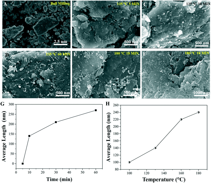
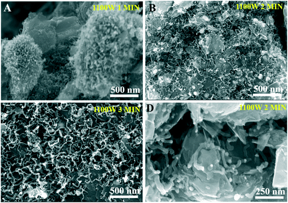
To elucidate the growth process of CNTs, the material at different stages of the NiGCNT synthesis and under various microwave irradiation conditions were first characterized using electron microscopy. As shown in Fig. 1A, no Ni nanoparticles and CNTs were observed following the ball milling process. The in situ formation of Ni nanoparticles and the Ni-induced growth of CNTs were observed only after the microwave irradiation treatment (Fig. 1B–E). The plots in Fig. 1F show the gradual increase of the length (from 100 ± 15 nm to ∼200 ± 25 nm) and diameter of the CNTs corresponding to increasing microwave irradiation time and temperature.The growth process was further intensified by using an 1100 W fixed power domestic microwave oven (Fig. 2 (A–D) and ESI† section S1). The average diameter and length of CNTs were increased to 39 nm and 400 nm, respectively after 3 min of microwave irradiation. It is important to note that due to the uneven heating generated by the domestic microwave, not all of the Ni nanoparticles had successfully induced the growth of the CNTs. Bare Ni nanoparticles deposited on graphene were observed after the microwave irradiation process, see ESI† Fig. S(2).
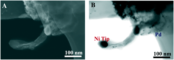
The Pd/NiGCNT synthesized via co-reduction (Pd/NiGCNT CO) were also characterized using STEM images. Fig. 3 demonstrates that Ni nanoparticles were mainly located at the tip of the CNTs which suggests the growth is proceeding through a “tip growth” mechanism. Small Pd nanoparticles (avg. 6 nm) were successfully deposited on the NiGCNT material. Both the graphene and CNTs in the NiGCNT were decorated with the Pd nanoparticles. This is beneficial as more surface area is utilized and the probability of agglomeration is reduced due to the proximity of neighboring nanoparticles. The Ni and Pd content of Pd/NiGCNT were then determined by ICP-OES. The Ni content was 6.4 wt% and 6.3 wt% for Pd/NiGCNT CO and Pd/NiGCNT BM, respectively. The Ni content was much lower than the nominal Ni content (10 wt%) even after 24 h of digestion in HCl. We attribute this difference to be caused by carbon coating and decoration of the Ni nanoparticles. The Pd content was 8.3 wt% and 8.6 wt% for Pd/NiGCNT CO and Pd/NiGCNT BM, respectively.
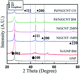
X-ray diffraction was used to further verify that Pd nanoparticles were loaded onto the 3D substrate. The GNP support only, Ni/GNP BM, NiGCNT 1 and 2 minutes, Pd/NiGCNT BM, and Pd/NiGCNT CO XRD spectra are shown in Fig. 4. The peaks corresponding to Ni planes (111), (200), and (220) are not observed immediately after the ball milling step which indicates that the Ni is not reduced to form crystalline nanoparticles during this process. Following the microwave treatment crystalline Ni peaks emerged and the crystallite size was calculated to be ∼33 nm after only one minute of microwave treatment (NiGCNT 1 min). Interestingly, the crystallite size of Ni is approximately the average diameter of the produced CNTs. The crystallite sizes of the Pd nanoparticles in Pd/NiGCNT BM and Pd/NiGCNT CO samples were 3.7 and 5.6 nm, respectively. The size of Pd nanoparticle of Pd/NiGCNT CO samples is slightly larger is believed to result from the using of strong reducing agent and high reduction temperature.
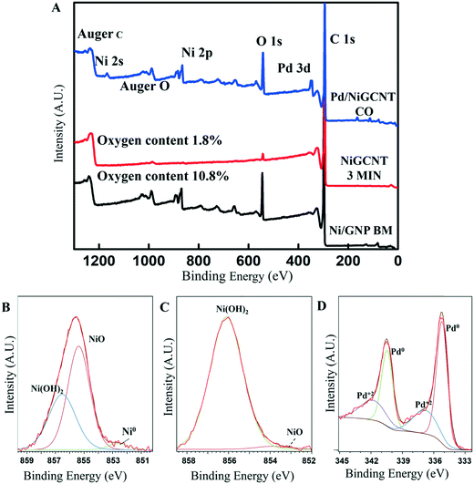
These materials were then analyzed with X-ray photoelectron spectroscopy to determine their elemental composition. From the XPS survey spectra shown in Fig. 5A, it was observed that the oxygen content dramatically decreased from 10.8 wt% to 1.8 wt% in Ni/GNP BM following 3 minutes of solventless microwave irradiation (NiGCNT 3 min). The solventless microwave irradiation has been previously shown to generate defect sites by the elimination of oxygen-containing functional groups on the graphene surface as CO or CO2.34 It is currently thought that metal nanoparticles simultaneously form and are strongly anchored by these defect sites and the Ni-catalyzed “tip-growth” of CNTs occurs. The Ni 2p peaks have strong intensity for Ni/GNP BM and Pd/NiGNCT CO samples. However, this peak intensity is almost negligible for NiGCNT 3 min sample. It is hypothesized that the reason for the decreased XPS signal of Ni is due to carbon decoration of Ni which results from the microwave irradiated removal of CO and CO2 depositing on the surface of Ni during the CNT growth process. The XPS survey of the Pd/NiGCNT CO material suggests that the Ni content is about 3.5 wt%, which is lower than the Ni content determined by ICP (6.3%). The Pd content in the Pd/NiGCNT material was measured to be 8.9 wt% which is similar to the Pd content determined by ICP (8.6%). The possible Ni 2p3/2 spectra centered at 855.6 eV revealed that the majority of Ni in the NiGCNT materials is Ni2+. However, by comparing the spectra before and after the microwave irradiation (Fig. 5(B) and (C)), the majority of Ni(OH)2 content had been converted to NiO and a considerable amount of Ni had been reduced to metallic Ni0 by the microwave irradiation. The XPS results further suggest that the ball milling process alone is unable to fully reduce the Ni salt; however, the Ni is rapidly reduced during microwave irradiation. It is reasonable to assume that an even higher amount of Ni has been reduced in situ in the microwave process and then been oxidized due to exposure to the ambient atmosphere. As shown in Fig. 5(D) and in the ESI† Fig. S(8), the doublet centered at 335.7 and 341.0 eV is assigned to Pd0 3d while the doublet centered at 343.5 and 337.8 eV is assigned to Pd2+ 3d. The deconvolution of the spectrum provides evidence that the Pd nanoparticles decorating the NiGCNT are a combination of Pd0 and Pd2+. This suggests that both the co-reduction and ball milling processes allow to partially reduce the Pd2+ to Pd0. In contrast, the ball milling process along is not able to reduce Ni2+ to Ni0 which is believed to result from the higher reduction potential of Ni.
BET surface area investigation of graphene sheet restacking prevented by NiGCNT
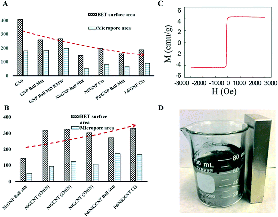
The SEM/STEM images do not provide “macroscopic” information relating to the overall surface modification resulting from ball milling and microwave irradiation treatments. To better understand the physical changes throughout the synthesis of NiGCNT and Pd/NiGCNT, physisorption experiments were conducted to measure the BET surface area and t-plot micropore area as shown in the Fig. 6(A) and (B), and in the ESI† Table S(1). Unmodified GNP material was measured to have a surface area of 402 m2 g−1. Following ball-milling, the Ni–GNP material had a surface area of 144 m2 g−1. The drastic decrease in the BET surface area of GNP is due to the restacking of graphene sheet which is undesired as catalyst supports. After microwave irradiation process to grow CNTs on GNP, the BET surface area increased from 144 m2 g−1 (Ni/GNP BM) to 319 m2 g−1 (NiGCNT 1 min) as shown in Fig. 6(B). To confirm the increase in surface area from the Ni/GCNT BM sample to NiGCNT 1 min sample was not due to thermal exfoliation of the GNP during the microwave process, a control experiment using only the GNP without Ni precursors or nanoparticles for the ball milling and microwave process was carried out. The result shows that the surface area of GNP after ball milling (GNP ball milling) is 258 m2 g−1 as shown in Fig. 6(A). However, after 2 minutes of microwave treatment, the surface area of the sample GNP BM KMW (266 m2 g−1) remained the same compared with the sample before microwave which indicates the stacked graphene is not exfoliated under this microwave irradiation condition. For the NiGCNT 1 min sample, further microwave irradiation treatment had no significant effect on the overall surface area. Therefore, the increase in surface area between Ni/GNP BM and NiGCNT 1 min is explained by 1) growth of CNTs and 2) exfoliation of graphene sheets due to the growth of CNTs. Interestingly, additional microwave time did not further increase surface area.The surface area changes in the material after deposition of Pd nanoparticles using GNP and NiGCNT was also investigated. For the GNP support (Fig. 6(A)), the deposition of Pd nanoparticle dramatically reduces the surface area from 402 m2 g−1 (GNP) to 187 m2 g−1 (Pd/GNP CO) and 158 m2 g−1 (Pd/GNP ball mill). The magnitude in the decreased surface area is similar to the Ni/GNP BM sample. The surface area reduction is believed to be caused by the restacking of graphene. In contrast, for the same Pd deposition process on the NiGCNT material did not alter the surface area, the surface areas of NiGCNT support, Pd/NiGCNT CO, and Pd/NiGCNT BM materials were 320 m2 g−1, 330 m2 g−1, and 282 m2 g−1, respectively. This important result demonstrates the 3D NiGCNT material strongly impedes the restacking of graphene sheets.
Furthermore, it was found that the NiGCNT material also possesses magnetic properties. Fig. 6(C) shows a hysteresis loop of the NiGCNT and displays a magnetic saturation of 4.43 emu g−1. Fig. 6(D) shows that the NiGCNT can be easily separated by magnets which is advantageous for catalyst recycling.
The mechanism of the growth of carbon nanotubes
The proposed mechanism to prepare the NiGCNT support and its decoration with Pd nanoparticles (Pd/NiGCNT) involves three steps based on the systematic evaluation and characterization of the materials as shown in Fig. 7.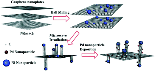 | ||
| Fig. 7 The proposed mechanism of the growth of the carbon nanotubes on graphene via a solventless microwave irradiation and its functionalization with Pd nanoparticles. | ||
The Ni precursor and the GNP were ball-milled to generate the unreduced Ni2+ nanoparticles immobilized on the graphene nanoplatelets. A solventless microwave irradiation was then introduced to reduce the Ni nanoparticles and generate the defect sites on the graphene which trapped the reduced Ni nanoparticles as anchoring sites. Graphene was then in situ consumed by the immobilized Ni nanoparticles to produce the carbon nanotubes. Two control experiments were conducted to further elucidate this growth mechanism. Ni precursor was ball-milled with activated carbon (Ni/AC) instead of GNP and treated with the same microwave irradiation settings to determine if graphene was required for the formation of CNTs. While these microwave irradiation settings generated large amounts of CNTs using Ni/GNP sample, no CNTs were generated on the Ni/AC sample (Fig. S(5)†). This suggests that neither the activated carbon nor the carbon from Ni precursor is consumed as the carbon source to generate CNT under these conditions. In the second control experiment, the Ni/GNP mixture was microwaved in a water bath which limited the local temperature on the surface of the GNP during the microwave irradiation process. The resulted material contained deposits of large Ni nanoparticles (>100 nm) on the graphene sheet as shown in ESI† Fig. S(6). However, no CNTs were fabricated suggesting that a critical temperature must be reached to overcome the energy barrier to initiate the growth process of CNTs. The solventless microwave heating is required to achieve the critical temperature to remove CO and CO2 from the graphene material which is thought to be the carbon source for CNT growth. The carbon source for growing the nanotubes is still unclear. One possible mechanism is that the deposited Ni nanoparticle directly consumes graphene as in the solid state to generate the nanotube. ESI† in Fig. S(3) shows SEM evidence of the graphene flakes etched by the Ni nanoparticles. The other suspected carbon source is from the oxygen-containing functional groups on the graphene removed as CO and CO2 during solventless microwave irradiation.
Catalytic properties
The resulting materials produced by the second ball milling method (Pd/NiGCNT BM) and by the chemical/microwave co-reduction method (Pd/NiGCNT CO) were tested for catalytic activity using a model Suzuki cross-coupling reaction shown in Table 1. The TOF were calculated based on both mole of total Pd used in the reaction and the mole of active Pd sites determined by chemisorption (ESI† S2). For comparison, a commercially available Pd on activated carbon (Pd/AC) catalyst was also tested using the same reaction conditions. The turnover frequency was used to quantify the moles of product generated in a finite time which shows the reaction rate for the same Suzuki reaction catalyzed by different catalysts. The TOF of the synthesized Pd/NiGCNT CO (115![[thin space (1/6-em)]](https://www.rsc.org/images/entities/char_2009.gif) 000 h−1) and Pd/NiGCNT BM (105
000 h−1) and Pd/NiGCNT BM (105![[thin space (1/6-em)]](https://www.rsc.org/images/entities/char_2009.gif) 000 h−1) catalysts are approximately ten times more active than commercially available Pd/AC (12
000 h−1) catalysts are approximately ten times more active than commercially available Pd/AC (12![[thin space (1/6-em)]](https://www.rsc.org/images/entities/char_2009.gif) 000 h−1). Previous publications9,11,38 suggested that high reactivity of graphene and carbon nanotube supported catalysts originated from the conducting nature of sp2 hybridized carbon. The support serves as a reservoir of electrons to facilitate the charge transfer of the supported Pd nanoparticles with the reagent in both the charge donating and charge withdrawing steps which reduce the reaction barriers of the Suzuki reactions. No conversion was observed in a reaction using the NiGCNT support only as the catalyst even when the Ni catalyst was pre-reduced and under an inert atmosphere to limit the oxidation of the Ni. Since Ni nanoparticles have been previously reported to be catalytically reactive for Suzuki reactions, a control experiment using Ni on GNP (Ni/GNP CO) fabricated using hydrazine and microwave reduction was performed. The TOF of Ni/GNP CO was measured to only be 20 h−1 for the model Suzuki reaction (Table 1). The carbon coating developed on top of the Ni nanoparticles in the NiGCNT support is assumed to be the reason for the negligible catalytic reactivity. Biphenyl byproduct of the model Suzuki reaction as shown in Table 2 was detected for Pd/NiGCNT BM and Pd/NiGCNT CO catalyzed reactions. The formation of the by-product was believed to result from the homocoupling of two equivalents of phenylboronic acid catalyzed by the Pd2+ species in the catalyst.39 This side reaction also reduced the Pd2+ to Pd0 which is the reactive species in the Suzuki reaction.
000 h−1). Previous publications9,11,38 suggested that high reactivity of graphene and carbon nanotube supported catalysts originated from the conducting nature of sp2 hybridized carbon. The support serves as a reservoir of electrons to facilitate the charge transfer of the supported Pd nanoparticles with the reagent in both the charge donating and charge withdrawing steps which reduce the reaction barriers of the Suzuki reactions. No conversion was observed in a reaction using the NiGCNT support only as the catalyst even when the Ni catalyst was pre-reduced and under an inert atmosphere to limit the oxidation of the Ni. Since Ni nanoparticles have been previously reported to be catalytically reactive for Suzuki reactions, a control experiment using Ni on GNP (Ni/GNP CO) fabricated using hydrazine and microwave reduction was performed. The TOF of Ni/GNP CO was measured to only be 20 h−1 for the model Suzuki reaction (Table 1). The carbon coating developed on top of the Ni nanoparticles in the NiGCNT support is assumed to be the reason for the negligible catalytic reactivity. Biphenyl byproduct of the model Suzuki reaction as shown in Table 2 was detected for Pd/NiGCNT BM and Pd/NiGCNT CO catalyzed reactions. The formation of the by-product was believed to result from the homocoupling of two equivalents of phenylboronic acid catalyzed by the Pd2+ species in the catalyst.39 This side reaction also reduced the Pd2+ to Pd0 which is the reactive species in the Suzuki reaction.
| Catalyst | Turn over frequency (h−1) | |||
|---|---|---|---|---|
| Suzuki reaction | C–H activation | |||
| Total Pd | Active Pd site | Total Pd | Active Pd site | |
| a Catalyst was pre-reduced by hydrazine before the reaction and conducted under Ar. | ||||
| Pd/NiGCNT CO | 115![[thin space (1/6-em)]](https://www.rsc.org/images/entities/char_2009.gif) 000 000 |
4![[thin space (1/6-em)]](https://www.rsc.org/images/entities/char_2009.gif) 653 653![[thin space (1/6-em)]](https://www.rsc.org/images/entities/char_2009.gif) 000 000 |
650 | 26![[thin space (1/6-em)]](https://www.rsc.org/images/entities/char_2009.gif) 300 300 |
| Pd/NiGCNT BM | 105![[thin space (1/6-em)]](https://www.rsc.org/images/entities/char_2009.gif) 000 000 |
1![[thin space (1/6-em)]](https://www.rsc.org/images/entities/char_2009.gif) 664 664![[thin space (1/6-em)]](https://www.rsc.org/images/entities/char_2009.gif) 400 400 |
1200 | 19![[thin space (1/6-em)]](https://www.rsc.org/images/entities/char_2009.gif) 000 000 |
| Pd/AC | 12![[thin space (1/6-em)]](https://www.rsc.org/images/entities/char_2009.gif) 000 000 |
— | 15 | — |
| Ni/GNP COa | 20 | — | 0 | — |
| NiGCNTa | 0 | — | 0 | — |
The Pd/NiGCNT catalysts were also tested using a model C–H activation reaction shown in Table 1. The Pd/NiGCNT BM catalyst was significantly more active than all other catalysts tested. Since the catalytic cycle of the C–H activation is a Pd2+ to Pd4+ cycle (Fig. S8†), the higher reactivity of Pd/NiGCNT BM catalyst is believed to originate from the higher Pd2+ content as measured by XPS.
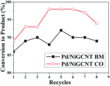
Recyclability tests using the model Suzuki reaction show that both the Pd/NiGCNT BM and Pd/NiGCNT CO catalysts can be recycled and reused for eight times without losing activity, Fig. 8. The product yield reached a maximum after several cycles since the reaction resulted in the higher amount of biphenyl byproduct in the initial 2 to 3 cycles. The Pd/NiGCNT BM catalyst generated an even higher ratio of biphenyl by-product even after several recycles which may result from the higher Pd2+ content in the Pd/NiGCNT BM catalyst. To determine the amount of Ni and Pd leached out during the reaction, a hot filtration step was added after completion of the reaction. The filtrate was then tested using ICP-OES. The leached Ni content was 1.5 ppm (about 4.8% of overall Ni in the catalyst) for Pd/NiGCNT CO and 1.4 ppm (4.7%) for Pd/NiGCNT BM in the model Suzuki reaction. The leached Pd content was 980 ppb (2.7%) for Pd/NiGCNT CO and 900 ppb (2.6%) for Pd/NiGCNT BM in the model Suzuki reaction. The leached Ni were believed to come from the Ni nanoparticles that were not decorated with carbon.
Conclusions
An innovative approach to the synthesis of a 3D catalyst support combining CNTs and graphene (NiGCNT) was developed via a ball milling to load Ni precursor onto graphene nanoplatelets and a subsequent solventless microwave irradiation steps to grow CNTs directly on the surface of graphene. Furthermore, the synthesized 3D NiGCNT material via a facile, solventless, and rapid method was found to be highly resistant to aggregation and restacking of graphene sheets. The Pd nanoparticles supported on the NiGCNT material showed extremely high reactivity for both Suzuki and C–H activation reactions with turnover frequencies about ten times higher than commercially available Pd on activated carbon catalyst for cross-coupling reaction and 100 times more active in C–H activation reaction. The multifunctional properties of the NiGCNT support were confirmed to facilitate a recycle method via magnetic separation and the catalyst was reused eight times without losing activity.Conflicts of interest
There are no conflicts to declare.Acknowledgements
This work was supported by the Center for Rational Catalyst Synthesis an Industry/University Cooperative Research Center IIP1464595, the start-up funding 291284, and Nanomaterials Core Characterization Facility at Virginia Commonwealth University.Notes and references
- J. G. de Vries and S. D. Jackson, Catal. Sci. Technol., 2012, 2, 2009 RSC.
- F. Zaera, Chem. Soc. Rev., 2013, 42, 2746–2762 RSC.
- N. Mizuno and M. Misono, Chem. Rev., 1998, 98, 199–218 CrossRef CAS PubMed.
- J. Pritchard, G. A. Filonenko, R. van Putten, E. J. M. Hensen and E. A. Pidko, Chem. Soc. Rev., 2015, 44, 3808–3833 RSC.
- A. K. Vannucci, L. Alibabaei, M. D. Losego, J. J. Concepcion, B. Kalanyan, G. N. Parsons and T. J. Meyer, Proc. Natl. Acad. Sci. U. S. A., 2013, 110, 20918–20922 CrossRef CAS PubMed.
- C. J. Kong, D. Fisher, B. K. Desai, Y. Yang, S. Ahmad, K. Belecki and B. F. Gupton, Bioorg. Med. Chem., 2017, 25, 6203–6208 CrossRef CAS PubMed.
- S. Navalon, A. Dhakshinamoorthy, M. Alvaro, M. Antonietti and H. Garcia, Chem. Soc. Rev., 2017, 46, 4501–4529 RSC.
- M. Hu, Z. Yao and X. Wang, Ind. Eng. Chem. Res., 2017, 56, 3477–3502 CrossRef CAS.
- Y. Yang, C. E. Castano, B. F. Gupton, A. C. Reber and S. N. Khanna, Nanoscale, 2016, 8, 19564–19572 RSC.
- S. E. Gilliland, J. M. M. Tengco, Y. Yang, J. R. Regalbuto, C. E. Castano and B. F. Gupton, Appl. Catal., A, 2018, 550, 168–175 CrossRef CAS.
- Y. Yang, A. C. Reber, S. E. Gilliland, C. E. Castano, B. F. Gupton and S. N. Khanna, J. Catal., 2018, 360, 20–26 CrossRef CAS.
- S. Ghobadi, S. Mehraeen, R. Bakhtiari, B. Shamloo, V. Sadhu, M. Papila, F. C. Cebeci and S. A. Gursel, RSC Adv., 2016, 6, 92434–92442 RSC.
- X. Li, Y. M. Liu, W. G. Li, C. Y. Li, J. G. Sanjayan, W. H. Duan and Z. Li, Constr. Build. Mater., 2017, 145, 402–410 CrossRef CAS.
- S.-H. Bae, K. Karthikeyan, Y.-S. Lee and I.-K. Oh, Carbon, 2013, 64, 527–536 CrossRef CAS.
- Y. Wang, J. W. Shan and G. J. Weng, J. Appl. Phys., 2015, 118, 065101 CrossRef.
- K. Xia, H. Zhan and Y. Gu, Procedia IUTAM, 2017, 21, 94–101 CrossRef.
- R. Atif and F. Inam, Beilstein J. Nanotechnol., 2016, 7, 1174–1196 CrossRef CAS PubMed.
- K. P. Prasad, Y. Chen and P. Chen, ACS Appl. Mater. Interfaces, 2014, 6, 3387–3393 CrossRef CAS PubMed.
- A. A. Maarouf, A. Kasry, B. Chandra and G. J. Martyna, Carbon, 2016, 102, 74–80 CrossRef CAS.
- A. Ansaldo, P. Bondavalli, S. Bellani, A. E. D. R. Castillo, M. Prato, V. Pellegrini, G. Pognon and F. Bonaccorso, ChemNanoMat, 2017, 3, 436–446 CrossRef CAS.
- Y. Liu, Y. Liu, S. Qin, Y. Xu, R. Zhang and F. Wang, Nano Res., 2017, 10, 1880–1887 CrossRef CAS.
- R. Brukh and S. Mitra, Chem. Phys. Lett., 2006, 424, 126–132 CrossRef CAS.
- L. Wang, J. Han, Y. Zhu, R. Zhou, C. Jaye, H. Liu, Z.-Q. Li, G. T. Taylor, D. A. Fischer, J. Appenzeller and S. S. Wong, J. Phys. Chem. C, 2015, 119, 26327–26338 CrossRef CAS.
- J. A. Isaacs, A. Tanwani, M. L. Healy and L. J. Dahlben, J. Nanopart. Res., 2010, 12, 551–562 CrossRef.
- C. Liu and H.-M. Cheng, Mater. Today, 2013, 16, 19–28 CrossRef CAS.
- F. Liu, X. Zhang, J. Cheng, J. Tu, F. Kong, W. Huang and C. Chen, Carbon, 2003, 41, 2527–2532 CrossRef CAS.
- I.-Y. Jeon, Y.-R. Shin, G.-J. Sohn, H.-J. Choi, S.-Y. Bae, J. Mahmood, S.-M. Jung, J.-M. Seo, M.-J. Kim, D. Wook Chang, L. Dai and J.-B. Baek, Proc. Natl. Acad. Sci. U. S. A., 2012, 109, 5588–5593 CrossRef CAS PubMed.
- V. Leon, M. Quintana, M. A. Herrero, J. L. G. Fierro, A. d. l. Hoz, M. Prato and E. Vazquez, Chem. Commun., 2011, 47, 10936–10938 RSC.
- X. Fan, D. W. Chang, X. Chen, J.-B. Baek and L. Dai, Curr. Opin. Chem. Eng., 2016, 11, 52–58 CrossRef.
- H. Zhu, Y. Cao, J. Zhang, W. Zhang, Y. Xu, J. Guo, W. Yang and J. Liu, J. Mater. Sci., 2016, 51, 3675–3683 CrossRef CAS.
- Z. Chen, H. Miao, J. Wu, Y. Tang, W. Yang, L. Hou, F. Yang, X. Tian, L. Zhang and Y. Li, Ind. Eng. Chem. Res., 2017, 56, 6939–6944 CrossRef CAS.
- R. Janot and D. Guérard, Carbon, 2002, 40, 2887–2896 CrossRef CAS.
- A. R. Siamaki, Y. Lin, K. Woodberry, J. W. Connell and B. F. Gupton, J. Mater. Chem. A, 2013, 1, 12909–12918 RSC.
- D. Voiry, J. Yang, J. Kupferberg, R. Fullon, C. Lee, H. Y. Jeong, H. S. Shin and M. Chhowalla, Science, 2016, 353, 1413–1416 CrossRef CAS PubMed.
- M. Darvishi and J. Seyed-Yazdi, Surf. Interfaces, 2016, 4, 1–8 CrossRef CAS.
- P. Tang, G. Hu, Y. Gao, W. Li, S. Yao, Z. Liu and D. Ma, Sci. Rep., 2014, 4, 5901 CrossRef CAS PubMed.
- A. L. Patterson, Phys. Rev., 1939, 56, 978–982 CrossRef CAS.
- Y. Yang, A. C. Reber, S. E. Gilliland, C. E. Castano, B. F. Gupton and S. N. Khanna, J. Phys. Chem. C, 2018, 122, 25396 CrossRef CAS.
- A. N. Cammidge and K. V. L. Crépy, J. Org. Chem., 2003, 68, 6832–6835 CrossRef CAS PubMed.
Footnote |
| † Electronic supplementary information (ESI) available. See DOI: 10.1039/c8re00185e |
| This journal is © The Royal Society of Chemistry 2019 |

