 Open Access Article
Electrocatalytic water oxidation over AlFe2B2†
Dallas K.
Mann‡
a,
Junyuan
Xu‡
b,
Natalia E.
Mordvinova
 c,
Vincent
Yannello
a,
Yasmine
Ziouani
b,
Noelia
González-Ballesteros
d,
Juliana P. S.
Sousa
b,
Oleg I.
Lebedev
c,
Yury V.
Kolen'ko
c,
Vincent
Yannello
a,
Yasmine
Ziouani
b,
Noelia
González-Ballesteros
d,
Juliana P. S.
Sousa
b,
Oleg I.
Lebedev
c,
Yury V.
Kolen'ko
 *b and
Michael
Shatruk
 *a
*a
aDepartment of Chemistry and Biochemistry, Florida State University, 95 Chieftan Way, Tallahassee, FL 32306, USA. E-mail: shatruk@chem.fsu.edu
bInternational Iberian Nanotechnology Laboratory, Braga 4715-330, Portugal. E-mail: yury.kolenko@inl.int
cLaboratoire CRISMAT, UMR 6508, CNRS-Ensicaen, Caen 14050, France
dInorganic Chemistry Department, Biomedical Research Centre (CINBIO), Universidade de Vigo, Vigo 36210, Spain
First published on 23rd January 2019
Abstract
We report excellent electrocatalytic performance by AlFe2B2 in the oxygen-evolution reaction (OER). The inexpensive catalytic material, prepared simply by arc-melting followed by ball-milling, exhibits high stability and sustained catalytic performance under alkaline conditions. The overpotential value of 0.24 V observed at the current density of 10 mA cm−2 remained constant for at least 10 days. Electron microscopy and electron energy loss spectroscopy performed on the initial ball-milled material and on the material activated under electrocatalytic conditions suggest that the catalytic mechanism involves partial leaching of Al from the layered structure of AlFe2B2 and the formation of Fe3O4 nanoclusters on the exposed [Fe2B2] layers. Thus, the AlFe2B2 structure serves as a robust supporting material and, more importantly, as a pre-catalyst to the in situ formed active electrocatalytic sites. Comparative electrochemical measurements demonstrate that the electrocatalytic performance of the AlFe2B2-supported Fe3O4 nanoclusters substantially exceeds the results obtained with unsupported nanoparticles of Fe3O4, FeB, or such benchmark OER catalysts as IrO2 or RuO2. The excellent catalytic performance and long-term stability of this system suggests that AlFe2B2 can serve as a promising and inexpensive OER electrocatalyst.
Introduction
Fast depletion of fossil fuels drives extensive research efforts aimed at the development of renewable energy sources.1 Solar-powered fuel cells are one of the desired clean-energy technologies, which rely on the utilization of sun and water as renewable energy sources.2 Water electrolysis can be divided into two half reactions, hydrogen evolution reaction (HER) and oxygen evolution reaction (OER). In practice, the overall voltage required for electrocatalytic water splitting is substantially larger than the minimum thermodynamic value of 1.23 V. The excess voltage, known as overpotential, is due to various kinetic factors involved in the HER and OER processes.3 The goal of electrocatalysis is to decrease the overpotential and afford more energy-efficient water splitting.The extensive several-decade body of research into the HER and OER electrocatalysts4 suggests some important criteria for the development of new catalytic systems: (1) for practical implementation, the catalyst should be heterogeneous; (2) to offer a viable alternative to fossil fuels, the catalyst should be inexpensive and composed of earth-abundant elements; (3) the catalyst should exhibit long-term chemical stability under extreme catalytic conditions; (4) the catalyst should combine active catalytic sites with a robust support for uninterrupted performance with high turnover frequency (TOF).
The state of the art electrocatalysts for HER and OER are Pt and IrO2 or RuO2, respectively.5 These catalysts are based on platinum group metals (PGMs), which are expensive and limited in their reserves. To that end, many recent works have focused on the investigation of electrocatalysts that incorporate first-row transition metals.4d,5,6 Providing a high surface area conductive support for the deposition of active catalyst nanoparticles is a widely accepted method for achieving heterogeneous catalysis and improving the long-term stability of the nanoscaled catalyst. For example, CoOx, one of the best catalysts for electrolytic water splitting, shows excellent performance in the presence of phosphate anions, which allegedly promote the formation of a supported and self-healing catalyst structure with easily accessible catalytic sites.4c
An alternative strategy for achieving a supported catalyst with high surface area uses “multicomponent” materials, in which different parts of the structure can serve as the active catalytic sites and the inert conductive support. Such architecture allows the implementation of the active site separation concept, which has been shown to be effective in a number of intermetallic catalysts. As an example of this strategy, AlMoB has been recently reported as an efficient HER electrocatalyst.7 The material showed high stability under acidic conditions. In addition, it was found that the catalytic performance improved when the material was pre-etched under basic conditions. In alkaline solution, the Al atoms sandwiched between the MoB layers are etched away to open up the catalytically active transition metal sites that subsequently catalyze HER.8 The underlying structure of AlMoB thus acts as a robust conductive support for the catalytically active sites separated by the partially etched Al layers.
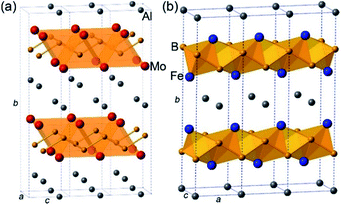
The crystal structure of AlMoB (Fig. 1a) has attracted our attention due to its similarity with the structure of another ternary intermetallic compound, AlFe2B2 (Fig. 1b), which we earlier explored as a promising magnetocaloric material.9 We have hypothesized that similar Al-etching procedure can affect the layered structure of AlFe2B2 by exposing the [Fe2B2] layers for the subsequent electrocatalytic reaction. Indeed, a theoretical analysis presented herein demonstrates that the bonding between the Al and [Fe2B2] layers in this structure is substantially weaker than the Fe–B and B–B bonds within the [Fe2B2] layer. We have also recently reported in situ formation of highly active nickel oxide nanocluster OER electrocatalysts from nickel phosphide scaffolds.10 By analogy with the binary Ni–P, we hypothesized that [Fe2B2] layers could serve as an interesting precursor for Fe-based OER electrocatalyst. This hypothesis is followed by an experimental demonstration that AlFe2B2 affords efficient OER with a low overpotential and remarkably high stability of the electrocatalyst. A comprehensive investigation of the electrocatalytic process reveals that AlFe2B2 acts as a robust scaffold for in situ formation of catalytically active Fe3O4 nanoclusters on the surface of the [Fe2B2] layers. The excellent catalytic performance and long-term stability coupled to the convenient synthesis suggest that this system can serve as a promising and inexpensive OER electrocatalyst.
Materials and methods
Synthesis
All manipulations during sample preparation were carried out in an Ar-filled dry box (content of O2 < 0.5 ppm). Powders of aluminum (99.97%), iron (98%), crystalline boron (98%), and iron boride (FeB, 98%) were obtained from Alfa Aesar. The iron powder was additionally purified by heating in a flow of H2 gas at 500 °C for 5 h. The other materials were used as received.AlFe2B2 was synthesized as previously reported.9 Starting materials were mixed in a Al![[thin space (1/6-em)]](https://www.rsc.org/images/entities/char_2009.gif) :
:![[thin space (1/6-em)]](https://www.rsc.org/images/entities/char_2009.gif) Fe
Fe![[thin space (1/6-em)]](https://www.rsc.org/images/entities/char_2009.gif) :
:![[thin space (1/6-em)]](https://www.rsc.org/images/entities/char_2009.gif) B = 3
B = 3![[thin space (1/6-em)]](https://www.rsc.org/images/entities/char_2009.gif) :
:![[thin space (1/6-em)]](https://www.rsc.org/images/entities/char_2009.gif) 2
2![[thin space (1/6-em)]](https://www.rsc.org/images/entities/char_2009.gif) :
:![[thin space (1/6-em)]](https://www.rsc.org/images/entities/char_2009.gif) 2 ratio (a total weight of 0.35 g) and pressed into a pellet, which was arc-melted in an argon-filled glovebox. The pellet was re-melted 4 times to achieve uniform melting. To maximize the sample's homogeneity, it was sealed in a silica tube under vacuum (∼10−5 Torr) and annealed at 900 °C for 1 week. The annealed sample was ground and subjected to powder X-ray diffraction (PXRD), which revealed AlFe2B2 as the major phase and Al13F4 as a minor byproduct. The latter was removed by treating the sample for 3–5 min with dilute (1
2 ratio (a total weight of 0.35 g) and pressed into a pellet, which was arc-melted in an argon-filled glovebox. The pellet was re-melted 4 times to achieve uniform melting. To maximize the sample's homogeneity, it was sealed in a silica tube under vacuum (∼10−5 Torr) and annealed at 900 °C for 1 week. The annealed sample was ground and subjected to powder X-ray diffraction (PXRD), which revealed AlFe2B2 as the major phase and Al13F4 as a minor byproduct. The latter was removed by treating the sample for 3–5 min with dilute (1![[thin space (1/6-em)]](https://www.rsc.org/images/entities/char_2009.gif) :
:![[thin space (1/6-em)]](https://www.rsc.org/images/entities/char_2009.gif) 1 v/v) aqueous solution of HCl.
1 v/v) aqueous solution of HCl.
Powder X-ray diffraction
Room-temperature PXRD was carried out on a Panalytical X'Pert Pro diffractometer with an X'Celerator detector using Cu-Kα radiation (λ = 1.54187 Å). Each pattern was recorded in the 2θ range of 10° to 80° with a step of 0.05° and the total collection time of 1 h. The analysis of PXRD patterns was carried out with the HighScore Plus software (Panalytical).11Electrocatalyst preparation
The phase-pure sample of AlFe2B2 was ball-milled at 1725 rpm for 1 h in an 8000 M High-Energy Mixer/Mill (SPEX), using a stainless-steel ball-milling set. The milling was carried out under Ar to minimize surface oxidation. The PXRD of the ball-milled sample revealed broadening of diffraction peaks, in accord with the decreased particle size. No traces of impurity phases were observed, except for a minor peak of Al2O3 (which will be dissolved under basic conditions of electrochemical testing). Specific surface areas (SBET) of the as-prepared AlFe2B2 and reference catalysts were estimated using the Brunauer–Emmett–Teller (BET) model with the Autosorb iQ2 analyzer (Quantachrome). The ball-milled sample of AlFe2B2 was converted into an electrocatalyst ink by ultrasonically dispersing 5 mg of the material in 1000 μL of ethanol containing 50 μL of a Nafion solution (Sigma-Aldrich, 5 wt%). To prepare an electrode for catalytic tests, 200 μL of the ink was loaded on a Ni foam (Heze Jiaotong, 110 pores per inch, 0.3 mm thick, cleaned by ultrasonication in 6 M HCl) with an exposed area of 1.0 cm2, leading to a loading density of ∼1.0 mg cm−2. The electrode was then allowed to dry naturally under ambient conditions.Electrochemical measurements
Electrochemical measurements were conducted at 25 °C, using a Biologic VMP-3 potentiostat/galvanostat. The OER performance of various catalysts was evaluated in a three-electrode system using 1.0 M KOH electrolyte, in which the catalytic electrode, the saturated calomel electrode (SCE), and a Pt wire served as the working, reference, and counter electrodes, respectively. Prior to each measurement, the SCE electrode was calibrated in Ar/H2-saturated 0.5 M H2SO4 solution, using a clean Pt wire as the working electrode. Unless stated otherwise, all potentials reported in this work were converted to a reversible hydrogen electrode (RHE) reference scale according to the following equation: ERHE = ESCE + 0.059pH + 0.241. An iR-correction of 85% was applied in the polarization experiments to compensate for the voltage drop between the reference and working electrodes, which was evaluated by a single-point high-frequency impedance measurement.OER anodic polarization curves were recorded with a scan rate of 5 mV s−1 in the range from 1.0 to 1.7 V vs. RHE. Impedance spectroscopy measurements were carried out at the overpotential of 0.26 V in the frequency range from 105 to 10−2 Hz with a 10 mV sinusoidal perturbation. The catalytic stability of the electrodes was evaluated as a function of time at constant current density of 10 mA cm−2.
Calculation of turnover frequencies (TOFs)
The O2 TOFs for the electrocatalysts were estimated as TOF (s−1) = (jA)/(4Fn), where j is the current density (A cm−2) at a given overpotential, A is the surface area of the electrode (1.0 cm2), F is the Faraday constant (96![[thin space (1/6-em)]](https://www.rsc.org/images/entities/char_2009.gif) 485 C mol−1), and n is the amount of metal in the electrode (mol), determined as n = 1.0 mg cm−2 × 1.0 cm2 × 10−3/metal molar mass. We assumed that all of the metal ions were catalytically active and thereby calculated their TOFs. Notably, some metal sites were indeed inaccessible during OER, and thus the calculated TOFs represent the minimum possible values.
485 C mol−1), and n is the amount of metal in the electrode (mol), determined as n = 1.0 mg cm−2 × 1.0 cm2 × 10−3/metal molar mass. We assumed that all of the metal ions were catalytically active and thereby calculated their TOFs. Notably, some metal sites were indeed inaccessible during OER, and thus the calculated TOFs represent the minimum possible values.
Transmission electron microscopy
The transmission electron microscopy (TEM), high-angle annular dark-field scanning TEM (HAADF-STEM), electron diffraction (ED), energy-dispersive X-ray spectroscopy (STEM-EDX) and electron energy loss spectroscopy (STEM-EELS) in STEM mode studies were performed using a JEM-ARM200F microscope (cold field-emission gun, probe and image aberration corrected, equipped with CENTURIO EDX detector and GIF Quantum). TEM samples were prepared by crushing a sample in an agate mortar in ethanol and depositing the obtained suspension on a Cu carbon holey grid.Quantum-chemical calculations
Density-functional band structure calculations and crystal orbital Hamilton population (COHP) analysis12 were performed using the tight binding-linear muffin tin orbitals-atomic sphere approximation (TB-LMTO-ASA) software.13 Published structural parameters of AlFe2B2 were used14 with no theoretical geometry optimization. Fe 4s, 3d, and 4p, Al 3s, 3p, and 3d, and B 2s, 2p, and 3d states were treated as valence orbitals (with Al and B 3d states downfolded). No additional empty spheres were needed to reach an overlap volume of 8.731%. A 23 × 6 × 23 k-point mesh was used to generate COHP curves for five shortest interatomic contacts.Results and discussion
Synthesis and analysis of AlFe2B2
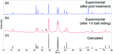
As shown by us previously, phase-pure AlFe2B2 can be synthesized by means of arc-melting followed by homogenizing annealing at 900 °C. A short treatment of the annealed sample with diluted HCl is required to eliminate the minor Al13Fe4 impurity. The as-prepared AlFe2B2 was ball-milled for 1 h to maximize the surface area of the material. The PXRD pattern of the ball-milled sample revealed that the phase composition of the material had been preserved after ball-milling, although a minor peak observed at 2θ = 37° suggests the appearance of Al2O3 byproduct. The impurity, however, was readily dissolved under the electrochemical testing conditions (pH = 14) used in this work. The PXRD analysis also revealed broadening of diffraction lines in the pattern of the ball-milled sample as compared to the bulk sample (Fig. 2). Analysis of the line broadening effect was carried out using the Scherrer equation,15 which relates the average particle size (D) to the line broadening (Δ(2θ)) at various diffraction angles (θ): D = Kλ/[Δ(2θ) × cos![[thin space (1/6-em)]](https://www.rsc.org/images/entities/char_2009.gif) θ]. The shape factor K was set to 0.9, and Si powder was used as a standard to evaluate the intrinsic line broadening of the diffractometer. This analysis led to D ≈ 25 nm, indicating the substantial decrease in the crystallite size as compared to the bulk sample, as desired for electrocatalytic studies. This estimate, however, does not account for the line broadening due to strain introduced by ball-milling. Thus, it provides only the lower bound for the particle size, as will be demonstrated below by electron microscopy.
θ]. The shape factor K was set to 0.9, and Si powder was used as a standard to evaluate the intrinsic line broadening of the diffractometer. This analysis led to D ≈ 25 nm, indicating the substantial decrease in the crystallite size as compared to the bulk sample, as desired for electrocatalytic studies. This estimate, however, does not account for the line broadening due to strain introduced by ball-milling. Thus, it provides only the lower bound for the particle size, as will be demonstrated below by electron microscopy.
In our previous work on bulk AlFe2B2, we observed that this material also dissolves in dilute HCl (although slower than the Al13Fe4 impurity). Given the much higher stability of the binary FeB under acidic conditions,16 one might assume that the reactivity of AlFe2B2 toward the acid is initiated by leaching of Al from the space between the [Fe2B2] layers. This assumption is also supported by the fact that the Al–Fe (2.622 Å) and Al–B (2.430 Å) bond lengths are substantially longer than the bonds within the [Fe2B2] layer (B–B at 1.605 Å and Fe–B at 2.048 and 2.199 Å).
To evaluate more quantitatively the strengths of the bonds in the AlFe2B2 structure, we carried out quantum-mechanical calculations to obtain the COHP curves for each of the aforementioned interatomic contacts. Integrating the –COHP curves, shown in Fig. 3, up to the Fermi energy (EF) gives –ICOHP (Table 1), an energy value which correlates with the bond strength.12 The positive values of –ICOHP represent a negative energy term, which indicates an overall stabilizing interaction, while the negative values indicate destabilizing interaction. As expected, the B–B bonds are the strongest in the structure, while the two crystallographically unique Fe–B contacts are moderately strong. The weakest interactions are observed for the Al–Fe and Al–B contacts. As will be shown below, this finding agrees not only with our chemical intuition, but also with experimental results.
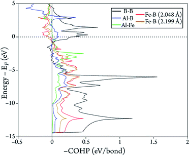 | ||
| Fig. 3 Calculated –COHP curves for the five shortest interatomic contacts in the crystal structure of AlFe2B2. | ||
| Bond | Distance (Å) | –ICOHP (eV/bond) |
|---|---|---|
| B–B | 1.605 | 5.13 |
| Al–Fe | 2.622 | 1.02 |
| Al–B | 2.430 | 1.06 |
| Fe–B | 2.048 | 2.75 |
| 2.199 | 2.15 |
Electrocatalytic studies
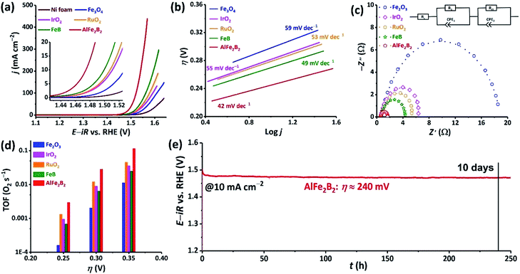
The nanoparticles of AlFe2B2 obtained by ball-milling were converted into a catalyst ink and loaded on a Ni foam current collector. This electrocatalytic assembly was evaluated in 1 M KOH electrolyte, revealing high OER activity of the AlFe2B2 electrocatalyst. Specifically, the current densities of 10, 100, and 300 mA cm−2 were achieved at remarkably low overpotentials (η) of only 240, 290, and 320 mV, respectively. For comparison, we evaluated (under the same conditions) the bare Ni foam and four other control catalysts, FeB (SBET = 43 m2 g−1), Fe3O4 (SBET = 74 m2 g−1),17 RuO2 (SBET = 11 m2 g−1), and IrO2 (SBET = 2 m2 g−1). As can be seen from Fig. 4a, when considering the activity based on the current density by electrode surface area, AlFe2B2 exhibits substantially lower overpotentials at all current densities, outperforming all the reference systems. Further comparisons of the catalytic performance normalized by SBET18 shows that AlFe2B2 demonstrates the strongest catalytic current on anodic polarization, and only IrO2 has higher activity than the AlFe2B2-based anode (Fig. S1†).The kinetic behavior of the electrocatalysts was compared by means of Tafel and Nyquist plots. The Tafel plot relates the rate of the electrochemical reaction to the overpotential by revealing the dependence of η on the logarithmic current density: η = TS![[thin space (1/6-em)]](https://www.rsc.org/images/entities/char_2009.gif) log(j/j0). The Tafel slope (TS) derived from this dependence indicates how susceptible the reaction rate is to changes in the applied voltage. The Tafel plots in Fig. 4b show that AlFe2B2 exhibits not only the lowest overpotential per geometric area but also the smallest TS value in comparison to the reference electrocatalysts. An impressive TS value of 42 mV dec−1, determined for AlFe2B2, indicates the fastest OER rate in the 1 M KOH electrolyte. The Nyquist plot, obtained from the AC impedance measurements, also demonstrates a significantly smaller charge-transfer resistance for AlFe2B2 as compared to the reference electrocatalysts (Fig. 4c).
log(j/j0). The Tafel slope (TS) derived from this dependence indicates how susceptible the reaction rate is to changes in the applied voltage. The Tafel plots in Fig. 4b show that AlFe2B2 exhibits not only the lowest overpotential per geometric area but also the smallest TS value in comparison to the reference electrocatalysts. An impressive TS value of 42 mV dec−1, determined for AlFe2B2, indicates the fastest OER rate in the 1 M KOH electrolyte. The Nyquist plot, obtained from the AC impedance measurements, also demonstrates a significantly smaller charge-transfer resistance for AlFe2B2 as compared to the reference electrocatalysts (Fig. 4c).
The O2 TOFs were examined at various overpotentials (Fig. 4d). AlFe2B2 shows a TOF value of 0.12 s−1 at the overpotential of 350 mV, at which the OER benchmarks RuO2 and IrO2 achieved substantially lower TOFs values of 0.05 s−1 and 0.04 s−1, respectively.
Lastly, we observed excellent stability of the AlFe2B2 electrocatalyst under the harsh OER conditions. More specifically, under the constant current density of 10 mA cm−2, in the 1 M KOH electrolyte solution, AlFe2B2 maintained an essentially constant overpotential of 240 mV for over a 10 day period. Overall, our electrochemical studies establish AlFe2B2 as a highly active and inexpensive OER electrocatalyst with the remarkable long-term stability.
Upon examination of the catalyst's stability plot, we also noticed an obvious decrease in the overpotential value in the very beginning of the reaction (Fig. 4e). To further explore this feature, we carried out several electrocatalytic cycles and monitored the current–potential curves, which revealed that the electrocatalyst was becoming more active, exhibiting progressively lower overpotential upon the initial cycling (Fig. 5). As can be seen from these results, the overpotential appeared to stabilize after the first 20 cycles. To obtain a better insight into the origin of such behavior, we examined both the initial and activated catalysts by means of electron microscopy.
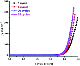 | ||
| Fig. 5 The current density vs. applied potential curves recorded over the AlFe2B2/Ni-foam electrocatalyst after OER catalytic cycles in a 1 M KOH electrolyte solution. | ||
Electron microscopy
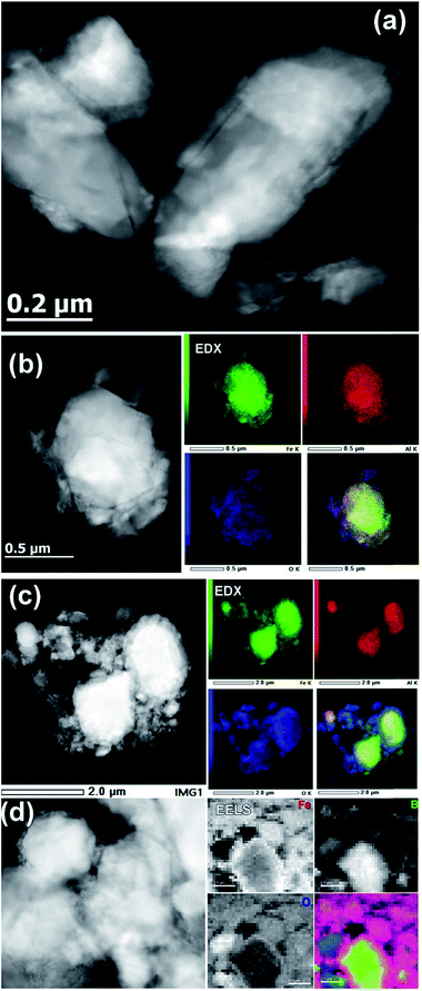
The TEM investigation showed that the original ball-milled sample contained particles of different sizes, ranging from ∼30 nm to ∼500 nm (Fig. 6a). The EDX spectroscopy showed the Al![[thin space (1/6-em)]](https://www.rsc.org/images/entities/char_2009.gif) :
:![[thin space (1/6-em)]](https://www.rsc.org/images/entities/char_2009.gif) Fe ratio of approximately 1
Fe ratio of approximately 1![[thin space (1/6-em)]](https://www.rsc.org/images/entities/char_2009.gif) :
:![[thin space (1/6-em)]](https://www.rsc.org/images/entities/char_2009.gif) 2, in agreement with the composition of the bulk material. The elemental mapping also showed the presence of a thin oxide layer (Fig. 6b), which agrees with the minor oxidation and the presence of a peak that belongs to Al2O3 in the PXRD pattern of the ball-milled material (Fig. 2b).
2, in agreement with the composition of the bulk material. The elemental mapping also showed the presence of a thin oxide layer (Fig. 6b), which agrees with the minor oxidation and the presence of a peak that belongs to Al2O3 in the PXRD pattern of the ball-milled material (Fig. 2b).
The activated sample, obtained after 20 initial OER cycles, appeared much more heterogeneous, which made its analysis difficult. Nevertheless, the overall appearance of this sample clearly revealed the formation of a core–shell structure. In comparison to the sample before the catalysis (Fig. 6b), the EDX elemental mapping showed the presence of a thick layer of iron oxide on the surface of the catalytically activated AlFe2B2 particles (Fig. 6c). The EDX elemental mapping also showed that the Al![[thin space (1/6-em)]](https://www.rsc.org/images/entities/char_2009.gif) :
:![[thin space (1/6-em)]](https://www.rsc.org/images/entities/char_2009.gif) Fe ratio had drastically decreased, from 1
Fe ratio had drastically decreased, from 1![[thin space (1/6-em)]](https://www.rsc.org/images/entities/char_2009.gif) :
:![[thin space (1/6-em)]](https://www.rsc.org/images/entities/char_2009.gif) 2 in the initial catalyst to 1
2 in the initial catalyst to 1![[thin space (1/6-em)]](https://www.rsc.org/images/entities/char_2009.gif) :
:![[thin space (1/6-em)]](https://www.rsc.org/images/entities/char_2009.gif) 6 in the activated one. This finding suggests that Al is partially leached out of the layered AlFe2B2 structure under the harsh basic conditions of electrocatalysis, a hypothesis supported by our theoretical analysis of the relative bond strengths (Table 1).
6 in the activated one. This finding suggests that Al is partially leached out of the layered AlFe2B2 structure under the harsh basic conditions of electrocatalysis, a hypothesis supported by our theoretical analysis of the relative bond strengths (Table 1).
EELS was used to probe the changes in the nature of the Fe sites during OER and to confirm the presence and localization of boron, which is difficult to detect by EDX spectroscopy. Importantly, we observed that B was consistently present in the core–shell structures (Fig. 6d), along with Fe. Recording the combined EELS elemental map required the choice of a specific energy window to monitor the presence of different elements. Nevertheless, the EELS mapping observed in Fig. 6d clearly shows the appearance of the AlFe2B2 nanoparticles (seen as the light yellow-green colored area) shelled with a layer of iron oxide (seen as a pink shell due to the combination of red (Fe) and blue (O) colors). Furthermore, a careful look at the figure also allows us to distinguish yellow-greenish areas hidden underneath the pink areas, in agreement with the in situ formation of the iron oxide layer around the AlFe2B2 particles.
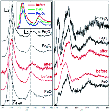
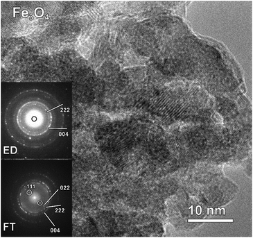
Taking into account the EDX results and combining them with the EELS data, we can conclude that these particles, indeed, consist of the AlFe2B2 core shelled with a layer of iron oxide. Analysis of the EELS data indicates that prior to catalytic testing the AlFe2B2 particles mainly contain Fe0 sites, with minor Fe3+ impurities. After activation, the thick oxide shell appears to be magnetite, Fe3O4. This phase can be distinguished from α-Fe2O3 and FeO by examining the iron L-edge and oxygen K-edge EELS fine structure observed in the energy regions around 705–725 eV and 530–570 eV, respectively (Fig. 7). In particular, the Fe L3 peak is shifted to lower energies as compared to the peak of α-Fe2O3, while the Fe L2 peak is shifted to higher energies as compared to the peak of FeO. The formation of Fe3O4 nanoparticles was also confirmed by selected area ED patterns and HRTEM imaging (Fig. 8). The ED patterns were perfectly indexed using the unit cell parameters of Fe3O4, while the Fourier transform (FT) of the HRTEM image produced an identical ring diffraction pattern with the pronounced (111) spots characteristic of Fe3O4.
We should also point out that examination of the EDX spectra did not reveal any visible traces of Ni (Fig. S2†), which excludes the possibility that the high catalytic activity of our sample could be due to the formation of mixed Ni–Fe oxyhydroxides, known to be excellent OER electrocatalysts.19
Based on these results, we propose that the excellent OER performance by AlFe2B2 is due to the partial etching of Al from the structure, followed by the surface oxidation of the exposed [Fe2B2] layers, as reflected by the following idealized reaction sequence:
| 2AlFe2B2 + 2KOH + 6H2O = 2K[Al(OH)4] + 4“FeB” + 3H2, |
| 12“FeB” + 6KOH + 17O2 = 3K2B4O7 + 4Fe3O4 + 3H2O, |
We would like to emphasize that the scheme shown above provides a much simplified version of the surface reconstruction process, which likely involves (a) the dissolution of the Al layers; (b) the formation of hydroxidic Fe species due to the oxidation of the [Fe2B2] layers under alkaline conditions; (c) the diffusion of oxygen through the shell of oxidized Fe species, leading to gradual thickening of the shell and conversion of its bulk to Fe3O4. The formation of this mixed-valent oxide shell is somewhat surprising, given the strong oxidizing conditions of the OER. Perhaps, leaching of Al contributes to the formation of Fe3O4 instead of Fe2O3. The lack of a sizable amount of FeO, Fe2O3, or FeOOH in our sample was conclusively confirmed by the EELS experiments on the Fe-L2,3 and O-K edges. Nevertheless, we believe that the very surface of the shell is covered by dynamically exchanging hydroxyl and peroxide groups, according to the proposed OER mechanisms.20
These considerations notwithstanding, our studies conclusively show that AlFe2B2 acts as a pre-catalyst, with the [Fe2B2] layers providing a robust support for the in situ generated Fe3O4 nanoclusters, which act as active sites for the OER catalysis (Fig. 9). A comparison with other non-oxide OER catalysts (borides and phosphides)10a,18 reveals a remarkably stable and efficient performance of the catalytic system developed in this work (Fig. 10).
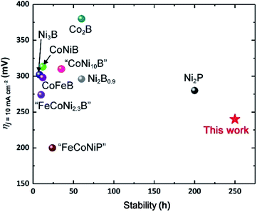 | ||
| Fig. 10 Comparison of OER electrocatalytic activity and stability of previously reported boride- and phosphide-based systems10a,21 to the performance of the AlFe2B2-based electrocatalytic system. | ||
Conclusions
In summary, we have established that the layered-structure boride, AlFe2B2, serves as an excellent OER pre-catalyst, maintaining high electrocatalytic activity for more than 10 days under alkaline conditions. This material, composed of inexpensive and earth-abundant elements, outperforms the well-known PGM-based catalysts, IrO2 and RuO2. The high OER activity of AlFe2B2 is explained by its ability to act as a robust support for in situ formed Fe3O4 nanoclusters, which serve as active catalytic sites. This notion is supported by the much poorer performance of the catalyst prepared solely with Fe3O4 nanoparticles, as well as by electron microscopy studies, which clearly demonstrate the fast formation of the Fe3O4 shell on the surface of the AlFe2B2 particles upon initial electrocatalytic cycling.It is also possible that the Al layers not only separate the [Fe2B2] layers and thus provide a more structured pre-catalyst, but also act as efficient electron-transport pathways, thus additionally facilitating the electrocatalytic reaction. To address this possibility, as well as other intriguing questions raised by the present work, we are currently expanding our studies to the other AlM2B2 (M = Cr, Mn) compounds, which are isostructural to AlFe2B2. Our findings in this direction will be reported in due course.
Author Contribution
The manuscript was written through contributions of all authors. All authors have given approval to the final version of the manuscript.Conflicts of interest
There are no conflicts to declare.Abbreviations
| BET | Brunauer–Emmett–Teller |
| COHP | Crystal orbital Hamilton population |
| ED | Electron diffraction |
| EDX | Energy dispersive X-ray |
| EELS | Electron energy loss spectroscopy |
| FT | Fourier transform |
| HAADF-STEM | High-angle annular dark-field scanning transmission electron microscopy |
| HER | Hydrogen evolution reaction |
| HRTEM | High-resolution transmission electron microscopy |
| OER | Oxygen evolution reaction |
| PGM | Platinum group metal |
| PXRD | Powder X-ray diffraction |
| RHE | Reversible hydrogen electrode |
| SCE | Saturated calomel electrode |
| TEM | Transmission electron microscopy |
| TOFs | Turnover frequencies |
Acknowledgements
The work performed at Florida State University was supported by the Petroleum Research Fund of the American Chemical Society (award 59251-ND10) and in part by the U.S. National Science Foundation (award DMR-1507233). The work performed at the International Iberian Nanotechnology Laboratory was partially supported by the European Union's Horizon 2020 research and innovation program through the CritCat Project under Grant Agreement No. 686053, and by FROnTHERA (NORTE-01-0145-FEDER-000023) project cofinanced by European Union Funds, through Portuguese NORTE 2020 program. The EELS studies were performed with the financial support from the Agence Nationale de la Recherche in the framework of the “Investissements d'avenir” program with the reference ANR-11-EQPX-0020.References
- N. S. Lewis and D. G. Nocera, Powering the planet: Chemical challenges in solar energy utilization, Proc. Natl. Acad. Sci. U. S. A., 2006, 103, 15729–15735 CrossRef CAS PubMed.
- J. R. McKone, N. S. Lewis and H. B. Gray, Will solar-driven water-splitting devices see the light of day?, Chem. Mater., 2014, 26, 407–414 CrossRef CAS.
- I. Roger, M. A. Shipman and M. D. Symes, Earth-abundant catalysts for electrochemical and photoelectrochemical water splitting, Nat. Rev. Chem., 2017, 1, 0003 CrossRef.
- (a) A. Singh and L. Spiccia, Water oxidation catalysts based on abundant 1st row transition metals, Coord. Chem. Rev., 2013, 257, 2607–2622 CrossRef CAS; (b) J. M. Saveant, Molecular catalysis of electrochemical reactions. Mechanistic aspects, Chem. Rev., 2008, 108, 2348–2378 CrossRef CAS PubMed; (c) D. A. Lutterman, Y. Surendranath and D. G. Nocera, A self-healing oxygen-evolving catalyst, J. Am. Chem. Soc., 2009, 131, 3838–3839 CrossRef CAS PubMed; (d) J. R. Galán-Mascarós, Water oxidation at electrodes modified with earth-abundant transition-metal catalysts, ChemElectroChem, 2015, 2, 37–50 CrossRef; (e) M. S. Burke, L. J. Enman, A. S. Batchellor, S. H. Zou and S. W. Boettcher, Oxygen evolution reaction electrocatalysis on transition metal oxides and (oxy)hydroxides: activity trends and design principles, Chem. Mater., 2015, 27, 7549–7558 CrossRef CAS; (f) S. Jin, Are metal chalcogenides, nitrides, and phosphides oxygen evolution catalysts or bifunctional catalysts?, ACS Energy Lett., 2017, 2, 1937–1938 CrossRef.
- C. C. L. McCrory, S. Jung, I. M. Ferrer, S. M. Chatman, J. C. Peters and T. F. Jaramillo, Benchmarking hydrogen evolving reaction and oxygen evolving reaction electrocatalysts for solar water splitting devices, J. Am. Chem. Soc., 2015, 137, 4347–4357 CrossRef CAS PubMed.
- J. Hwang, R. R. Rao, L. Giordano, Y. Katayama, Y. Yu and Y. Shao-Horn, Perovskites in catalysis and electrocatalysis, Science, 2017, 358, 751–756 CrossRef CAS PubMed.
- L. T. Alameda, C. F. Holder, J. L. Fenton and R. E. Schaak, Partial etching of Al from MoAIB single crystals to expose catalytically active basal planes for the hydrogen evolution reaction, Chem. Mater., 2017, 29, 8953–8957 CrossRef CAS.
- L. T. Alameda, P. Moradifar, Z. P. Metzger, N. Alem and R. E. Schaak, Topochemical deintercalation of Al from MoAlB: stepwise etching pathway, layered intergrowth structures, and two-dimensional MBene, J. Am. Chem. Soc., 2018, 140, 8833–8840 CrossRef CAS PubMed.
- X. Tan, P. Chai, C. M. Thompson and M. Shatruk, Magnetocaloric effect in AlFe2B2: toward magnetic refrigerants from earth-abundant elements, J. Am. Chem. Soc., 2013, 135, 9553–9557 CrossRef CAS PubMed.
- (a) J. Xu, X.-K. Wei, J. D. Costa, J. L. Lado, B. Owens-Baird, L. P. L. Goncalves, S. P. S. Fernandes, M. Heggen, D. Y. Petrovykh, R. E. Dunin-Borkowski, K. Kovnir and Y. V. Kolen'ko, Interface engineering in nanostructured nickel phosphide catalyst for efficient and stable water oxidation, ACS Catal., 2017, 7, 5450–5455 CrossRef CAS; (b) J. Y. Xu, J. P. S. Sousa, N. E. Mordvinova, J. D. Costa, D. Y. Petrovykh, K. Kovnir, O. I. Lebedev and Y. V. Kolen'ko, Al-induced in situ formation of highly active nanostructured water-oxidation electrocatalyst based on Ni-phosphide, ACS Catal., 2018, 8, 2595–2600 CrossRef CAS.
- X'Pert HighScore Plus software v. 2.2b, PANalytical B.V., Almelo, Netherlands, 2006 Search PubMed.
- R. Dronskowski and P. E. Blochl, Crystal Orbital Hamilton Populations (COHP) - energy-resolved visualization of chemical bonding in solids based on density-functional calculations, J. Phys. Chem., 1993, 97, 8617–8624 CrossRef CAS.
- R. Tank, O. Jepsen, A. Burkhardt and O. K. Andersen, The program TB-LMTO-ASA. Version 4.7, Max-Planck-Institut fur Festkorperforschung, Stuttgart, 1999 Search PubMed.
- W. Jeitschko, Crystal structure of Fe2AlB2, Acta Crystallogr., Sect. B: Struct. Crystallogr. Cryst. Chem., 1969, 25, 163–165 CrossRef CAS.
- A. L. Patterson, The Scherrer formula for X-ray particle-size determination, Phys. Rev., 1939, 56, 978–982 CrossRef CAS.
- P. Chai, S. A. Stoian, X. Y. Tan, P. A. Dube and M. Shatruk, J. Solid State Chem., 2015, 224, 52–61 CrossRef CAS.
- Y. V. Kolen'ko, M. Bañobre-López, C. Rodríguez-Abreu, E. Carbó-Argibay, A. Sailsman, Y. Piñeiro-Redondo, M. F. Cerqueira, D. Y. Petrovykh, K. Kovnir, O. I. Lebedev and J. Rivas, Large-scale synthesis of colloidal Fe3O4 nanoparticles exhibiting high heating efficiency in magnetic hyperthermia, J. Phys. Chem. C, 2014, 118, 8691–8701 CrossRef.
- S. Sun, H. Li and Z. J. Xu, Impact of surface area in evaluation of catalyst activity, Joule, 2018, 2, 1024–1027 CrossRef.
- L. Trotochaud, S. L. Young, J. K. Ranney and S. W. Boettcher, Nickel–iron oxyhydroxide oxygen-evolution electrocatalysts: the role of intentional and incidental iron incorporation, J. Am. Chem. Soc., 2014, 136, 6744–6753 CrossRef CAS PubMed.
- R. L. Doyle and M. E. G. Lyons, Kinetics and mechanistic aspects of the oxygen evolution reaction at hydrous iron oxide films in base, J. Electrochem. Soc., 2013, 160, H142–H154 CrossRef CAS.
- (a) J. Masa, P. Weide, D. Peeters, I. Sinev, W. Xia, Z. Sun, C. Somsen, M. Muhler and W. Schuhmann, Amorphous cobalt boride (Co2B) as a highly efficient nonprecious catalyst for electrochemical water splitting: oxygen and hydrogen evolution, Adv. Energy Mater., 2016, 6 Search PubMed; (b) J. Jiang, M. Wang, W. Yan, X. Liu, J. Liu, J. Yang and L. Sun, Highly active and durable electrocatalytic water oxidation by a NiB0.45/NiOx core-shell heterostructured nanoparticulate film, Nano Energy, 2017, 38, 175–184 CrossRef CAS; (c) W.-J. Jiang, S. Niu, T. Tang, Q.-H. Zhang, X.-Z. Liu, Y. Zhang, Y.-Y. Chen, J.-H. Li, L. Gu, L.-J. Wan and J.-S. Hu, Crystallinity-modulated electrocatalytic activity of a nickel(II) borate thin layer on Ni3B for efficient water oxidation, Angew. Chem., Int. Ed., 2017, 56, 6572–6577 CrossRef CAS PubMed; (d) J. M. V. Nsanzimana, Y. Peng, Y. Y. Xu, L. Thia, C. Wang, B. Y. Xia and X. Wang, An efficient and earth-abundant oxygen-evolving electrocatalyst based on amorphous metal borides, Adv. Energy Mater., 2017, 8, 1701475 CrossRef; (e) H. Chen, S. Ouyang, M. Zhao, Y. Li and J. Ye, Synergistic activity of Co and Fe in amorphous Cox–Fe–B catalyst for efficient oxygen evolution reaction, ACS Appl. Mater. Interfaces, 2017, 9, 40333–40343 CrossRef CAS PubMed; (f) N. Xu, G. Cao, Z. Chen, Q. Kang, H. Dai and P. Wang, Cobalt nickel boride as an active electrocatalyst for water splitting, J. Mater. Chem. A, 2017, 5, 12379–12384 RSC; (g) J. Zhang, X. Li, Y. Liu, Z. Zeng, X. Cheng, Y. Wang, W. Tu and M. Pan, Bi-metallic boride electrocatalysts with enhanced activity for the oxygen evolution reaction, Nanoscale, 2018, 10, 11997–12002 RSC; (h) J. Xu, J. Li, D. Xiong, B. Zhang, Y. Liu, K.-H. Wu, I. Amorim, W. Li and L. Liu, Trends in activity for the oxygen evolution reaction on transition metal (M = Fe, Co, Ni) phosphide pre-catalysts, Chem. Sci., 2018, 9, 3470–3476 RSC.
Footnotes |
| † Electronic supplementary information (ESI) available. See DOI: 10.1039/c8sc04106g |
| ‡ Both authors contributed equally to this manuscript. |
| This journal is © The Royal Society of Chemistry 2019 |

