DOI:
10.1039/C8SM01664J
(Paper)
Soft Matter, 2019,
15, 127-148
Nonlinear bending deformation of soft electrets and prospects for engineering flexoelectricity and transverse (d31) piezoelectricity†
Received
13th August 2018
, Accepted 29th November 2018
First published on 3rd December 2018
Abstract
Soft materials that exhibit electromechanical coupling are an important element in the development of soft robotics, flexible and stretchable electronics, energy harvesters, sensor and actuators. Truly soft natural piezoelectrics essentially do not exist and typical dielectric elastomers, predicated on electrostriction and the Maxwell stress effect, exhibit only a one-way electromechanical coupling. Extensive research however has shown that soft electrets i.e. materials with embedded immobile charges and dipoles, can be artificially engineered to exhibit a rather large piezoelectric-like effect. Unfortunately, this piezoelectric effect—large as it may be—is primarily restricted to an electromechanical coupling in the longitudinal direction or what is referred colloquially as the d33 piezoelectric coefficient. In sharp contrast, the transverse piezoelectric property (the so-called d31 coefficient) is rather small. This distinction has profound implications since these soft electrets exhibit negligible electromechanical coupling under bending deformation. As a result, the typically engineered soft electrets are rendered substantively ill-suited for energy harvesting as well as actuation/sensing of flexure motion that plays a critical role in applications like soft robotics. In this work, we analyze nonlinear bending deformation of a soft electret structure and examine the precise conditions that may lead to a strong emergent piezoelectric response under bending. Furthermore, we show that non-uniformly distributed dipoles and charges in the soft electrets lead to an apparent electromechanical response that may be ambiguously and interchangeably interpreted as either transverse piezoelectricity or flexoelectricity. We suggest pragmatic routes to engineer a large transverse piezoelectric (d31) and flexoelectric coefficient in soft electrets. Finally, we show that in an appropriately designed soft electret, even a uniform external electric field can induce curvature in the structure thus enabling its application as a bending actuator.
1 Introduction
One of the “holy grails” of soft multifunctional materials is to design a material that is simultaneously capable of (i) large deformation under the application of a moderate electric field,‡ (ii) generating appreciable electric field under the application of moderate forces, and (iii) (specifically) exhibit the features embodied in (i)–(ii) for bending deformation. Such soft materials with a pronounced electromechanical coupling enable applications that range from sensors,1 actuators,2 artificial muscles,3 self-powered biomedical devices,4 soft robotics5 to energy harvesting.6–8 The reader is referred to the following reviews and references therein for an overview.2,5,6,9–13
The simplicity of the aforementioned requirements is somewhat deceptive. Piezoelectric materials deform when subjected to electrical stimuli and vice versa, but the hard crystalline ones such as lead zirconium titanate (PZT), that exhibit a strong electromechanical coupling, are not capable of large deformations. Piezoelectric polymers like polyvinylidene fluoride (PVDF) do not exhibit strong electromechanical coupling (when compared to the crystalline piezoelectrics) and, with an elastic modulus in the range of 1 GPa, are not really that soft.14 Dielectric elastomers are an alternative to piezoelectrics. They are capable of large deformation but require imposition of rather high voltage. In a remarkable work, Keplinger et al.15 demonstrated an areal increase of nearly 1700% for an acrylic membrane. However, dielectric elastomers operate via the mechanism of Maxwell stress and/or electrostriction.§ In dielectric elastomers, due to the Maxwell stress effect or electrostriction, an electric field exerts a force proportional to E2 where E is the applied electric field. This force is somewhat small unless an appropriately large voltage difference is imposed. Even then, only soft dielectrics such as elastomers (with an elastic modulus of 1 MPa or less) deform appreciably for practically feasible applied electric fields. Most importantly, electrostriction is a one-way coupling i.e. an electric field will produce deformation but a mechanical stress will not induce any electricity—unlike in piezoelectric materials. Due the absence of this converse effect, energy harvesting is not easily possible unless creative design augmentations are made.¶ Additionally, the quadratic dependence of the deformation on electric fields implies that upon reversal of the applied voltage, the deformation will not reverse.
Another alternative are soft electrets. Therein, (typically) polymer foams are impregnated with immobile charges and dipoles.21–23 Both experimental and theoretical work has shown that electrets exhibit a rather large apparent piezoelectricity. Remarkably, an apparent (longitudinal) piezoelectric coefficient|| as high as 1200 pC/N – six times that of PZT – has been measured in polypropylene foams.24 Charge stability is a concern in electrets and their application is restricted to room temperature where the trapped charges tend to stabilize for sufficiently long times to enable engineering applications.
Bending deformation, in the context of piezoelectrics, dielectric elastomers and electrets, must be specifically highlighted which represents a unique challenge. Conversion of a mechanical motion into electricity (i.e. energy harvesting) is a key application area for multifunctional soft materials and is most facile under bending-type deformation as opposed to simple compression or stretching. Further, a variety of sensing and actuation contexts, including soft robotics, require flexure motion.** Bending deformation yields lower resonance frequencies and larger attainable strain which is especially advantageous for small size generators with limited environmental mechanical forces.30,31
The preceding paragraph underscores the importance of bending deformation, however, the following issues are notable:
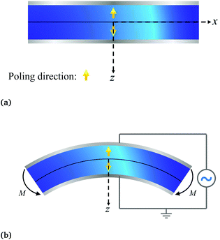
(1) Naive bending of a typical piezoelectric material will generate negligible electricity. The reason is simple. Assuming the neutral axis to be centered in the cross-section of the structural element, the polarization above the neutral line due to tension is expected to substantively cancel the polarization below the neutral axis due to compressive strains. Accordingly, bending piezoelectric devices are nearly always bimorphs. We remark that the bending piezoelectric device is based on the d31 piezoelectric effect (or transverse piezoelectricity) which is defined as the linear coupling between deformation in axial direction and electric field in thickness direction. The working principle of bending piezoelectric actuator is shown in Fig. 1 where two layers of piezoelectric film with oppositely poled directions are attached to each other. An externally applied electric field creates a positive strain in one of the films and a negative one in the other; resulting therefore in the flexure of the entire structure.
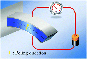 |
| | Fig. 1 Bending piezoelectric actuator is based on the so-called d31 piezoelectric effect. Typically, this actuator is made of two layers of piezoelectric materials with opposite poling directions. Generation of displacement in opposite directions in response to applied electric field bends the structure. | |
(2) Special arrangements are also required to ensure bending actuation of dielectric elastomers under an electric field. The application of an electric field on a dielectric elastomer thin film structure will simply compress the film in its thickness direction. As an example of an approach to induce flexure, He and coworkers32 used pre-stretched films. Of course, as already indicated earlier, since the Maxwell stress effect/electrostriction are a one-way electromechanical coupling, sensing and energy harvesting is not easily possible.
(3) Since electrets exhibit an apparent piezoelectricity—and a rather large one at that—they would appear to be a viable solution. Unfortunately, this is not the case. As well-articulated by the experimental papers,23,33 the emergent piezoelectricity of electrets is largely restricted to the longitudinal direction i.e. a large d33 piezoelectric coefficient but a very small value for d31 piezoelectric coefficient is reported. This shortcoming ensures that bending/harvesting is not easily possible.††
(4) It is germane here to allude to another type of electromechanical coupling mechanism that has generated much attention in recent years—flexoelectricity. In this phenomenon, a strain gradient generates electrical polarization.‡‡ Various experiments have confirmed the existence of flexoelectricity in different materials including soft polymers,35,36 hard crystalline ceramics37,38 and biological membranes.39,40 Furthermore, several review articles have recently summarized theoretical and experimental activities in this topic.41–46 In addition, several numerical studies have been preformed to analyze flexoelectric behavior of materials. Thai et al.47 presented an approach to construct a numerical framework which can account for both flexoelectricity and the Maxwell stress effects in finite deformation and also can treat material interfaces effectively. Ghasemi et al.48 presented a topology optimization of flexoelectric composites to enhance electromechanical performance. Since bending is in fact the most suitable form of strain gradient that can elicit a flexoelectric response, flexoelectricity could be considered as a reliable mechanism for bending based electro-mechanical devices. However, the effect is rather weak, and very large strain gradients (or extreme bending curvatures) are required for the flexoelectric effect to be significant. Only at nano-scale feature size is this effect considerable where a large strain gradient is easily achievable. However, we note that in the converse flexoelectric effect, an electric field gradient is required to create curvature and uniform electric field will not bend the material.44
With the preceding paragraphs as the appropriate context, the following questions motivate the current work:
(1) What are the theoretical underpinnings for the small value of transverse piezoelectricity (d31 coefficient) in typical electret foams?
(2) Based on a suitable theoretical model, what are the physical and quantitative insights to engineer a large transverse piezoelectric coefficient in electrets?
(3) Is it possible to create an electret structure that will directly couple curvature to uniformly imposed electric fields and vice versa? This is not possible in piezoelectrics and dielectric elastomers
(4) As well-established, embedding charges and dipoles in soft materials lead to an emergent piezoelectric response. Directly relevant to the preceding question, can embedding charges and dipoles lead to an emergent flexoelectricity as well?
To answer the afore-posed questions, in this paper, we rigorously analyze the nonlinear deformation of soft electrets under in-plane deformation. We provide insights into the reasons underlying the marginal d31 effect in conventional soft electrets under an in-plane stretch. Using the developed theoretical framework, we propose design guidelines to create a substantial emergent d31 in electrets such that electrical energy is harvested from flexure (Fig. 2a). Specifically we determine the emergent piezoelectric and flexoelectric coefficients. Intriguingly, we also are able to demonstrate that with appropriate design of charge and dipole placements in electrets, bending can be directly induced with the application of a uniform electric field—(Fig. 2b and c).
 |
| | Fig. 2 (a) Electrical energy may be harvested from bending deformation of a material with suitable form of electromechanical coupling. (b) The flexure actuator functionality of an electromechanical material which bends upon the application of an electric field—this is not easily feasible even in piezoelectric unless design augmentations are made by using bimorphs, pre-stretch among other approaches. (c) The change in direction of deformation due a reversal of electric field. | |
The paper is organized as follows. In Section 2, a general theoretical framework for nonlinear electrostatics of deformable media is summarized in a form suitable for the present work. In Section 3, we present an analysis of conventional soft electrets under in-plane deformation to understand the experiments showing a small d31 effect. Bending behavior of soft dielectrics is presented in Section 4 and several physically meaningful design scenarios are discussed in Section 5.
2 General theoretical framework
There are numerous, essentially equivalent, ways that electrostatics of deformable continua may be formulated.16,17,49–57 In this work, we have favored the exposition by Liu58 who has also compared the various formulations that exist in the literature.
Let ΩR be a continuum deformable body in the reference configuration. This body is located in an ambient medium such that body and ambient medium occupy domain VR. Thermodynamic state of the body is described by deformation χ: ΩR → ![[Doublestruck R]](https://www.rsc.org/images/entities/char_e175.gif) 3 (which maps material points X from the reference configuration to the spatial points x in the current configuration Ω) and polarization
3 (which maps material points X from the reference configuration to the spatial points x in the current configuration Ω) and polarization ![[P with combining tilde]](https://www.rsc.org/images/entities/b_char_0050_0303.gif) : ΩR →
: ΩR → ![[Doublestruck R]](https://www.rsc.org/images/entities/char_e175.gif) 3. Deformation and polarization outside of the body are zero. Moreover, the gradient, divergence and curl operators in the current configuration are denoted by “grad”, “div” and “curl”, respectively. Gradient in the reference configuration is denoted by “∇”. The deformation gradient tensor is defined as F = ∇χ and the Jacobian is J = det
3. Deformation and polarization outside of the body are zero. Moreover, the gradient, divergence and curl operators in the current configuration are denoted by “grad”, “div” and “curl”, respectively. Gradient in the reference configuration is denoted by “∇”. The deformation gradient tensor is defined as F = ∇χ and the Jacobian is J = det![[thin space (1/6-em)]](https://www.rsc.org/images/entities/char_2009.gif) F.
F.
Maxwell's equations in the current configuration take the following familiar form:
| | curl![[thin space (1/6-em)]](https://www.rsc.org/images/entities/char_2009.gif) e = 0, div e = 0, div![[thin space (1/6-em)]](https://www.rsc.org/images/entities/char_2009.gif) d = ρe, d = ε0e + p in V, d = ρe, d = ε0e + p in V, | (1) |
where
e,
d,
p and
ρe are the true electric field, the electric displacement, the polarization, and the external charge density in the current configuration, respectively. Also,
ε0 denotes the electric permittivity of the ambient medium. From the first of
eqn (1), we can define a scalar electric potential
ξ:
ΩR →
![[Doublestruck R]](https://www.rsc.org/images/entities/char_e175.gif)
, such that
e = −grad
![[thin space (1/6-em)]](https://www.rsc.org/images/entities/char_2009.gif) ξ
ξ. Composition map can be used to denote
e,
d and
p in the reference configuration
| | | E = e∘χ D = d∘χ P = p∘χ. | (2) |
In addition we define the nominal electric displacement
![[D with combining tilde]](https://www.rsc.org/images/entities/b_char_0044_0303.gif)
, the nominal electric field
Ẽ and the nominal polarization
![[P with combining tilde]](https://www.rsc.org/images/entities/b_char_0050_0303.gif)
as
| | Ẽ = FTE, ![[D with combining tilde]](https://www.rsc.org/images/entities/b_char_0044_0303.gif) = JF−1D, = JF−1D, ![[P with combining tilde]](https://www.rsc.org/images/entities/b_char_0050_0303.gif) = JP. = JP. | (3) |
Maxwell's equations in the reference configuration can then be derived to be:
| | ∇·![[D with combining tilde]](https://www.rsc.org/images/entities/b_char_0044_0303.gif) = = ![[small rho, Greek, tilde]](https://www.rsc.org/images/entities/i_char_e0e4.gif) e, e, ![[D with combining tilde]](https://www.rsc.org/images/entities/b_char_0044_0303.gif) = −ε0JC−1∇ξ + F−1 = −ε0JC−1∇ξ + F−1![[P with combining tilde]](https://www.rsc.org/images/entities/b_char_0050_0303.gif) in VR, in VR, | (4) |
where
![[small rho, Greek, tilde]](https://www.rsc.org/images/entities/i_char_e0e4.gif) e
e =
Jρe∘
χ for volume electric charge density and for surface charge density,
J should be replaced with the surface Jacobian.
The total free energy of the system is written as§§
| |  | (5) |
where
ψ:
![[Doublestruck R]](https://www.rsc.org/images/entities/char_e175.gif) 3
3 ×
![[Doublestruck R]](https://www.rsc.org/images/entities/char_e175.gif) 3×3
3×3 ×
![[Doublestruck R]](https://www.rsc.org/images/entities/char_e175.gif) 3
3 →
![[Doublestruck R]](https://www.rsc.org/images/entities/char_e175.gif)
is the internal energy function of the body
ΩR and
nR is the unit normal to the boundary ∂
VR. Also,
ξb:
ΓD →
![[Doublestruck R]](https://www.rsc.org/images/entities/char_e175.gif)
and
![[t with combining tilde]](https://www.rsc.org/images/entities/b_char_0074_0303.gif) e
e: ∂
SN →
![[Doublestruck R]](https://www.rsc.org/images/entities/char_e175.gif) 3
3 are the imposed boundary potential and traction (dead load), respectively, applied on the surfaces
ΓD and
SN (
Fig. 3). In addition, as it is shown in
Fig. 3, Dirichlet boundary condition
χ =
χb (
χb:
SD →
![[Doublestruck R]](https://www.rsc.org/images/entities/char_e175.gif) 3
3) and Robin boundary condition
![[D with combining tilde]](https://www.rsc.org/images/entities/b_char_0044_0303.gif)
·
nR =
Db (
Db:
ΓR →
![[Doublestruck R]](https://www.rsc.org/images/entities/char_e175.gif)
) are imposed on the surfaces
SD and
ΓR, respectively.
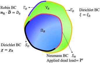 |
| | Fig. 3 Continuum deformable body in the reference configuration and applied boundary conditions. | |
Based on the principle of minimum free energy, the equilibrium state of the system is the state that minimizes the free energy of the system subject to the constraint imposed by the Maxwell's equations.
| | min{![[scr F, script letter F]](https://www.rsc.org/images/entities/char_e141.gif) [χ, [χ,![[P with combining tilde]](https://www.rsc.org/images/entities/b_char_0050_0303.gif) ]: (χ, ]: (χ,![[P with combining tilde]](https://www.rsc.org/images/entities/b_char_0050_0303.gif) ) ∈ ) ∈ ![[scr S, script letter S]](https://www.rsc.org/images/entities/char_e532.gif) and (χ, and (χ,![[P with combining tilde]](https://www.rsc.org/images/entities/b_char_0050_0303.gif) ) satisfies (4)}, ) satisfies (4)}, | (6) |
where
![[scr S, script letter S]](https://www.rsc.org/images/entities/char_e532.gif)
is the admissible set of functions over which the minimization is performed.
| |  | (7) |
Equilibrium equations of the system are the Euler–Lagrange equations associated with (6) which may be derived using standard variational calculus. Imposing boundary conditions χ = χb on SD, ξ = ξb on ΓD and ![[D with combining tilde]](https://www.rsc.org/images/entities/b_char_0044_0303.gif) ·nR = Db on ΓR, following system of governing equations and natural boundary condition should be solved simultaneously to determine the equilibrium state of the system:
·nR = Db on ΓR, following system of governing equations and natural boundary condition should be solved simultaneously to determine the equilibrium state of the system:
| |  | (8a) |
| | ∇·(−ε0JC−1∇ξ + F−1![[P with combining tilde]](https://www.rsc.org/images/entities/b_char_0050_0303.gif) ) = ) = ![[small rho, Greek, tilde]](https://www.rsc.org/images/entities/i_char_e0e4.gif) e in VR, e in VR, | (8b) |
| |  | (8c) |
| |  | (8d) |
| |  | (8e) |
where

is given as
| |  | (9) |
and

is the Piola–Maxwell stress
| |  | (10) |
We chose the following form of the internal energy density function:
| |  | (11) |
where
Welast is the strain energy function and can be chosen to appropriately model the constitutive nature of the materials being examined. Also,
ε is electric permittivity of material. Substituting
eqn (11) into equilibrium equations and writing all of the quantities in the current configuration, we have
| |  | (12a) |
| | div![[thin space (1/6-em)]](https://www.rsc.org/images/entities/char_2009.gif) d = ρe in Ω, d = ρe in Ω, | (12b) |
| | | div(σ + σ′MW) = 0 in Ω, | (12c) |
| | div![[thin space (1/6-em)]](https://www.rsc.org/images/entities/char_2009.gif) σMW = 0 in V\Ω, σMW = 0 in V\Ω, | (12d) |
| | | (σ + σ′MW)·n − te = 0 on Sn, | (12e) |
where
σ,
σ′
MW and
σMW are the Cauchy stress, Maxwell stress inside the body and Maxwell stress outside the body, respectively, and are given by
| |  | (13) |
| |  | (14) |
| |  | (15) |
3 A model to explain low d31 effect in conventional electrets
As already alluded to earlier, there has been compelling experimental indication for large value of (apparent) longitudinal piezoelectric coefficient d33 in electret foams.33 Theoretically also, Deng et al.59,60 have derived how the Maxwell stress, elastic heterogeneity and the presence of pre-existing charges or dipoles conspire to lead to this emergent longitudinal piezoelectric effect. We also remark that recently, Liu and Sharma61 have presented a homogenization theory for the effective properties of electrets. In this section, we examine a paradigmatical model of the conventionally fabricated electrets to explain the experimentally observed low values of emergent transverse piezoelectric coefficient d31.33 To do so, we analyze the in-plane stretching of the representative electret configuration shown in Fig. 4. This electret consists of two different materials on top and bottom which are referenced with subscripts “t” and “b”, respectively. Let X = XeX + YeY + ZeZ be representation of points in the Lagrange coordinates while points in Euler coordinates are denoted by x = xex + yey + zez. The domains of these two materials are:| | ΩRb = {(X, Y, Z) ∈ ![[Doublestruck R]](https://www.rsc.org/images/entities/char_e175.gif) 3: −H ≤ X ≤ αH, |Y| ≤ L, |Z| ≤ W}, 3: −H ≤ X ≤ αH, |Y| ≤ L, |Z| ≤ W}, | (16a) |
| | ΩRb = {(X, Y, Z) ∈ ![[Doublestruck R]](https://www.rsc.org/images/entities/char_e175.gif) 3: αH < X ≤ H, |Y| ≤ L, |Z| ≤ W}, 3: αH < X ≤ H, |Y| ≤ L, |Z| ≤ W}, | (16b) |
where |α| < 1 is a constant that parametrizes the interface between the two materials.
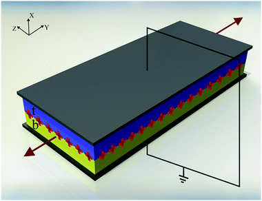 |
| | Fig. 4 Dielectric made of two different layers with embedded external charges under in-plane tension and short circuit boundary condition. | |
A layer of external charges with surface charge density q is inserted at the interface X = αH. As shown in Fig. 4, the two-material film is stretched in the Y direction.¶¶ Assuming plane-strain deformation, the deformation in Z direction vanishes. In what follows, we will refer to X and Y directions, respectively, as the thickness and in-plane directions. In the present case, the deformation in both these directions is uniform and the deformation gradient for both layers is given by:
| | | F = λ1ex ⊗ eX + λ2ey ⊗ eY + ez ⊗ eZ, | (17) |
where
λ1 and
λ2 are, respectively, the stretches in the thickness and in-plane direction. The incompressibility constraint (
J =
λ1λ2 = 1) implies that

. For the ease of notation, in what follows, we drop the subscript 1 and write
λ1 =
λ here and henceforth. In order to explore the implication of incompressibility constraint, we add one more term to the total free energy of the system given in
eqn (5):
| |  | (18) |
where
![[script L]](https://www.rsc.org/images/entities/char_e144.gif) a
a is a Lagrange multiplier. Also,
ΩR may be replaced with
ΩRt or
ΩRb to derive the equilibrium equations for each of the layers. Due to this modification of free energy,
eqn (9) and (13) are updated as
| |  | (19) |
| |  | (20) |
To model the mechanical behavior of the materials, we choose the incompressible neo-Hookean constitutive law and accordingly, the internal energy Welast may be expressed as:
| |  | (21) |
where
μ is the shear modulus. We remark that the choice of this particular hyperelastic constitutive model is not central to the main conclusions of this paper.
Two mechanically compliant electrodes are attached to the top and bottom surfaces of the electret structure and a short circuit electrical boundary condition is imposed (Fig. 4) to facilitate the definition of an apparent piezoelectric coefficient in response to mechanical stimulus. The objective is to determine the induced electric displacement as a result of the applied mechanical deformation or stress. The geometry of the structure and deformation assumptions ensures that the considered problem is essentially one-dimensional in nature with the electric field that varies only in the thickness direction. From eqn (12a) and (1) we have
| |  | (22) |
Substituting
eqn (22) and (21) into
(8) and using
eqn (11), equilibrium equations for each layer become:
| |  | (23a) |
| |  | (23b) |
and the boundary conditions are given as
| |  | (24a) |
| |  | (24b) |
for i = b and t.
γb = −1 and
γt = 1.
![[t with combining tilde]](https://www.rsc.org/images/entities/b_char_0074_0303.gif) ei
ei =
![[t with combining tilde]](https://www.rsc.org/images/entities/i_char_0074_0303.gif) eieY
eieY is the imposed traction (dead load) applied to each layer on the surfaces |
Y| =
L. As evident from the Maxwell's equations, the electric field is homogeneous within each layer. Therefore, eliminating
![[script L]](https://www.rsc.org/images/entities/char_e144.gif) a
a from system of
eqn (23), using boundary conditions
(24), the equilibrium equation for each layer reduces to:
| |  | (25) |
Given the short circuit boundary condition, the electric potential on the top and bottom surfaces remains zero and the electric potential at the interface is considered to be equal to an unknown value V, where V will be determined using the interface condition. Using these values for electric potential at boundaries and solving the Maxwell equation (12b) for each layer, electric potential difference is derived as
| |  | (26) |
where
ht =
λ(1 −
α)
H and
hb =
λ(1 +
α)
H are the deformed thicknesses of top and bottom layers, respectively. Considering the fact that surface charge density
q in the reference configuration will change to
λq in the current configuration, the interface condition is used to determine
V:
| |  | (27) |
Using
eqn (27) and substituting
eqn (26) into
(25), the traction in each layer required to maintain this deformation can be determined. We note that the electric displacement in each layer is also homogeneous and,
dt and
Dt are identified such that for the layer at the top we have
d =
dtex and
![[D with combining tilde]](https://www.rsc.org/images/entities/b_char_0044_0303.gif)
=
DteX. Substituting
eqn (26) into
eqn (22) we obtain:
| |  | (28) |
Dt is derived substituting
eqn (28) into
eqn (3):
| |  | (29) |
In order to measure the d31 piezoelectric coefficient of an actual piezoelectric material, an in-plane stretch similar to what is shown in Fig. 4 is applied. The piezoelectric coefficient can then be determined by measuring the change in the electric displacement in the thickness direction, DX, in response to the applied in-plane normal tractions where the following constitutive relation for piezoelectricity is used||||
| |  | (31) |
where
Dft =
Dt is the electric displacement after deformation and determined in
eqn (29) and
Dit =
Dt|
![[t with combining tilde]](https://www.rsc.org/images/entities/b_char_0074_0303.gif) e=0
e=0 is the electric displacement in the absence of an externally applied loading. In what follows, for any parameter
f, we define

. As evident from
eqn (29), in our considered electret structure (which is representative of conventionally fabricated electrets),
Dft −
Dit is zero. Therefore, the emergent
dapp31 piezoelectric coefficient is also zero. This is to be contrasted with the derivation for the large
dapp33 coefficient obtained for soft electrets.
59 Physically, when a mechanical load in thickness direction is applied to the electret structure being considered, deformation distributes non-uniformly. This non-uniformity of deformation results in an appreciable value for the
dapp33 piezoelectric coefficient. The material inhomogeneity is central to enable non-uniform deformation and the consequent non-zero
dapp33 coefficient. This fact it is reflected in the expression
***![[thin space (1/6-em)]](https://www.rsc.org/images/entities/char_2009.gif) 59,60
59,60 for
dapp33:
| |  | (32) |
In short, as long as deformation is non-uniformly distributed inside the material (
μt ≠
μb) a non-zero
dapp33 is predicted. However under in-plane stretch, the deformation is almost uniform everywhere in the electret.
The simple derivation in this section explains the root cause for low dapp31 coefficient and highlights that, to obtain a non-zero transverse piezoelectric response, a non-homogeneous deformation in the thickness direction must be engineered. This observation and our model also suggests the reason for a non-trivial d31 effect for electret polymer films observed by Zhang et al.34 They showed that electrets made of fluoroethylene propylene films with charged parallel-tunnel voids can have a very large d31. Based on our developed model, we speculate that the reason for this large piezoelectric coefficient is the specific design that they used which permits large deformation in the voids while polymer sections remain almost undeformed. For more clarification, consider Fig. 5a which shows a polymer foam with two parallel-tunnel voids in its undeformed configuration. Under an in-plane loading, the film undergoes a deformation similar to what is shown in Fig. 5b. The shape of voids alter significantly, but there is almost no deformation in the polymer sections and deformation in distributed non-uniformly between air voids and polymer sections leading therefore to a large bending piezoelectric effect.
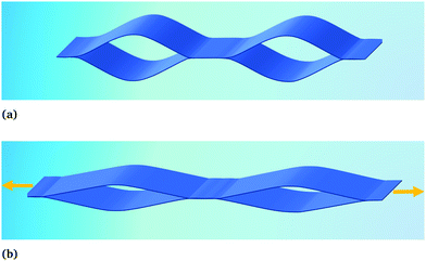 |
| | Fig. 5 Cross-section of a specific electret polymer film fabricated by Zhang et al.34 (a) Undeformed configuration (b) deformed configuration. | |
4 Flexure behavior of soft electrets
A non-trivial d31 piezoelectric coefficient is essential for a strong electromechanical response under flexure. To enable the design of electrets, and armed with insights from the preceding section, we perform a nonlinear analysis of the bending deformation of an electret structure. To our knowledge, there is no such analysis in the literature. Specifically we will consider both soft electret structure made of a single homogeneous material as well as composite electrets with two different materials. Specifically, we will, to a large extent possible, carry out a fully three-dimensional analysis as opposed to using the kinematics of a beam theory. Retaining the complexity of treating a three-dimensional object will allow us to show that the change in thickness (which is not captured in conventional beam theories) plays a crucial role in the nonlinear bending deformation of soft electrets. To distinguish between our analysis and a beam-type consideration, we will often refer our considered structure as a “block” rather than a “beam”. We remark here that in the purely mechanical context, flexure of a three-dimensional block was first analyzed by Rivlin.64 Our work is its generalization to the electromechanical case.
4.1 Bending of a homogeneous dielectric block under an external electric field
In order to elucidate the shortcomings of conventional soft dielectrics as a bending sensor and actuator, we first analyze the nonlinear flexure problem of a homogeneous dielectric block that is not an electret i.e. without embedded charges or dipoles. The reference and current configurations are shown in Fig. 6 where the three-dimensional representation of the block is due to the fact that we don't treat our structure as a “beam”. The block in the reference configuration is denoted by| | ΩR = {(X,Y,Z) ∈ ![[Doublestruck R]](https://www.rsc.org/images/entities/char_e175.gif) 3: |X| ≤ H, |Y| ≤ L, |Z| ≤ W}, 3: |X| ≤ H, |Y| ≤ L, |Z| ≤ W}, | (33) |
where H, L and W are the block's geometrical dimensions. As shown in Fig. 7, the Cartesian coordinate bases {eX, eY, eZ} are used to denote material points X. The cylindrical polar coordinates {er, eθ, ez} are employed to identify points in the current configuration. To describe bending of the block, we follow the approach presented by Rivlin64 who addressed the corresponding (purely) mechanical problem. The complete nonlinear boundary value problem (even in the purely mechanical case) is quite difficult. To simplify matter, we make the following kinematic assumption that the set of all material points initially located at any plane normal to eX are deformed to a set of points located in a curved cylindrical surface with constant radius and, similarly, the set of all material points initially located at any plane normal to eY are deformed to a set of points located in a plane with constant θ and there is no deformation in the Z-direction (see Fig. 7).
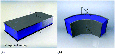 |
| | Fig. 6 Soft dielectric block under bending deformation and external electric field: (a) reference configuration (b) current configuration. | |
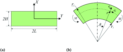 |
| | Fig. 7 Schematic of the coordinate systems used in the reference and current configurations. (a) Cartesian coordinates are used in the undeformed block. (b) A cylindrical coordinate system is employed for the deformed block. | |
A general deformation in the cylindrical coordinates can be expressed as
where
er =
er(
θ) and
θ =
θ(
Y). From
eqn (34), the deformation gradient is
| |  | (35) |
Imposing incompressibility constraint
†††J = 1 to the aforementioned class of deformation requires
r,
θ and
z to obey the following relations
| |  | (36) |
where
A and
B are unknown constants. We identify
r1 =
r(−
H) and
r2 =
r(
H). Associated with these deformations, we can write the deformation gradient as
| |  | (37) |
Similar to the stretch problem in Section 2, we employ the incompressible neo-Hookean constitutive law given in
eqn (21) and therefore the Cauchy stress
σ in the dielectric is given as
| | σ = μFFT − ![[script L]](https://www.rsc.org/images/entities/char_e144.gif) aI. aI. | (38) |
Ignoring non-radial components of electric field for simplicity and using
eqn (1) and (12a), electric displacement and polarization can be written in terms of the electric potential as follows:
| |  | (39) |
Consequently, Maxwell's equations and the boundary conditions in the absence of external charges but with the block subjected to a potential difference are
| |  | (40) |
Electric field in the current configuration is determined by solving
(40):
| |  | (41) |
Having electric field, we can calculate Maxwell stress from
(14). Then total stress is obtained as
| | σ + σ′MW = σrr*er ⊗ er + σθθ*eθ ⊗ eθ + σzz*ez ⊗ ez − ![[script L]](https://www.rsc.org/images/entities/char_e144.gif) aI, aI, | (42) |
where
| | 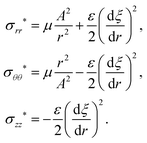 | (43) |
Equilibrium
eqn (12c) in the radial direction can be written as:
| |  | (44) |
To simplify the solution, we express
A and
B in terms of
r1 and
r2. Using equations
r1 =
r(−
H),
r2 =
r(
H) and
eqn (36) we have
| |  | (45) |
To solve the equilibrium equation, we impose the following boundary conditions:
| | tr = (σ* − ![[script L]](https://www.rsc.org/images/entities/char_e144.gif) aI)er = 0 at r = r1 and r = r2, aI)er = 0 at r = r1 and r = r2, | (46a) |
| |  | (46b) |
where
M is the bending moment over unit width of the block and
tr is the surface traction for the surface with unit normal
er.
Integrating eqn (44) and using first equation of (46a), the Lagrange multiplier ![[script L]](https://www.rsc.org/images/entities/char_e144.gif) a can be determined to be
a can be determined to be
| |  | (47) |
For future expedience, we also introduce the radial stretch
λ and radius ratio
Λ:
| |  | (48) |
With the relation for the Lagrange multiplier at hand, using relations
(45) and (48), we can solve the second boundary condition in
(46a) for
λ. With the substitution of the stretch in
eqn (46b), all quantities can be expressed in closed-form in terms of
Λ. The stretch and bending moment can then be derived to be:
| |  | (49) |
| |  | (50) |
We introduce

as a representation for the curvature. Curvature
![[small kappa, Greek, macron]](https://www.rsc.org/images/entities/i_char_e0cb.gif)
will be positive if
r2 >
r1 and
vice versa. The ratio
Λ in
(48) can be easily related to curvature through relation:
| | Λ = 1 + ![[small kappa, Greek, macron]](https://www.rsc.org/images/entities/i_char_e0cb.gif) . . | (51) |
From the nonlinear relation
(49), we observe that the stretch depends on both the curvature and the applied electric field. However, the bending moment is independent of the applied potential difference and the effect of electric field on curvature emerges
only through a change of thickness. If the thickness in the deformed configuration remains unchanged from the reference configuration, then the electric field will not have any impact on curvature since curvature bending moment relation
(50) is independent of the electric field.
In many practical applications, thickness of the film is much smaller than the radius of curvature even when the film undergoes large deformation. In such a case, |![[small kappa, Greek, macron]](https://www.rsc.org/images/entities/i_char_e0cb.gif) | ≪ 1. This condition is also valid for thick blocks under small deformations. It is therefore instructive to linearize (50) and (49) for the cases with |
| ≪ 1. This condition is also valid for thick blocks under small deformations. It is therefore instructive to linearize (50) and (49) for the cases with |![[small kappa, Greek, macron]](https://www.rsc.org/images/entities/i_char_e0cb.gif) | ≪ 1. Ignoring higher order terms, stretch and bending moment can then be expressed as
| ≪ 1. Ignoring higher order terms, stretch and bending moment can then be expressed as
| |  | (52) |
| |  | (53) |
We remark that in the flexure problem discussed in this section as well as the stretch problem discussed in Section 3, in absence of mechanical loading, deformation is only caused by the applied electrical field. Since there is no kinematic constraint against the change of thickness in the models used for both the bending and stretch problems, the derived change of thickness in response to the applied electrical field should be the same for both models. Indeed,
eqn (52) is exactly the same as
(25) when the applied traction is zero. Also, several other interesting conclusions may be drawn by a careful consideration of
eqn (52) and (53):
(1) Eqn (52) is independent of curvature ![[small kappa, Greek, macron]](https://www.rsc.org/images/entities/i_char_e0cb.gif) and the external electric field is the only reason for the change of thickness.
and the external electric field is the only reason for the change of thickness.
(2) Eqn (53) is independent of V. Although the value of ![[small kappa, Greek, macron]](https://www.rsc.org/images/entities/i_char_e0cb.gif) depends on the thickness of the block in the deformed configuration, and alteration in the external electric field will change the thickness and consequently curvature but ignoring the effect of external electric field on the thickness of the block will lead to the complete de-correlation of the curvature of the film and the external electric field.
depends on the thickness of the block in the deformed configuration, and alteration in the external electric field will change the thickness and consequently curvature but ignoring the effect of external electric field on the thickness of the block will lead to the complete de-correlation of the curvature of the film and the external electric field.
(3) Even if we account for the change of the thickness due to external field and its effect on the curvature, their relation is quadratic (see eqn (52)). This observation implies that a change in the direction of the electric field will not change the direction of deformation thus limiting the application of ordinary soft dielectrics as bending actuators.
(4) Eqn (53) shows that in the absence of bending moment (M = 0) curvature ![[small kappa, Greek, macron]](https://www.rsc.org/images/entities/i_char_e0cb.gif) is zero. This, in turn, signifies that no matter how large the applied electric field, flexure will not ensue in absence of an applied mechanical bending moment.
is zero. This, in turn, signifies that no matter how large the applied electric field, flexure will not ensue in absence of an applied mechanical bending moment.
These aforementioned points emphasize that ordinary soft dielectrics are unsuitable, at least if used naively, as bending sensors and actuators. We will show in the next section that electrets offer a rather rich set of avenues to tweak flexure response of soft dielectrics.
4.2 Bending deformation of a homogeneous block with embedded charges—an electret
We now turn our attention to the problem that is at the heart of the central goal of the manuscript. We reconsider the nonlinear flexure problem of a soft dielectric block but now containing a distributed (and embedded) immobile layer of charge.‡‡‡ We consider such a layer of charge with surface density q to be located at the plane X = Xch in the reference configuration (Fig. 8) where Xch = αH and α is an indicator of the position of the charge layer. This parameter can take values between −1 and 1. The plane containing electric charges will deform to a curved surface with the radius r = rch. The total charge inside the dielectric is conserved and with that, the charge density in the current (deformed) configuration may be expressed as| |  | (54) |
where δ(·) is the one-dimensional Dirac delta function and A was defined earlier in eqn (36).
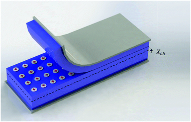 |
| | Fig. 8 A layer of charges is embedded in a soft dielectric. | |
Invoking the premise that the electric field only exists in the radial direction, using (12a) and (12b), and employing the short circuit boundary condition, the electric field in the current configuration is obtained as
| |  | (55) |
where
![[script letter H]](https://www.rsc.org/images/entities/char_e142.gif)
(·) is the Heaviside step function. We defer for now the discussion on the influence of external voltage and the actuator mode application of this structure. As done in prior sections, the stretch can be evaluated analytically in terms of the radius ratio
Λ and other properties of the dielectric block:
| |  | (56) |
where

. The coefficients
Cij depend on
Λ and
α and their complete expressions are recorded in Appendix A. The bending moment necessary to maintain the desired deformation in terms of radius ratio using
(46b) is
| |  | (57) |
Eqn (57) should be contrasted with
eqn (50). In the case of an electret, the electric field created by the embedded charges influences the bending deformation of the block not only through the change of the thickness but also through a direct effect on the bending moment-curvature relation. In order to further clarify the effect of embedded charges on the bending deformation of thin films, we express the stretch and bending moment in terms of only the leading order terms of
![[small kappa, Greek, macron]](https://www.rsc.org/images/entities/i_char_e0cb.gif)
:
| | λ4 = λ04 + D11![[small kappa, Greek, macron]](https://www.rsc.org/images/entities/i_char_e0cb.gif) + o( + o(![[small kappa, Greek, macron]](https://www.rsc.org/images/entities/i_char_e0cb.gif) ), ), | (58) |
| |  | (59) |
where
| |  | (60) |
| |  | (61) |
Coefficients Dij are recorded in the Appendix A. Both eqn (59) and (58) depend on ![[small kappa, Greek, macron]](https://www.rsc.org/images/entities/i_char_e0cb.gif) and
and ![[q with combining macron]](https://www.rsc.org/images/entities/i_char_0071_0304.gif) 0. The simple implication of this observation is that the coupling between the mechanical and electrical state of the dielectric block is significantly more intricate and stronger in electret structures as compared to ordinary dielectrics. Notably, any change in the amount of charge or the position of charge layer will change the bending moment required to cause a specific value of curvature even if we were to ignore changes in the thickness. This is in contrast to what we observed in eqn (53) for the small-deformation case of a thin homogeneous film under an external applied electric where the effect of the external voltage only emerges from a change in the thickness.
0. The simple implication of this observation is that the coupling between the mechanical and electrical state of the dielectric block is significantly more intricate and stronger in electret structures as compared to ordinary dielectrics. Notably, any change in the amount of charge or the position of charge layer will change the bending moment required to cause a specific value of curvature even if we were to ignore changes in the thickness. This is in contrast to what we observed in eqn (53) for the small-deformation case of a thin homogeneous film under an external applied electric where the effect of the external voltage only emerges from a change in the thickness.
Eqn (59) can be solved for ![[small kappa, Greek, macron]](https://www.rsc.org/images/entities/i_char_e0cb.gif) to derive an approximate linear relation for the curvature in terms of the bending moment
to derive an approximate linear relation for the curvature in terms of the bending moment
| |  | (62) |
A rather interesting property of the electret may be realized from
(62); unless the charge layer is
exactly located in the middle of the block (
α = 0), a nonzero curvature will develop even in the
absence of external mechanical loading. In other words, existence of Maxwell stress in non-symmetric block (block in which charge layer in not located in the mid-plane) leads to bending of the block. Setting
M = 0,
eqn (62) may be used to ascertain that a nonzero curvature exists in the structure even in the absence of any mechanical loading.
In addition to embedded charges, we can also consider the effect of an external voltage to investigate actuator application of the electret structure. For this purpose, the Maxwell's equations are solved using the embedded charge given in (54) and boundary condition used in (40) to derive the electric field:
| |  | (63) |
Following a similar process as before, the mechanical boundary conditions are imposed to determine the stretch in terms of radius ratio and then all quantities are expressed in terms of the radius ratio. Since the process is straightforward but the resulting equations are rather long, we avoid listing them here and the details may be found in Appendix B. After deriving the nonlinear bending moment radius ratio relation, we linearize this relation for |
![[small kappa, Greek, macron]](https://www.rsc.org/images/entities/i_char_e0cb.gif)
| ≪ 1 and derive an expression similar to
(59) with modified values for
D12 and
M0. Relation for
D12 is given in
eqn (A.9). In order to provide insights into the bending behavior of electret under external voltage (in absence of any mechanical loading) we simply update the expression of
M0 presented in
eqn (61). The modified
M0 may be derived to have the following form:
| |  | (64) |
where

. An intriguing implication from
(64) is that in the presence of external electric field and absence of mechanical loading, a non-zero value for curvature is obtained—even for symmetric electrets (
α = 0). Moreover, this curvature depends on the value of external electric field and any change of the external field will also alter the curvature. As will be discussed in the next section, this behavior may be interpreted as converse bending piezoelectric behavior.
4.3 Identification of the apparent flexoelectric and d31 piezoelectric coefficients in electrets
As shown in the prior section, if a fixed bending moment is maintained, an electric field can change the curvature of the electret structure and conversely, a change in curvature can lead to a change in the electric field. This can be made more explicit by examining the electric displacement. For a short circuited electret structure, ![[D with combining tilde]](https://www.rsc.org/images/entities/b_char_0044_0303.gif) may be determined by using eqn (55), (39) and (3):
may be determined by using eqn (55), (39) and (3):| |  | (65) |
Electric displacement in eqn (65) depends on Λ, signifying that electric displacement changes with the change of curvature. Using Taylor series for small values of ![[small kappa, Greek, macron]](https://www.rsc.org/images/entities/i_char_e0cb.gif) we can elucidate a linear relation between the change of electric displacement and curvature:
we can elucidate a linear relation between the change of electric displacement and curvature:| |  | (66) |
In the present context, we may identify the initial state as the zero curvature (flat) state and the curved state as the final deformed state of the bending. Denoting Df and Di, respectively, to represent the electric displacement in the final and initial states, we can write Di as
The linear relation between curvature and electric displacement, or polarization, is a tell-tale signature of flexoelectricity. In an experimental setting, flexoelectric coefficient of a material can be determined by measuring the electric current generated during bending deformation. We use such a gedanken on these lines to define an apparent (and emergent) flexoelectric coefficient for the electret structure.66
Interchangeably, and somewhat ambiguously, the same basic logic may also be interpreted as an emergent d31 piezoelectric coefficient. However, this requires some further nuanced discussion. As already discussed briefly in the introductory section, because the average strain is zero in bending, a (net) electric polarization is not generated from the bending deformation of a single layer piezoelectric film unless a bimorph configuration is used. Bending of a piezoelectric bimorph with opposite poling directions (shown in Fig. 9) leads to the development of a non-zero (net) electric polarization inside the material. In addition, a uniform external electric field can cause bending in the bimorph with opposite poling directions. We remark that an electret with embedded charges is similar to a bimorph with opposite poling directions. So, in order to interpret the flexure of electrets in terms of emergent piezoelectric or interchangeably, flexoelectric response, we must compare it with either a piezoelectric bimorph or a homogeneous material with flexoelectric effect. Since it is not possible to analytically solve a non-linear three-dimensional bending problem of a flexoelectric or piezoelectric block, we use a simple linear piezoelectric or flexoelectric Euler-beam theory to find the correlation between mechanical loading and induced charge. Then, this correlation is compared with the results of our nonlinear model for electrets to suggest expressions for the apparent flexoelectric and piezoelectric coefficients.
 |
| | Fig. 9 Piezoelectric bimorph made of two layers of piezoelectric materials with different poling directions. (a) Undeformed configuration (b) deformed configuration. | |
Apparent piezoelectric coefficient.
The definition of the apparent piezoelectric coefficient requires the solution to the bending problem of a bimorph. The derivation is recorded in Appendix C and specifically the central result used in this section appears in (C.17). In contrast to the piezoelectric beam model, our model for the flexure of an electret is nonlinear and three-dimensional. To relate them and derive apparent piezoelectricity as would be measured in experiments, we introduce the notion of average curvature 〈κ〉 as| |  | (67) |
Apparent bending stiffness κappb and apparent piezoelectric coefficient dapp31 of the electret structure can therefore be defined as| |  | (68) |
| |  | (69) |
Eqn (67) can be used to replace ![[small kappa, Greek, macron]](https://www.rsc.org/images/entities/i_char_e0cb.gif) with 〈κ〉 in eqn (62) and extract the average curvature of the block and the electric displacement (66) in terms of bending moment. Then, substituting eqn (59) into eqn (69) we have:
with 〈κ〉 in eqn (62) and extract the average curvature of the block and the electric displacement (66) in terms of bending moment. Then, substituting eqn (59) into eqn (69) we have:| |  | (70) |
It is clear that the best position for the charge layer, which maximizes the emergent and apparent piezoelectric coefficient, is exactly in the middle of the block. Furthermore, there is an inverse relation between material stiffness and the apparent dapp31 piezoelectric coefficient of the electret block.
Apparent flexoelectric coefficient.
To alternatively interpret the electret structure in terms of flexoelectricity, we must first define an apparent flexoelectric coefficient. This requires the solution for the bending problem of a homogeneous flexoelectric beam and the relevant derivation is recorded in Appendix D. The key result we use in this section is eqn (D.10) and based on this, we may define the apparent flexoelectric coefficient fapp of the electret structure as| |  | (71) |
Substituting eqn (66) into (71), the apparent flexoelectric coefficient is derived as| |  | (72) |
The apparent emergent flexoelectric coefficient in (72) is directly proportional to the thickness of the block and therefore an increase of the thickness would appear to be a way to increase the flexoelectric coefficient. This notion is somewhat deceptive however. We must recognize that increasing the thickness will also require substantially larger mechanical energy to bend the structure (which scales with H3). In addition, it should be mentioned that the reason for negligible flexoelectric effect in conventional materials at large scales is that in this effect, polarization is proportional to strain gradient and there is an inverse relation between magnitude of strain gradient and characteristic size-scale of the problem. However, for the electret structure under consideration, the apparent flexoelectric coefficient is not a structure-independent constant as in the case of a non-electret material. The apparent flexoelectric coefficient of the electret structure increases with increasing size scale which compensates for the decrease of strain gradient with increasing size scale and in this sense it leads to a size-independent effect. Finally, we remark that, in the present setting of a simple homogeneous electret structure, the maximum apparent flexoelectric coefficient corresponds to the electret in which the charge layer is located exactly in the middle of the block (α = 0).
Energy conversion ratio.
In addition to flexoelectric and piezoelectric coefficients, a physically meaningful measure to study is the effectiveness of the electret material to convert applied mechanical energy into electric energy as compared with conventional piezoelectric materials. For this purpose, we compare the amount of energy required to induce an identical amount of electric charge at the electrodes. Electric charge induced at electrodes for the electret structure is Df − Di and can be computed from eqn (66). For the appropriate interpretation, this value may be equated to the induced charge on the electrode surface of the comparison piezoelectric material—which is equal to d given in eqn (C.16). For this comparison, the bending moment Mpiezo which should be applied to piezoelectric material in order to induce d = Df − Di can be determined from (66) and (C.16):| |  | (73) |
where b31 is the piezoelectric coefficient introduced in (C.1) and ε33 is the dielectric coefficient in the poling direction of material. The mechanical energy required to induce this amount of charge is obtained through the work done on the system by means of the applied bending moment. The work done by the applied bending moment on piezoelectric material with unit volume is equal to  where κb is given in (C.14). Substituting the value of the bending moment from (73), Wpiezo can be determined as
| |  | (74) |
Also, using eqn (59), the work done by the applied mechanical loading to deform a unit-volume electret from an initially flat configuration to deformed configuration is given as| |  | (75) |
Substituting eqn (57) and (36) into eqn (75), and using eqn (56), (45) and (48), Welectret can be written as| |  | (76) |
With these required energetic quantities at hand for both the piezoelectric and electret materials, we define energy conversion ratio (ECR) as| |  | (77) |
If we consider a single crystal barium titanate piezoelectric film with ε33 = 109ε0, d31 = −34.5 pC N−1 and c11 ≈ 124 GPa67 and a symmetric polypropylene (PP) electret with q = 10−3 C m−2, μ = 0.95 MPa and ε = 2.35ε0,68 we will have ECR = 0.23. This implies that in barium titanate, the mechanical energy required to produce a given amount of electrical energy is almost four times less than that of PP electret. However, although in this example, the ECR value for electret is smaller than 1 and energetically it is more favorable to use barium titanate film, soft electrets can tolerate much larger deformation. Furthermore, it is evident that  and that increasing the amount of embedded charges or using softer materials can be used to increase ECR.
4.4 The effect of embedded dipoles on the apparent flexoelectric and d31 piezoelectric behavior
In addition to embedded charges, embedded dipoles are also used in electrets. The widely used soft cellular polymer foams may be considered to consist of embedded dipoles in voids of a soft matrix. As shown in Fig. 10, these polymer foams are soft porous materials with huge number of entrapped air voids such that volume fraction of voids are often more than 50 percent. Trapped charges on the surfaces of voids create large dipoles inside the foam (Fig. 10a). In some sense, this is analogous to large dipoles created by the charge layer in the composite of the preceding section and the top and bottom electrodes. In this section, we use a layered structure to model voided film where there is a layer of air between two layers of polymer (Fig. 10b). Embedded charges with surface charge densities q and −q exist at the interface of the air layer and polymer layer to mimic dipoles. Two parameters α1 and α2 have been introduced to identify position of charge layers. The solution to the bending problem of an electret made of two layers of different materials is given in Appendix E. This can be extended for a soft dielectric block made of three different layers. We avoid giving details of the derivation for this case since the process is identical to what was presented before. Ignoring higher order terms and following the same notation introduced in eqn (66), electric displacement for this structure is given as:| |  | (78) |
where εr = ε/ε0 and Ha is the thickness of air layer. Note that Df − Di for all three layers is the same. In charged polymers, dipoles are almost uniformly distributed inside the material. It is clear that for a symmetric distribution of embedded dipoles (α2 = −α1), change in the electric displacement will be zero and bending will not induce any change in the charges induced at the electrodes. This explains the reason for the observation of small d31 in charged polymer foams. However, there is a simple way to obtain desirable values for α1 and α2 and a non-symmetric distribution of dipoles. The basic ideas are illustrated in Fig. 11a. Essentially, electret structures can be combined with non-electret material (i.e. ordinary dielectric) to facilely create the asymmetry needed to obtain a non-trivial d31. Although we do not present further details, a slight modification to the current models (developed so far) may be easily used to find the apparent properties of a film composed asymmetric electret structures shown in Fig. 11b.
 |
| | Fig. 10 (a) Existence of external dipoles in polymer foams. (b) A layered structure is used to model charged porous polymer. Constants α1 and α2 show the positions of charge layers. | |
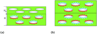 |
| | Fig. 11 Methods to break symmetry in distribution of dipoles. (a) Attachment of a non-electret material to an electret material. (b) Attachment of two asymmetric electrets. | |
Upon substituting eqn (78) into eqn (71) and (69) the apparent flexoelectric coefficient and apparent piezoelectric coefficient can be derived:
| |  | (79) |
| |  | (80) |
where
μ in
(80) is an effective shear modulus which accounts for both polymer section and air voids. Qualitatively, the results do not differ in any significant manner from the previous section.
5 Results and discussion
The nonlinear models presented in the preceding sections can be used to obtain several interesting insights into the design of flexoelectricity and d31 piezoelectricity in soft electrets. However, first, in order to highlight the similarities and differences between conventional dielectrics and electret materials, we present the bending deformation behavior of an ordinary soft dielectric in Fig. 12. Relations (49) and (50) have been used to draw this figure. In Fig. 12a we illustrate the change in thickness of a soft dielectric block under the action of a combined bending moment and electric field. As expected, Fig. 12a shows that applying a constant external electric field leads to the thinning of the block. As it was discussed earlier in preceding sections, this change of thickness leads to emergence of a coupling between electric field and curvature of the block. Change of curvature in response to applied electric field is shown in Fig. 12b to investigate possibility of using ordinary dielectrics as bending actuator. We introduce the following dimensionless measure of the curvature  and use this quantity throughout the section. Fig. 12b shows that for fixed non-zero values of bending moment, increasing external field results in the increase of the curvature observed in the block. However it is evident, from this figure, that if the applied bending moment is zero, electric field alone will not induce a change in curvature. In the other words, some pre-existing curvature should be present to observe a coupling between the curvature and electric field for ordinary dielectrics. This is one of limitations of dielectric actuators. Another one is that the electromechanical coupling in the non-electret soft dielectric block is generated from Maxwell stress effect which, by nature, is quadratic with respect to electric field. Accordingly, a change in the direction of the applied electric field will not alter the direction of the induced curvature.
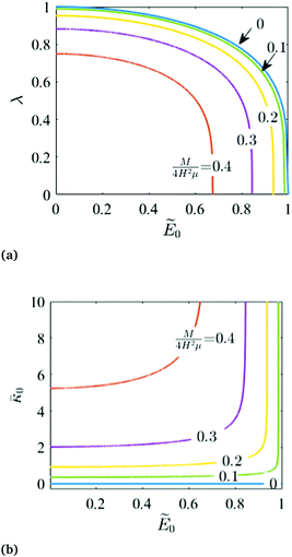 |
| | Fig. 12 Behavior of soft dielectric block under the action of a combined bending moment and electric field. (a) Change of thickness in response to applied electric field and bending moment. (b) Coupling between electric field and curvature. | |
Flexure behavior of electret with a single layer of embedded charge
The formulation presented in Section 4.2 is used to analyze the flexure behavior of the electrets with embedded charges. Eqn (56) and (57) are used to plot the variation of the dimensionless bending moment with dimensionless curvature in Fig. 13 for a short circuited electret with asymmetric distribution of charges (α = 0.5). As evident, the presence of the charge has a profound effect on the bending moment–curvature relation. In particular, the curvature does not vanish even when the applied bending moment is zero. This is due to the asymmetric distribution of charges and consequently a non-uniform state of Maxwell stress inside the material.
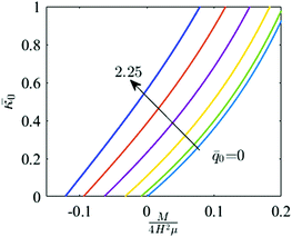 |
| | Fig. 13 Effects of external charges on the curvature of the block for α = 0.5. | |
As discussed earlier, when two layers of piezoelectric materials with opposite poling directions are exposed to an external electric filed in the thickness direction; the d31 converse piezoelectric effect leads to bending. The same behavior is seen in electrets. Using (B.12), Fig. 14 shows that an electret made of a dielectric with a layer of charge with ![[q with combining macron]](https://www.rsc.org/images/entities/i_char_0071_0304.gif) 0 = 0.225 bends in response to external electric field and in absence of any external mechanical load. This value of electric charge will be attainable upon insertion of a layer of electric charge with q = 10−3 C m−2 into a PP film with μ = 0.95 MPa and ε = 2.35ε0.68 Furthermore, Fig. 14 shows that the direction of curvature depends on the direction of applied field. This linear relation is in contrast with the quadratic behavior of an ordinary dielectric under external voltage in the absence of external charges and proves the capability of soft electrets to be used as a bending actuator. The emergent d31 effect is stronger when the charge layer is in the middle of the block (α = 0).
0 = 0.225 bends in response to external electric field and in absence of any external mechanical load. This value of electric charge will be attainable upon insertion of a layer of electric charge with q = 10−3 C m−2 into a PP film with μ = 0.95 MPa and ε = 2.35ε0.68 Furthermore, Fig. 14 shows that the direction of curvature depends on the direction of applied field. This linear relation is in contrast with the quadratic behavior of an ordinary dielectric under external voltage in the absence of external charges and proves the capability of soft electrets to be used as a bending actuator. The emergent d31 effect is stronger when the charge layer is in the middle of the block (α = 0).
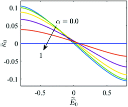 |
| | Fig. 14 Converse piezoelectric behavior of electret with ![[q with combining macron]](https://www.rsc.org/images/entities/i_char_0071_0304.gif) 0 = 0.225. 0 = 0.225. | |
Energy harvesting application and emergent properties of electrets
The possibility of using electrets as sensors and their apparent and emergent piezoelectric/flexoelectric coefficients are studied in Fig. 15–18. Bending of a short circuited electret changes the electric field and electric polarization inside the material. In order to show this electro-mechanical coupling, we use eqn (65) to plot the change of electric displacement versus the dimensionless curvature in Fig. 15 for a homogeneous dielectric with an embedded layer of electric charge. The change of the electric displacement, and hence the capability to generate current, in response to changes in curvature illustrates the potential application of the electret structure as an energy harvester and sensor. Also, for small curvatures a linear change is observed in the electric displacement. Since the flexoelectric behavior is the linear development of polarization in response to imposed curvature in vicinity of zero curvature (small deformation), this change of the electric displacement and consequently electric polarization seen in electret can be interpreted as an emergent flexoelectric-like behavior and this effect is stronger when charge layer is closer to the middle surface of the block. Plotting the apparent flexoelectric coefficient in Fig. 15b using the definition in eqn (72), we see that a flexoelectric coefficient of the order of fapp(ε − ε0) ≈ 10−8 C m−1 is possible for an electret with micro scale thickness and with a realistic surface charge density q = 10−3 C m−2.
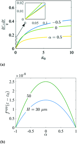 |
| | Fig. 15 Flexoelectric behavior of the electret. (a) Charge harvested in the bending deformation of a short circuited electret. (b) Apparent flexoelectric coefficient of a homogeneous film with ![[q with combining macron]](https://www.rsc.org/images/entities/i_char_0071_0304.gif) 0 = 0.225. 0 = 0.225. | |
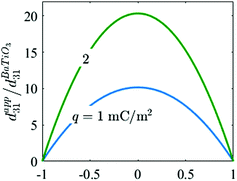 |
| | Fig. 16 Apparent piezoelectric coefficient for a PP film with a layer of external charge inserted versus position of charge layer. | |
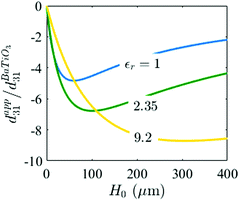 |
| | Fig. 17 Apparent piezoelectric coefficient of a polymer film with embedded dipoles attached to another material free of dipoles with thickness H0. | |
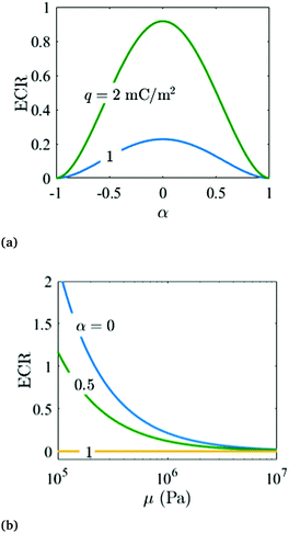 |
| | Fig. 18 ECR coefficient to compare energy efficiency of electret with a barium titanate piezoelectric material. (a) ECR versus α for an electret with μ = 1 MPa and ε = 2.35ε0. (b) ECR versus shear modulus of electret for an electret q = 10−3 C m−2. | |
Fig. 16 shows the apparent d31 piezoelectric coefficient for a PP film with μ = 0.95 MPa with one layer of external charges using eqn (70). The apparent piezoelectric coefficient is found to be roughly ten times more than the corresponding value of barium titanate where 
![[thin space (1/6-em)]](https://www.rsc.org/images/entities/char_2009.gif) 67 and q = 1 mC m−2. While a high longitudinal piezoelectric coefficient for electrets has been already reported, this is the first prediction for such a large d31 value.
67 and q = 1 mC m−2. While a high longitudinal piezoelectric coefficient for electrets has been already reported, this is the first prediction for such a large d31 value.
In order to present the piezoelectric coefficient for a polymer with embedded dipoles, we consider a polymer foam with H = 30 μm and assume an air volume fraction of 50% or Ha = H (see Fig. 10). Initially dipoles have a symmetric distribution and the apparent piezoelectric coefficient is zero. Another piece of the identical polymer film of thickness H0, free of dipoles, is attached to the electret material (Fig. 11a). A shear modulus of μ = 1 MPa is assumed. The apparent piezoelectric coefficient for this structure versus thickness of the attached film is shown in Fig. 17 using eqn (80). The apparent piezoelectric coefficient increases with H0 until it obtains an optimum. The thickness which maximizes the apparent piezoelectric coefficient of the structure depends on the electric permittivity of the material and can be determined mathematically from: H0 = 2H + Ha(εr − 1).
In what follows, we use eqn (74), (76) and (77) to plot the ECR coefficient to compare energy conversion efficiency of an electret with a single layer of embedded charge to a homogeneous barium titanate piezoelectric. Barium titanate properties are considered as ε33 = 109ε0, d31 = −34.5 pC N−1 and c11 ≈ 124 GPa.67 As expected from prior results, Fig. 18a shows that ECR is maximized when the charge layer is located in the middle of the block. Furthermore, increasing the amount of surface charge density to 2 mC m−2 in an electret with a shear modulus 0.95 MPa will perform almost as well as barium titanate. Given that the electret is capable of orders of magnitude larger deformation, this comparison is quite astounding. Another avenue to obtain an higher ECR is suggested in Fig. 18b. The figure shows that softer electrets have higher ECR and an order of magnitude reduction in the shear modulus can dramatically increase the ECR.
6 Concluding remarks
Soft electret materials have been proposed as candidates for applications that require a strong electro-mechanical coupling as well as a capability for large deformation. Although a large apparent d33 piezoelectric coefficient has been reported for some soft polymer foam electrets, their d31 piezoelectric coefficient is rather small and the electro-mechanical coupling in flexure motion is quite weak. In this work we provide a physical rationale for observed low value of d31 in typical electrets. We analyze the behavior of electrets under bending deformation and pathways to obtain substantive d31 piezoelectricity or alternatively a flexoelectric like behavior, are suggested. Our central formulation is quite general and may be used, beyond the simple examples studied in the present work, for future numerical design and optimization of flexoelectric and bending piezoelectric electrets. We obtain the following insights:
(1) The microstructure of electrets must lead to non-trivial inhomogeneous deformation for the emergence of d31 piezoelectric effect.
(2) Ordinary dielectrics may not fit applications that require a linear electro-mechanical coupling in bending deformation. The reason is that some pre-existing curvature is required to observe coupling between externally applied electric field and curvature in dielectrics. Also, even when pre-existing curvature is present, this coupling only depends on the magnitude of electric field and it is independent of the direction of the field.
(3) A converse d31 piezoelectric behavior is obtained for an electret with one layer of embedded charges, implying that an externally applied electric field can bend this electret and a change in the direction of electric field will also alter the direction of the deformation. In addition, bending of such an electret will also alter the electric field and polarization inside the material and this change of polarization can be interpreted as either a d31 piezoelectric effect or alternatively, flexoelectricity.
(4) We estimate the apparent flexoelectric and d31 piezoelectric coefficient for electrets and suggest approaches to improve the overall energy conversion ability of the material.
Conflicts of interest
There are no conflicts to declare.
Appendices
A. Coefficients Cij, Dij and Eij introduced in Section 4
The coefficients Cij are defined as:| |  | (A.1) |
| | 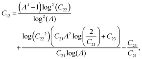 | (A.2) |
| |  | (A.3) |
| | | C21 = 1 + Λ2 + α(Λ2 − 1), | (A.4) |
| |  | (A.5) |
| | | C23 = (1 − α)(1 − Λ4), | (A.6) |
| |  | (A.7) |
Coefficients Dij are given as
| |  | (A.8) |
| | 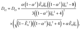 | (A.9) |
| |  | (A.10) |
| |  | (A.11) |
In
eqn (A.9) for coefficient
D12, the contributions of both electric field and electric charges have been considered. So, the electric field
Ẽ0 should be set to zero in the relation
(A.9) to obtain coefficient
D12 used in
eqn (59).
Coefficients Eij are given as
| |  | (A.12) |
| | | E13 = (C21 − 2)(3C21 + 2), | (A.14) |
| | | E14 = (1 − α)(Λ2 − 1)(3 + 5Λ2 + 3α(Λ2 − 1)), | (A.15) |
| |  | (A.16) |
| |  | (A.17) |
| |  | (A.18) |
| | 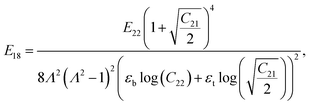 | (A.19) |
where
| |  | (A.20) |
| | 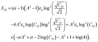 | (A.21) |
B. Derivation of relation between bending moment and curvature for electret under external voltage introduced in Section 4.2
In order to determine the relations for stretch and bending moment in terms of curvature for the electret shown in Fig. 8 which is also under an external electric voltage, eqn (63) is substituted into eqn (43) to determine the stresses. The boundary condition given in second equation of (46a) can be written as:| | | F11 + F12λ2 + F13λ4 = 0, | (B.1) |
where| |  | (B.2) |
| |  | (B.3) |
| |  | (B.4) |
| |  | (B.5) |
Also, eqn (63) is used to write the boundary condition (46b) as| |  | (B.6) |
where| |  | (B.7) |
| |  | (B.8) |
| |  | (B.9) |
| |  | (B.10) |
We now simply solve eqn (B.1) for stretch λ and substitute the solution into (B.6). This will yield the relation between bending moment and curvature. Since the algebra is simple and the non-linear bending moment curvature relation is extremely tedious, we only present its Taylor series expansion for small ![[small kappa, Greek, macron]](https://www.rsc.org/images/entities/i_char_e0cb.gif) :
:| |  | (B.11) |
where M0 and D12 are given by (64) and (A.9), respectively. As a result, curvature induced in the block because of electrical loading and in absence of bending moment is determined as| |  | (B.12) |
C. Solution for bending problem of piezoelectric bimorph beam introduced in Section 4.3
In this section, we present the solution to the bending problem of a piezoelectric bimorph. The final result is necessary to define the apparent piezoelectric coefficient for the electret problem considered in Section 4.3. Using Euler beam kinematics, we find a relation for piezoelectric coefficient in terms of applied bending moment. Consider Fig. 9 which shows a material composed of two layers of the same piezoelectric material with opposite poling directions. Let x and z be, respectively, axial and thickness directions of the beam. Axial elastic modulus of the material is denoted by c11 and both layers have the same thickness H. We assume a unit width for the beam and the length of the beam is 2L. This beam is deformed in response to bending moment M applied at the two ends. Short circuit boundary condition is imposed using two mechanically compliant electrodes which are attached to the surfaces z = ±H. The energy density function can be expressed as58| |  | (C.1) |
where u and c, S are displacement, fourth order elasticity tensor and linear strain tensor, respectively. Also,  where ε is the dielectric tensor and B is third order piezoelectric tensor. In a one-dimensional setting, ε and B can be replaced by ε33 and B31, respectively. Since the beam is composed of two layers of the same piezoelectric materials with opposite poling directions, we introduce piezoelectric coefficient b31 such that for B31 = b31 for z > 0 and B31 = −b31 for z ≤ 0. Also, we can relate B31 piezoelectric coefficient to commonly used d31 coefficient as§§§
| |  | (C.2) |
Based on Euler beam kinematics, the deformation u for the beam is given as| |  | (C.3) |
Consequently, linear strain tensor is simply derived as  . Due to the piezoelectric effect and in response to deformation, polarization is developed inside the bimorph. We assume that the polarization and electric field are only developed in the thickness direction (p = pez and
  ). Accordingly the Maxwell equation (4) reduces to:
| |  | (C.4) |
Also, free energy of the system can be written as| |  | (C.5) |
where all quantities are expressed in a one-dimensional setting. The equilibrium state of the system is obtained by minimizing the free energy of the system subjected to Maxwell's equations:| | min{![[scr F, script letter F]](https://www.rsc.org/images/entities/char_e141.gif) [uz,p]:(uz,p) ∈ [uz,p]:(uz,p) ∈ ![[scr S, script letter S]](https://www.rsc.org/images/entities/char_e532.gif) and (uz,p) satisfies (C.4)}, and (uz,p) satisfies (C.4)}, | (C.6) |
where ![[scr S, script letter S]](https://www.rsc.org/images/entities/char_e532.gif) is the admissible set of functions
is the admissible set of functions| |  | (C.7) |
Using standard calculus of variation, equilibrium equations and boundary conditions for a beam with unit width are derived as| |  | (C.8) |
| |  | (C.9) |
| |  | (C.10) |
| |  | (C.11) |
where  . Polarization can be determined in terms of displacement by substituting eqn (C.9) into eqn (C.4):
| |  | (C.12) |
Substituting eqn (C.12) into eqn (C.8), we have
| |  | (C.13) |
where
κb is an apparent bending stiffness:
| |  | (C.14) |
Solving
eqn (C.13) using boundary conditions
eqn (C.10) and (C.11), we find that the relation between bending moment and deformation is
| |  | (C.15) |
Eqn (C.15) can be used to describe all quantities in terms of applied bending moment
M. Electric displacement
d =
dez can be determined using
eqn (C.15), (C.12), (C.9) and (C.1), namely
| |  | (C.16) |
Physically,  and d represent the curvature of the Euler beam and induced charge at the electrodes, respectively. The piezoelectric coefficient of this bimorph can be obtained by measuring the electric displacement due to bending and by using relation (C.16). From eqn (C.16) and (C.2) we have
| |  | (C.17) |
D. Solution for bending problem of flexoelectric beam introduced in Section 4.3
The solution of bending of an Euler beam accounting for flexoelectricity is presented here and is needed to define the apparent flexoelectric coefficient for the electret considered in Section 4.3. The procedure is similar to what was documented in Appendix C for a piezoelectric bimorph. We assume that the beam has dimensions 2H × 2L and with unit width. Coordinates are considered to be similar to Fig. 9 and following Euler beam kinematics, deformation is considered to be same as eqn (C.3). We assume polarization only exists in thickness direction and introduce  where p = p(x)ez. The energy density function is given as:66,69
| |  | (D.1) |
where f is flexoelectric coefficient.¶¶¶ Also, Δ(·) is Laplace operator and  where ε is electric permittivity for this homogeneous flexoelectric material. From eqn (D.1), the free energy of the system can be written as
| |  | (D.2) |
Again, using standard calculus of variation, the equilibrium equations and boundary conditions are derived as| |  | (D.3) |
| |  | (D.4) |
| |  | (D.5) |
| |  | (D.6) |
Substituting eqn (D.4) into eqn (D.3), we have
| |  | (D.7) |
where
κb here is
| | | κb = c11I − 2Hf2(ε − ε0). | (D.8) |
Using
eqn (D.7) and boundary conditions
eqn (D.5) and (D.6), relation between bending moment and deformation is derived exactly similar to
eqn (C.15). This relation may be used to write down the electric displacement
d =
dez in terms of bending moment:
| |  | (D.9) |
We observe that the flexoelectric coefficient of the beam may be identified by measuring curvature and induced charge at the electrodes. Flexoelectric coefficient is determined from
eqn (D.9):
| |  | (D.10) |
E. Bending of soft composite dielectric block
In a prior work, Bigoni et al.70 extended Rivlin's analysis of a purely mechanical flexure problem of a soft block to that of a composite consisting of multiple layers. In this section, we use their analysis as a starting point and extend their analysis for a dielectric electret structure made of two materials where a layer of electric charge with surface charge density q has been inserted at their interface of two materials (Fig. 19). Throughout this section, we will use subscripts t and b to describe properties of layers on top and bottom, respectively. Two different coordinate systems are used to specify material points in the reference configuration for the two different materials.| |  | (E.1a) |
| |  | (E.1b) |
We consider the same class of deformation and kinematic constraints as we did in the preceding sections while analyzing homogeneous structures:| |  | (E.2) |
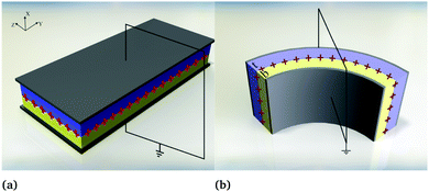 |
| | Fig. 19 A composite block made of two layers with two different dielectric materials and a layer of charge is inserted between two layers. (a) Undeformed configuration. (b) Deformed configuration. | |
Electric boundary conditions are identified as
where
r1,
rch and
r2 are the inner radius, interface radius and outer radius of the deformed structure, respectively. The voltage
Vi is the unknown electric potential at the interface of two materials and is created due to insertion of the charge layer. Charge distribution is exactly same as
eqn (54). So, using Maxwell's equations, voltage
Vi can be determined from following equation:
| |  | (E.4) |
Consequently, the electric field in the layers may be determined to be:
| | 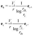 | (E.5) |
Since purely circular bending is considered, the mechanical boundary conditions for the model are as follows:
| | | rb = rt at r = rch, | (E.6b) |
| |  | (E.6c) |
| |  | (E.6d) |
| | | 〚tr〛 = 0 at r = rch, | (E.6e) |
| |  | (E.6f) |
Lagrange multipliers ![[script L]](https://www.rsc.org/images/entities/char_e144.gif) ab and
ab and ![[script L]](https://www.rsc.org/images/entities/char_e144.gif) at can be determined solving equilibrium equation for each layer and using boundary conditions (E.6c) and (E.6d):
at can be determined solving equilibrium equation for each layer and using boundary conditions (E.6c) and (E.6d):
| | 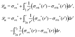 | (E.7) |
From eqn (E.6a), we conclude that Ab = At = A. Similar to eqn (45), A, Bb and Bt can be expressed in terms of r1, r2 and rch and using continuity of deformation (eqn (E.6b)) at the interface between two materials, r = rch, deformation can be expressed in terms of the two independent constants:
| |  | (E.8) |
where

. Finally,
eqn (E.6e) can be used to determine stretch
λb in terms of radius ratio
Λ| |  | (E.9) |
where coefficients
Eij are listed in the Appendix A. Also,
eqn (E.6f) can be written in terms of radius ratio and stretch:
| | 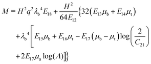 | (E.10) |
We can simply substitute
eqn (E.9) into
(E.10) to obtain a relation between the radius ratio and bending moment. Also, in order to extract a linear relation similar to
(59), the resulting relation can be linearized for small values of
![[small kappa, Greek, macron]](https://www.rsc.org/images/entities/i_char_e0cb.gif)
using Taylor series expansion and
eqn (51). Since the linearized relation is rather long, we avoid presenting it here and just present the following limiting case:
| |  | (E.11) |
Earlier we had emphasized that for an electret made of a single material, a non-zero curvature is observed in the block even in the absence of mechanical loading unless the charge layer is located exactly in the middle of the block. However,
eqn (E.11) shows that a non-zero bending moment is required to maintain a flat block even if the charge layer is located in the middle. In the other words, for a composite electret, and in absence of mechanical loading, a non-zero curvature can be observed in the block even if the charge layer is located in the middle of the block. The reason is that the material in-homogeneity intensifies non-uniformity of the Maxwell stress inside the material and this non-uniform distribution of stress bends the block.
As before for a single homogeneous electret material, the definitions (71) and (68) may be used to determine the apparent flexoelectric coefficient of the composite block:
| |  | (E.12) |
where
ε in relation
(71) has been replaced with
ε′ and is defined as
| |  | (E.13) |
In contrast to a homogeneous electret, we now note that the optimal position for the charge layer is not in the center of the structure and there is an optimum thickness for each layer which maximizes the apparent flexoelectric coefficient.
Acknowledgements
P. S. would like to gratefully acknowledge support from the M. D. Anderson Professorship and NSF CMMI grant 1463205.
References
- G. Buchberger, R. Schwödiauer and S. Bauer, Appl. Phys. Lett., 2008, 92, 123511 CrossRef.
-
F. Carpi, D. De Rossi, R. Kornbluh, R. E. Pelrine and P. Sommer-Larsen, Dielectric elastomers as electromechanical transducers: fundamentals, materials, devices, models and applications of an emerging electroactive polymer technology, Elsevier, 2011 Search PubMed.
- D. Yang, M. S. Verma, J.-H. So, B. Mosadegh, C. Keplinger, B. Lee, F. Khashai, E. Lossner, Z. Suo and G. M. Whitesides, Adv. Mater. Technol., 2016, 1 Search PubMed.
- C. Dagdeviren, B. D. Yang, Y. Su, P. L. Tran, P. Joe, E. Anderson, J. Xia, V. Doraiswamy, B. Dehdashti and X. Feng,
et al.
, Proc. Natl. Acad. Sci. U. S. A., 2014, 111, 1927–1932 CrossRef CAS PubMed.
- S. Bauer, S. Bauer-Gogonea, I. Graz, M. Kaltenbrunner, C. Keplinger and R. Schwödiauer, Adv. Mater., 2014, 26, 149–162 CrossRef CAS PubMed.
- J. Huang, S. Shian, Z. Suo and D. R. Clarke, Adv. Funct. Mater., 2013, 23, 5056–5061 CrossRef CAS.
- S. Yang, X. Zhao and P. Sharma, Soft Matter, 2017, 13, 4552–4558 RSC.
- T. Kelly, B. M. Ghadi, S. Berg and H. Ardebili, Sci. Rep., 2016, 6, 20128 CrossRef CAS PubMed.
- F. Carpi, S. Bauer and D. De Rossi, Science, 2010, 330, 1759–1761 CrossRef CAS PubMed.
- J. A. Rogers, T. Someya and Y. Huang, Science, 2010, 327, 1603–1607 CrossRef CAS PubMed.
- P. Muralt, R. Polcawich and S. Trolier-McKinstry, MRS Bull., 2009, 34, 658–664 CrossRef CAS.
- S. Trolier-McKinstry and P. Muralt, J. Electroceram., 2004, 12, 7–17 CrossRef CAS.
- S. B. Long, E. B. Campbell and R. MacKinnon, Science, 2005, 309, 903–908 CrossRef CAS PubMed.
- N. Murayama, K. Nakamura, H. Obara and M. Segawa, Ultrasonics, 1976, 14, 15–24 CrossRef CAS.
- C. Keplinger, T. Li, R. Baumgartner, Z. Suo and S. Bauer, Soft Matter, 2012, 8, 285–288 RSC.
-
L. Tian, PhD thesis, California Institute of Technology, Pasadena, CA, 2007.
- L. Tian, L. Tevet-Deree and K. Bhattacharya,
et al.
, J. Mech. Phys. Solids, 2012, 60, 181–198 CrossRef CAS.
- X. Zhao and Z. Suo, J. Appl. Phys., 2008, 104, 123530 CrossRef.
- S. J. A. Koh, T. Li, J. Zhou, X. Zhao, W. Hong, J. Zhu and Z. Suo, J. Polym. Sci., Part B: Polym. Phys., 2011, 49, 504–515 CrossRef CAS.
- S. J. A. Koh, X. Zhao and Z. Suo, Appl. Phys. Lett., 2009, 94, 262902 CrossRef.
- S. Bauer, R. Gerhard-Multhaupt and G. M. Sessler, Phys. Today, 2004, 57, 37–43 CrossRef CAS.
- G. Neugschwandtner, R. Schwödiauer, M. Vieytes, S. Bauer-Gogonea, S. Bauer, J. Hillenbrand, R. Kressmann, G. Sessler, M. Paajanen and J. Lekkala, Appl. Phys. Lett., 2000, 77, 3827–3829 CrossRef CAS.
- G. Neugschwandtner, R. Schwödiauer, S. Bauer-Gogonea and S. Bauer, Appl. Phys. A: Mater. Sci. Process., 2000, 70, 1–4 CrossRef CAS.
- J. Hillenbrand and G. Sessler, J. Appl. Phys., 2008, 103, 074103 CrossRef.
- S. Orrego, K. Shoele, A. Ruas, K. Doran, B. Caggiano, R. Mittal and S. H. Kang, Appl. Energy, 2017, 194, 212–222 CrossRef.
- C.-h. Yun, B. Watson, J. Friend and L. Yeo, IEEE Trans. Ultrason. Eng., 2010, 57, 1868–1874 Search PubMed.
- J. G. Smits, Sens. Actuators, A, 1990, 21, 203–206 CrossRef.
- S. A. Rios, A. J. Fleming and Y. K. Yong, IEEE Robot. Autom. Lett., 2017, 2, 337–343 Search PubMed.
- J. H. Yoo, J. I. Hong and W. Cao, Sens. Actuators, A, 2000, 79, 8–12 CrossRef CAS.
- S. Roundy and P. K. Wright, Smart Mater. Struct., 2004, 13, 1131 CrossRef.
-
M. J. Ramsay and W. W. Clark, SPIE's 8th Annual International Symposium on Smart Structures and Materials, 2001, pp. 429–438 Search PubMed.
- L. He, J. Lou, J. Du and J. Wang, Int. J. Mech. Sci., 2017, 122, 120–128 CrossRef.
- G. S. Neugschwandtner, R. Schwödiauer, S. Bauer-Gogonea, S. Bauer, M. Paajanen and J. Lekkala, J. Appl. Phys., 2001, 89, 4503–4511 CrossRef CAS.
- X. Zhang, P. Pondrom, L. Wu and G. Sessler, Appl. Phys. Lett., 2016, 108, 193903 CrossRef.
- S.-B. Choi and G.-W. Kim, J. Phys. D: Appl. Phys., 2017, 50, 075502 CrossRef.
- S. Baskaran, N. Ramachandran, X. He, S. Thiruvannamalai, H. J. Lee, H. Heo, Q. Chen and J. Y. Fu, Phys. Lett. A, 2011, 375, 2082–2084 CrossRef CAS.
- W. Ma and L. E. Cross, Appl. Phys. Lett., 2006, 88, 232902 CrossRef.
- J. Y. Fu, W. Zhu, N. Li and L. E. Cross, J. Appl. Phys., 2006, 100, 024112 CrossRef.
- A. G. Petrov, Anal. Chim. Acta, 2006, 568, 70–83 CrossRef CAS.
- A. Todorov, A. Petrov and J. Fendler, J. Phys. Chem., 1994, 98, 3076–3079 CrossRef CAS.
- F. Ahmadpoor and P. Sharma, Nanoscale, 2015, 7, 16555–16570 RSC.
- S. Krichen and P. Sharma, J. Appl. Mech., 2016, 83, 030801 CrossRef.
- P. Yudin and A. Tagantsev, Nanotechnology, 2013, 24, 432001 CrossRef CAS PubMed.
- P. Zubko, G. Catalan and A. K. Tagantsev, Annu. Rev. Mater. Res., 2013, 43, 387–421 CrossRef CAS.
- D. Lee and T. W. Noh, Philos. Trans. R. Soc., A, 2012, 370, 4944–4957 CrossRef CAS PubMed.
- T. D. Nguyen, S. Mao, Y.-W. Yeh, P. K. Purohit and M. C. McAlpine, Adv. Mater., 2013, 25, 946–974 CrossRef CAS PubMed.
- T. Q. Thai, T. Rabczuk and X. Zhuang, Comput. Methods Appl. Mech. Eng., 2018, 341, 718–739 CrossRef.
- H. Ghasemi, H. S. Park and T. Rabczuk, Comput. Methods Appl. Mech. Eng., 2018, 332, 47–62 CrossRef.
- R. A. Toupin, J. Math. Mech., 1956, 5, 849–915 Search PubMed.
-
A. C. Eringen and G. A. Maugin, Electrodynamics of continua, Springer Press, 1990, vol. I and II Search PubMed.
- A. Dorfmann and R. Ogden, Acta Mech., 2005, 174, 167–183 CrossRef.
- R. D. Mindlin, Int. J. Solids Struct., 1968, 4, 637–642 CrossRef.
- R. D. James and M. Wuttig, Philos. Mag. A, 1998, 77, 1273–1299 CAS.
- R. M. McMeeking and C. M. Landis, J. Appl. Mech., 2005, 72, 581–590 CrossRef.
- Z. Suo, X. Zhao and W. H. Greene, J. Mech. Phys. Solids, 2008, 56, 467–486 CrossRef CAS.
- Z. Suo, Acta Mech. Solida Sin., 2010, 23, 549–578 CrossRef.
- Y. Xiao and K. Bhattacharya, Arch. Ration. Mech. Anal., 2008, 189, 59–95 CrossRef.
- L. Liu, J. Mech. Phys. Solids, 2014, 63, 451–480 CrossRef.
- Q. Deng, L. Liu and P. Sharma, Phys. Rev. E: Stat., Nonlinear, Soft Matter Phys., 2014, 90, 012603 CrossRef.
- Q. Deng, L. Liu and P. Sharma, J. Mech. Phys. Solids, 2014, 62, 209–227 CrossRef CAS.
- L. Liu and P. Sharma, J. Mech. Phys. Solids, 2018, 112, 1–24 CrossRef.
- A. Mellinger, IEEE Trans. Dielectr. Electr. Insul., 2003, 10, 842–861 CrossRef CAS.
- A. Meitzler, H. Tiersten, A. Warner, D. Berlincourt, G. Couqin and F. Welsh III, IEEE Standard on Piezoelectricity, 1988 DOI:10.1109/IEEESTD.1988.79638.
- R. Rivlin, Proc. R. Soc. London, Ser. A, 1949, 463–473 CrossRef.
-
G. Sessler and R. Gerhard-Multhaupt, Electrets, Morgan Hill, 1999 Search PubMed.
- F. Ahmadpoor, Q. Deng, L. Liu and P. Sharma, Phys. Rev. E: Stat., Nonlinear, Soft Matter Phys., 2013, 88, 050701 CrossRef CAS PubMed.
- D. Berlincourt and H. Jaffe, Phys. Rev., 1958, 111, 143 CrossRef CAS.
- S. Qu and Y. Yu, J. Appl. Phys., 2011, 110, 043525 CrossRef.
- Q. Deng, M. Kammoun, A. Erturk and P. Sharma, Int. J. Solids Struct., 2014, 51, 3218–3225 CrossRef.
-
D. Bigoni, M. Gei and S. Roccabianca, Mathematical Methods and Models in Composites, World Scientific, 2014, pp. 173–207 Search PubMed.
Footnotes |
| † Electronic supplementary information (ESI) available. See DOI: 10.1039/c8sm01664j |
| ‡ – or other stimuli of interest such as magnetic fields, temperature among others. |
| § In this work we will not distinguish between the Maxwell stress effect and electrostriction since they are mathematically similar and this distinction does not impact the central message of our work. For further discussion on this topic, see ref. 16–18. |
| ¶ cf.ref. 19 and 20 for further details. Also, a somewhat deeper consideration will reveal that their approach for energy harvesting from dielectric elastomers can be considered as a special form of electrets where the charges reside on the surfaces. |
| || There are several equivalent ways to parametrize the piezoelectric property viz. as relation between the electric displacement and stress or polarization or strain; among others. In a widely used formalism, the electric displacement vector D is related to stress tensor σ through the third order piezoelectric tensor dijk (Di ∼ dijkσjk). Odd order tensors can only exist in non-centrosymmetric crystal structures and therefore piezoelectricity is restricted to only a limited set of materials. Furthermore, symmetry considerations for typical piezoelectric materials allows for only six independent components for the property tensor (out of the maximum possible 27). The electric displacement in the poling direction of material D3 can be correlated to three normal stresses σ11, σ22 and σ33 using contracted notation for piezoelectric coefficients: D3 ∼ d31σ11 + d32σ22 + d33σ33. The d33 (longitudinal) piezoelectric coefficient is important when both deformation (or stress) and polarization (or electric displacement) are in the poling direction (thickness direction in this paper) and d31 plays a pivotal role when the stress and electric displacement are in perpendicular direction with respect to each other. |
| ** There are several interesting uses of bending based energy generators from electromechanical coupling e.g. from the natural contractile and relaxation motions of the heart, lung, and diaphragm for self-powered wearable and implantable biomedical devices4 or to harvest wind energy by using a piezoelectric flag.25 Examples of sensors and actuators include micromotors,26 micropumps,27 robots28 and cooling fans.29 |
| †† There is an interesting and singular exception to the low d31 reports for electrets. Zhang et al.34 explored a rather special microstructure which did exhibit a notable d31 piezoelectric coefficient however a clear quantitative explanation was not presented. In due course, we will attempt to rationalize their results based on our developed models. |
‡‡ Flexoelectricity is characterized through the linear relation between polarization P and strain gradient ∇S mediated by a fourth order flexoelectric tensor f such that  . . |
§§ We emphasize that the domain of the second integral on the right hand side of eqn (5) is not reference configuration. We can write this term in the reference configuration as
|
| ¶¶ We remark that in the presently defined coordinate system, the longitudinal piezoelectric coefficient will be defined by examining the electric response in the X-direction in response to mechanical loading in the X-direction—as discussed in the theoretical models of Deng et al.59,60 |
|||| We remark that this constitutive relation is based on linearized theories of piezoelectricity which do not consider the incompressibility constraint. To connect our work as closely as possible to constitutive equations what experimentalists are likely to use, we employ (30) in this work.62,63| | | Di = εijEj + dijkΣjk, | (30) |
where Di, εij, Ej, dijk and Σjk are, respectively, components of the electric displacement, dielectric tensor, electric field, piezoelectric tensor and stress tensor. Using contracted notation and considering material symmetry d31 = d32, eqn (30) reduces to DX = d31(ΣYY + ΣZZ) in absence of external electric field and in presence of normal in-plane stresses. We can therefore determine the piezoelectric coefficient by measuring the change in the electric displacement in response to the applied loading. Analogously, in the case of the electret structure under consideration, we use the same notion to define an apparent piezoelectric coefficient. |
| *** We remark in passing that Deng et al.59,60 defined the apparent piezoelectric coefficient in a slightly different manner but to within a trivial scaling factor, the physics is identical. |
| ††† Most polymers and soft materials are nearly incompressible. However, foams are not. In the context of nonlinear elasticity and compressible materials, closed-form solutions are not possible for many of the boundary value problems considered in this work. To obtain analytical results, which provide transparent insights, we have made the assumption of incompressibility. In the ESI,† we have presented all-numerical calculations for the compressible case to verify that the approximate analytical results for incompressible materials are reasonable both qualitatively and quantitatively. |
| ‡‡‡ As typically understood in electrets, the charges and dipoles are immobile in the sense that they do not flow in the time scale (and temperature regime) of interest but do convect with deformation. Depending on the material properties, electret configuration and ambient temperature, discharge can occur on a time scale varying from days to decades.23,65 |
§§§ There are multiple ways to present constitutive equations for piezoelectricity. From (C.1), we can relate stress components σij to electric field components Ek and strain component Skl through the following relations
where ![[scr D, script letter D]](https://www.rsc.org/images/entities/char_e523.gif) km are the components of tensor km are the components of tensor  . Another alternative for the constitutive relation for piezoelectric materials may be expressed as . Another alternative for the constitutive relation for piezoelectric materials may be expressed as
| Sij = sEijklσkl + dkijEk, |
where sijkl and dkij are, respectively, components of compliance tensor and piezoelectric tensor and superscript E indicates that the quantity has been measured in constant or zero electric field. Introducing  such that such that  this constitutive relation can be rearranged as this constitutive relation can be rearranged as
Comparing this constitutive relation with the stress–strain relation presented based on the energy formulation and assuming cijkl − Bmij(![[scr D, script letter D]](https://www.rsc.org/images/entities/char_e523.gif) −1)mnBnkl ≈ cijkl, we arrive at the relation in (C.2) for a one-dimensional model. −1)mnBnkl ≈ cijkl, we arrive at the relation in (C.2) for a one-dimensional model. |
¶¶¶ In some of the literature, flexoelectric tensor μ is defined such that constitutive relation between polarization Pi, strain gradient  and electric field Ei is expressed as and electric field Ei is expressed as  where where ![[scr D, script letter D]](https://www.rsc.org/images/entities/char_e523.gif) ij is a component of ij is a component of  . However, we can also define the flexoelectric tensor f such that the internal energy density function is given by . However, we can also define the flexoelectric tensor f such that the internal energy density function is given by  . This internal energy density function will lead to the following equation: . This internal energy density function will lead to the following equation:  . So, we can conclude that . So, we can conclude that ![[scr D, script letter D]](https://www.rsc.org/images/entities/char_e523.gif) ijfjklm = −μijkl or in a one-dimensional setting, f(ε − ε0) = −μflexo. ijfjklm = −μijkl or in a one-dimensional setting, f(ε − ε0) = −μflexo. |
|
| This journal is © The Royal Society of Chemistry 2019 |
Click here to see how this site uses Cookies. View our privacy policy here.  *ac
*ac
![[Doublestruck R]](https://www.rsc.org/images/entities/char_e175.gif) 3 (which maps material points X from the reference configuration to the spatial points x in the current configuration Ω) and polarization
3 (which maps material points X from the reference configuration to the spatial points x in the current configuration Ω) and polarization ![[P with combining tilde]](https://www.rsc.org/images/entities/b_char_0050_0303.gif) : ΩR →
: ΩR → ![[Doublestruck R]](https://www.rsc.org/images/entities/char_e175.gif) 3. Deformation and polarization outside of the body are zero. Moreover, the gradient, divergence and curl operators in the current configuration are denoted by “grad”, “div” and “curl”, respectively. Gradient in the reference configuration is denoted by “∇”. The deformation gradient tensor is defined as F = ∇χ and the Jacobian is J = det
3. Deformation and polarization outside of the body are zero. Moreover, the gradient, divergence and curl operators in the current configuration are denoted by “grad”, “div” and “curl”, respectively. Gradient in the reference configuration is denoted by “∇”. The deformation gradient tensor is defined as F = ∇χ and the Jacobian is J = det![[thin space (1/6-em)]](https://www.rsc.org/images/entities/char_2009.gif) F.
F.![[thin space (1/6-em)]](https://www.rsc.org/images/entities/char_2009.gif) e = 0, div
e = 0, div![[thin space (1/6-em)]](https://www.rsc.org/images/entities/char_2009.gif) d = ρe, d = ε0e + p in V,
d = ρe, d = ε0e + p in V,![[Doublestruck R]](https://www.rsc.org/images/entities/char_e175.gif) , such that e = −grad
, such that e = −grad![[thin space (1/6-em)]](https://www.rsc.org/images/entities/char_2009.gif) ξ. Composition map can be used to denote e, d and p in the reference configuration
ξ. Composition map can be used to denote e, d and p in the reference configuration![[D with combining tilde]](https://www.rsc.org/images/entities/b_char_0044_0303.gif) , the nominal electric field Ẽ and the nominal polarization
, the nominal electric field Ẽ and the nominal polarization ![[P with combining tilde]](https://www.rsc.org/images/entities/b_char_0050_0303.gif) as
as![[D with combining tilde]](https://www.rsc.org/images/entities/b_char_0044_0303.gif) = JF−1D,
= JF−1D, ![[P with combining tilde]](https://www.rsc.org/images/entities/b_char_0050_0303.gif) = JP.
= JP.![[D with combining tilde]](https://www.rsc.org/images/entities/b_char_0044_0303.gif) =
= ![[small rho, Greek, tilde]](https://www.rsc.org/images/entities/i_char_e0e4.gif) e,
e, ![[D with combining tilde]](https://www.rsc.org/images/entities/b_char_0044_0303.gif) = −ε0JC−1∇ξ + F−1
= −ε0JC−1∇ξ + F−1![[P with combining tilde]](https://www.rsc.org/images/entities/b_char_0050_0303.gif) in VR,
in VR,![[small rho, Greek, tilde]](https://www.rsc.org/images/entities/i_char_e0e4.gif) e = Jρe∘χ for volume electric charge density and for surface charge density, J should be replaced with the surface Jacobian.
e = Jρe∘χ for volume electric charge density and for surface charge density, J should be replaced with the surface Jacobian.

![[Doublestruck R]](https://www.rsc.org/images/entities/char_e175.gif) 3 ×
3 × ![[Doublestruck R]](https://www.rsc.org/images/entities/char_e175.gif) 3×3 ×
3×3 × ![[Doublestruck R]](https://www.rsc.org/images/entities/char_e175.gif) 3 →
3 → ![[Doublestruck R]](https://www.rsc.org/images/entities/char_e175.gif) is the internal energy function of the body ΩR and nR is the unit normal to the boundary ∂VR. Also, ξb: ΓD →
is the internal energy function of the body ΩR and nR is the unit normal to the boundary ∂VR. Also, ξb: ΓD → ![[Doublestruck R]](https://www.rsc.org/images/entities/char_e175.gif) and
and ![[t with combining tilde]](https://www.rsc.org/images/entities/b_char_0074_0303.gif) e: ∂SN →
e: ∂SN → ![[Doublestruck R]](https://www.rsc.org/images/entities/char_e175.gif) 3 are the imposed boundary potential and traction (dead load), respectively, applied on the surfaces ΓD and SN (Fig. 3). In addition, as it is shown in Fig. 3, Dirichlet boundary condition χ = χb (χb: SD →
3 are the imposed boundary potential and traction (dead load), respectively, applied on the surfaces ΓD and SN (Fig. 3). In addition, as it is shown in Fig. 3, Dirichlet boundary condition χ = χb (χb: SD → ![[Doublestruck R]](https://www.rsc.org/images/entities/char_e175.gif) 3) and Robin boundary condition
3) and Robin boundary condition ![[D with combining tilde]](https://www.rsc.org/images/entities/b_char_0044_0303.gif) ·nR = Db (Db: ΓR →
·nR = Db (Db: ΓR → ![[Doublestruck R]](https://www.rsc.org/images/entities/char_e175.gif) ) are imposed on the surfaces SD and ΓR, respectively.
) are imposed on the surfaces SD and ΓR, respectively.
![[scr F, script letter F]](https://www.rsc.org/images/entities/char_e141.gif) [χ,
[χ,![[P with combining tilde]](https://www.rsc.org/images/entities/b_char_0050_0303.gif) ]: (χ,
]: (χ,![[P with combining tilde]](https://www.rsc.org/images/entities/b_char_0050_0303.gif) ) ∈
) ∈ ![[scr S, script letter S]](https://www.rsc.org/images/entities/char_e532.gif) and (χ,
and (χ,![[P with combining tilde]](https://www.rsc.org/images/entities/b_char_0050_0303.gif) ) satisfies (4)},
) satisfies (4)},![[scr S, script letter S]](https://www.rsc.org/images/entities/char_e532.gif) is the admissible set of functions over which the minimization is performed.
is the admissible set of functions over which the minimization is performed.
![[D with combining tilde]](https://www.rsc.org/images/entities/b_char_0044_0303.gif) ·nR = Db on ΓR, following system of governing equations and natural boundary condition should be solved simultaneously to determine the equilibrium state of the system:
·nR = Db on ΓR, following system of governing equations and natural boundary condition should be solved simultaneously to determine the equilibrium state of the system:
![[P with combining tilde]](https://www.rsc.org/images/entities/b_char_0050_0303.gif) ) =
) = ![[small rho, Greek, tilde]](https://www.rsc.org/images/entities/i_char_e0e4.gif) e in VR,
e in VR,


 is given as
 is the Piola–Maxwell stress


![[thin space (1/6-em)]](https://www.rsc.org/images/entities/char_2009.gif) d = ρe in Ω,
d = ρe in Ω,![[thin space (1/6-em)]](https://www.rsc.org/images/entities/char_2009.gif) σMW = 0 in V\Ω,
σMW = 0 in V\Ω,


![[Doublestruck R]](https://www.rsc.org/images/entities/char_e175.gif) 3: −H ≤ X ≤ αH, |Y| ≤ L, |Z| ≤ W},
3: −H ≤ X ≤ αH, |Y| ≤ L, |Z| ≤ W},![[Doublestruck R]](https://www.rsc.org/images/entities/char_e175.gif) 3: αH < X ≤ H, |Y| ≤ L, |Z| ≤ W},
3: αH < X ≤ H, |Y| ≤ L, |Z| ≤ W},
 . For the ease of notation, in what follows, we drop the subscript 1 and write λ1 = λ here and henceforth. In order to explore the implication of incompressibility constraint, we add one more term to the total free energy of the system given in eqn (5):
![[script L]](https://www.rsc.org/images/entities/char_e144.gif) a is a Lagrange multiplier. Also, ΩR may be replaced with ΩRt or ΩRb to derive the equilibrium equations for each of the layers. Due to this modification of free energy, eqn (9) and (13) are updated as
a is a Lagrange multiplier. Also, ΩR may be replaced with ΩRt or ΩRb to derive the equilibrium equations for each of the layers. Due to this modification of free energy, eqn (9) and (13) are updated as


![[t with combining tilde]](https://www.rsc.org/images/entities/b_char_0074_0303.gif) ei =
ei = ![[t with combining tilde]](https://www.rsc.org/images/entities/i_char_0074_0303.gif) eieY is the imposed traction (dead load) applied to each layer on the surfaces |Y| = L. As evident from the Maxwell's equations, the electric field is homogeneous within each layer. Therefore, eliminating
eieY is the imposed traction (dead load) applied to each layer on the surfaces |Y| = L. As evident from the Maxwell's equations, the electric field is homogeneous within each layer. Therefore, eliminating ![[script L]](https://www.rsc.org/images/entities/char_e144.gif) a from system of eqn (23), using boundary conditions (24), the equilibrium equation for each layer reduces to:
a from system of eqn (23), using boundary conditions (24), the equilibrium equation for each layer reduces to:


![[D with combining tilde]](https://www.rsc.org/images/entities/b_char_0044_0303.gif) = DteX. Substituting eqn (26) into eqn (22) we obtain:
= DteX. Substituting eqn (26) into eqn (22) we obtain:


![[t with combining tilde]](https://www.rsc.org/images/entities/b_char_0074_0303.gif) e=0 is the electric displacement in the absence of an externally applied loading. In what follows, for any parameter f, we define
e=0 is the electric displacement in the absence of an externally applied loading. In what follows, for any parameter f, we define  . As evident from eqn (29), in our considered electret structure (which is representative of conventionally fabricated electrets), Dft − Dit is zero. Therefore, the emergent dapp31 piezoelectric coefficient is also zero. This is to be contrasted with the derivation for the large dapp33 coefficient obtained for soft electrets.59 Physically, when a mechanical load in thickness direction is applied to the electret structure being considered, deformation distributes non-uniformly. This non-uniformity of deformation results in an appreciable value for the dapp33 piezoelectric coefficient. The material inhomogeneity is central to enable non-uniform deformation and the consequent non-zero dapp33 coefficient. This fact it is reflected in the expression***
![[thin space (1/6-em)]](https://www.rsc.org/images/entities/char_2009.gif) 59,60 for dapp33:
59,60 for dapp33:

![[Doublestruck R]](https://www.rsc.org/images/entities/char_e175.gif) 3: |X| ≤ H, |Y| ≤ L, |Z| ≤ W},
3: |X| ≤ H, |Y| ≤ L, |Z| ≤ W},


![[script L]](https://www.rsc.org/images/entities/char_e144.gif) aI.
aI.


![[script L]](https://www.rsc.org/images/entities/char_e144.gif) aI,
aI,


![[script L]](https://www.rsc.org/images/entities/char_e144.gif) aI)er = 0 at r = r1 and r = r2,
aI)er = 0 at r = r1 and r = r2,
![[script L]](https://www.rsc.org/images/entities/char_e144.gif) a can be determined to be
a can be determined to be


 as a representation for the curvature. Curvature
 ![[small kappa, Greek, macron]](https://www.rsc.org/images/entities/i_char_e0cb.gif) will be positive if r2 > r1 and vice versa. The ratio Λ in (48) can be easily related to curvature through relation:
will be positive if r2 > r1 and vice versa. The ratio Λ in (48) can be easily related to curvature through relation:![[small kappa, Greek, macron]](https://www.rsc.org/images/entities/i_char_e0cb.gif) .
.![[small kappa, Greek, macron]](https://www.rsc.org/images/entities/i_char_e0cb.gif) | ≪ 1. This condition is also valid for thick blocks under small deformations. It is therefore instructive to linearize (50) and (49) for the cases with |
| ≪ 1. This condition is also valid for thick blocks under small deformations. It is therefore instructive to linearize (50) and (49) for the cases with |![[small kappa, Greek, macron]](https://www.rsc.org/images/entities/i_char_e0cb.gif) | ≪ 1. Ignoring higher order terms, stretch and bending moment can then be expressed as
| ≪ 1. Ignoring higher order terms, stretch and bending moment can then be expressed as

![[small kappa, Greek, macron]](https://www.rsc.org/images/entities/i_char_e0cb.gif) and the external electric field is the only reason for the change of thickness.
and the external electric field is the only reason for the change of thickness.![[small kappa, Greek, macron]](https://www.rsc.org/images/entities/i_char_e0cb.gif) depends on the thickness of the block in the deformed configuration, and alteration in the external electric field will change the thickness and consequently curvature but ignoring the effect of external electric field on the thickness of the block will lead to the complete de-correlation of the curvature of the film and the external electric field.
depends on the thickness of the block in the deformed configuration, and alteration in the external electric field will change the thickness and consequently curvature but ignoring the effect of external electric field on the thickness of the block will lead to the complete de-correlation of the curvature of the film and the external electric field.![[small kappa, Greek, macron]](https://www.rsc.org/images/entities/i_char_e0cb.gif) is zero. This, in turn, signifies that no matter how large the applied electric field, flexure will not ensue in absence of an applied mechanical bending moment.
is zero. This, in turn, signifies that no matter how large the applied electric field, flexure will not ensue in absence of an applied mechanical bending moment.

![[script letter H]](https://www.rsc.org/images/entities/char_e142.gif) (·) is the Heaviside step function. We defer for now the discussion on the influence of external voltage and the actuator mode application of this structure. As done in prior sections, the stretch can be evaluated analytically in terms of the radius ratio Λ and other properties of the dielectric block:
(·) is the Heaviside step function. We defer for now the discussion on the influence of external voltage and the actuator mode application of this structure. As done in prior sections, the stretch can be evaluated analytically in terms of the radius ratio Λ and other properties of the dielectric block:
 . The coefficients Cij depend on Λ and α and their complete expressions are recorded in Appendix A. The bending moment necessary to maintain the desired deformation in terms of radius ratio using (46b) is
![[small kappa, Greek, macron]](https://www.rsc.org/images/entities/i_char_e0cb.gif) :
:![[small kappa, Greek, macron]](https://www.rsc.org/images/entities/i_char_e0cb.gif) + o(
+ o(![[small kappa, Greek, macron]](https://www.rsc.org/images/entities/i_char_e0cb.gif) ),
),


![[small kappa, Greek, macron]](https://www.rsc.org/images/entities/i_char_e0cb.gif) and
and ![[q with combining macron]](https://www.rsc.org/images/entities/i_char_0071_0304.gif) 0. The simple implication of this observation is that the coupling between the mechanical and electrical state of the dielectric block is significantly more intricate and stronger in electret structures as compared to ordinary dielectrics. Notably, any change in the amount of charge or the position of charge layer will change the bending moment required to cause a specific value of curvature even if we were to ignore changes in the thickness. This is in contrast to what we observed in eqn (53) for the small-deformation case of a thin homogeneous film under an external applied electric where the effect of the external voltage only emerges from a change in the thickness.
0. The simple implication of this observation is that the coupling between the mechanical and electrical state of the dielectric block is significantly more intricate and stronger in electret structures as compared to ordinary dielectrics. Notably, any change in the amount of charge or the position of charge layer will change the bending moment required to cause a specific value of curvature even if we were to ignore changes in the thickness. This is in contrast to what we observed in eqn (53) for the small-deformation case of a thin homogeneous film under an external applied electric where the effect of the external voltage only emerges from a change in the thickness.![[small kappa, Greek, macron]](https://www.rsc.org/images/entities/i_char_e0cb.gif) to derive an approximate linear relation for the curvature in terms of the bending moment
to derive an approximate linear relation for the curvature in terms of the bending moment

![[small kappa, Greek, macron]](https://www.rsc.org/images/entities/i_char_e0cb.gif) | ≪ 1 and derive an expression similar to (59) with modified values for D12 and M0. Relation for D12 is given in eqn (A.9). In order to provide insights into the bending behavior of electret under external voltage (in absence of any mechanical loading) we simply update the expression of M0 presented in eqn (61). The modified M0 may be derived to have the following form:
| ≪ 1 and derive an expression similar to (59) with modified values for D12 and M0. Relation for D12 is given in eqn (A.9). In order to provide insights into the bending behavior of electret under external voltage (in absence of any mechanical loading) we simply update the expression of M0 presented in eqn (61). The modified M0 may be derived to have the following form:
 . An intriguing implication from (64) is that in the presence of external electric field and absence of mechanical loading, a non-zero value for curvature is obtained—even for symmetric electrets (α = 0). Moreover, this curvature depends on the value of external electric field and any change of the external field will also alter the curvature. As will be discussed in the next section, this behavior may be interpreted as converse bending piezoelectric behavior.
![[D with combining tilde]](https://www.rsc.org/images/entities/b_char_0044_0303.gif) may be determined by using eqn (55), (39) and (3):
may be determined by using eqn (55), (39) and (3):
![[small kappa, Greek, macron]](https://www.rsc.org/images/entities/i_char_e0cb.gif) we can elucidate a linear relation between the change of electric displacement and curvature:
we can elucidate a linear relation between the change of electric displacement and curvature:


![[small kappa, Greek, macron]](https://www.rsc.org/images/entities/i_char_e0cb.gif) with 〈κ〉 in eqn (62) and extract the average curvature of the block and the electric displacement (66) in terms of bending moment. Then, substituting eqn (59) into eqn (69) we have:
with 〈κ〉 in eqn (62) and extract the average curvature of the block and the electric displacement (66) in terms of bending moment. Then, substituting eqn (59) into eqn (69) we have:


 where κb is given in (C.14). Substituting the value of the bending moment from (73), Wpiezo can be determined as


 and that increasing the amount of embedded charges or using softer materials can be used to increase ECR.


 and use this quantity throughout the section. Fig. 12b shows that for fixed non-zero values of bending moment, increasing external field results in the increase of the curvature observed in the block. However it is evident, from this figure, that if the applied bending moment is zero, electric field alone will not induce a change in curvature. In the other words, some pre-existing curvature should be present to observe a coupling between the curvature and electric field for ordinary dielectrics. This is one of limitations of dielectric actuators. Another one is that the electromechanical coupling in the non-electret soft dielectric block is generated from Maxwell stress effect which, by nature, is quadratic with respect to electric field. Accordingly, a change in the direction of the applied electric field will not alter the direction of the induced curvature.
![[q with combining macron]](https://www.rsc.org/images/entities/i_char_0071_0304.gif) 0 = 0.225 bends in response to external electric field and in absence of any external mechanical load. This value of electric charge will be attainable upon insertion of a layer of electric charge with q = 10−3 C m−2 into a PP film with μ = 0.95 MPa and ε = 2.35ε0.68 Furthermore, Fig. 14 shows that the direction of curvature depends on the direction of applied field. This linear relation is in contrast with the quadratic behavior of an ordinary dielectric under external voltage in the absence of external charges and proves the capability of soft electrets to be used as a bending actuator. The emergent d31 effect is stronger when the charge layer is in the middle of the block (α = 0).
0 = 0.225 bends in response to external electric field and in absence of any external mechanical load. This value of electric charge will be attainable upon insertion of a layer of electric charge with q = 10−3 C m−2 into a PP film with μ = 0.95 MPa and ε = 2.35ε0.68 Furthermore, Fig. 14 shows that the direction of curvature depends on the direction of applied field. This linear relation is in contrast with the quadratic behavior of an ordinary dielectric under external voltage in the absence of external charges and proves the capability of soft electrets to be used as a bending actuator. The emergent d31 effect is stronger when the charge layer is in the middle of the block (α = 0).


![[thin space (1/6-em)]](https://www.rsc.org/images/entities/char_2009.gif) 67 and q = 1 mC m−2. While a high longitudinal piezoelectric coefficient for electrets has been already reported, this is the first prediction for such a large d31 value.
67 and q = 1 mC m−2. While a high longitudinal piezoelectric coefficient for electrets has been already reported, this is the first prediction for such a large d31 value.


![[small kappa, Greek, macron]](https://www.rsc.org/images/entities/i_char_e0cb.gif) :
:


 where ε is the dielectric tensor and B is third order piezoelectric tensor. In a one-dimensional setting, ε and B can be replaced by ε33 and B31, respectively. Since the beam is composed of two layers of the same piezoelectric materials with opposite poling directions, we introduce piezoelectric coefficient b31 such that for B31 = b31 for z > 0 and B31 = −b31 for z ≤ 0. Also, we can relate B31 piezoelectric coefficient to commonly used d31 coefficient as§§§

 . Due to the piezoelectric effect and in response to deformation, polarization is developed inside the bimorph. We assume that the polarization and electric field are only developed in the thickness direction (p = pez and
  ). Accordingly the Maxwell equation (4) reduces to:

![[scr F, script letter F]](https://www.rsc.org/images/entities/char_e141.gif) [uz,p]:(uz,p) ∈
[uz,p]:(uz,p) ∈ ![[scr S, script letter S]](https://www.rsc.org/images/entities/char_e532.gif) and (uz,p) satisfies (C.4)},
and (uz,p) satisfies (C.4)},![[scr S, script letter S]](https://www.rsc.org/images/entities/char_e532.gif) is the admissible set of functions
is the admissible set of functions


 . Polarization can be determined in terms of displacement by substituting eqn (C.9) into eqn (C.4):


 and d represent the curvature of the Euler beam and induced charge at the electrodes, respectively. The piezoelectric coefficient of this bimorph can be obtained by measuring the electric displacement due to bending and by using relation (C.16). From eqn (C.16) and (C.2) we have
 where p = p(x)ez. The energy density function is given as:66,69
 where ε is electric permittivity for this homogeneous flexoelectric material. From eqn (D.1), the free energy of the system can be written as


![[script L]](https://www.rsc.org/images/entities/char_e144.gif) ab and
ab and ![[script L]](https://www.rsc.org/images/entities/char_e144.gif) at can be determined solving equilibrium equation for each layer and using boundary conditions (E.6c) and (E.6d):
at can be determined solving equilibrium equation for each layer and using boundary conditions (E.6c) and (E.6d):

 . Finally, eqn (E.6e) can be used to determine stretch λb in terms of radius ratio Λ

![[small kappa, Greek, macron]](https://www.rsc.org/images/entities/i_char_e0cb.gif) using Taylor series expansion and eqn (51). Since the linearized relation is rather long, we avoid presenting it here and just present the following limiting case:
using Taylor series expansion and eqn (51). Since the linearized relation is rather long, we avoid presenting it here and just present the following limiting case:


 .
.![[scr D, script letter D]](https://www.rsc.org/images/entities/char_e523.gif) km are the components of tensor
km are the components of tensor  . Another alternative for the constitutive relation for piezoelectric materials may be expressed as
 such that
  this constitutive relation can be rearranged as
![[scr D, script letter D]](https://www.rsc.org/images/entities/char_e523.gif) −1)mnBnkl ≈ cijkl, we arrive at the relation in (C.2) for a one-dimensional model.
−1)mnBnkl ≈ cijkl, we arrive at the relation in (C.2) for a one-dimensional model. and electric field Ei is expressed as
  where
where ![[scr D, script letter D]](https://www.rsc.org/images/entities/char_e523.gif) ij is a component of
ij is a component of  . However, we can also define the flexoelectric tensor f such that the internal energy density function is given by
  . This internal energy density function will lead to the following equation:
  . So, we can conclude that
 ![[scr D, script letter D]](https://www.rsc.org/images/entities/char_e523.gif) ijfjklm = −μijkl or in a one-dimensional setting, f(ε − ε0) = −μflexo.
ijfjklm = −μijkl or in a one-dimensional setting, f(ε − ε0) = −μflexo.


