Twist renormalization in molecular crystals driven by geometric frustration
Asaf
Haddad
a,
Hillel
Aharoni
 b,
Eran
Sharon
c,
Alexander G.
Shtukenberg
 d,
Bart
Kahr
 d and
Efi
Efrati
 *a
*a
aDepartment of Physics of Complex Systems, Weizmann Institute of Science, Rehovot 76100, Israel. E-mail: efi.efrati@weizmann.ac.il
bDepartment of Physics and Astronomy, University of Pennsylvania, Philadelphia, Pennsylvania 19104, USA
cRacah Institute of Physics, The Hebrew University of Jerusalem, Jerusalem 91904, Israel
dDepartment of Chemistry, New York University, New York, New York 10003, USA
First published on 10th December 2018
Abstract
Symmetry considerations preclude the possibility of twist or continuous helical symmetry in bulk crystalline structures. However, as has been shown nearly a century ago, twisted molecular crystals are ubiquitous and can be formed by about 1/4 of organic substances. Despite its ubiquity, this phenomenon has so far not been satisfactorily explained. In this work we study twisted molecular crystals as geometrically frustrated assemblies. We model the molecular constituents as uniaxially twisted cubes and examine their crystalline assembly. We exploit a renormalization group (RG) approach to follow the growth of the rod-like twisted crystals these constituents produce, inquiring in every step into the evolution of their morphology, response functions and residual energy. The gradual untwisting of the rod-like frustrated crystals predicted by the RG approach is verified experimentally using silicone rubber models of similar geometry. Our theory provides a mechanism for the conveyance of twist across length-scales observed experimentally and reconciles the apparent paradox of a twisted single crystal as a finite size effect.
1 Introduction
Nearly a century ago Ferdinand Bernauer made the extraordinary claim that more than 25% of organic molecular crystals can be crystallized into helical forms.1 Recently these results have been confirmed and elaborated using analytical techniques.2,3 Moreover, it was demonstrated that twist is observed also for single crystals that display no discernible density of defects.4 Our definition of a crystal is thus challenged, as the existence of twist inevitably breaks translation invariance, and therefore cannot be supported by any crystallographic structure. Despite the ubiquity of twisted crystals, the precise mechanism leading to their formation is not fully resolved yet.N-Benzoylglycine (hippuric acid, HA, shown in Fig. 1) is unique among twisted-crystal-forming componds in that it can form twisted morphologies crystallized from the melt, solution, or vapor phase. When grown by sublimation it crystallizes as thin rectangular rods with twist period (pitch) that increases with the rod thickness. The pitch ranges from a few microns to several hundred microns. Existing models aiming to explain the size dependent shape of HA rely on large concentrations of crystalline defects that cooperate in order to twist and deform an otherwise straight crystalline lattice.3 However, selected area electron diffraction images show sharp spots, SEM images demonstrate well defined facets and AFM images show clear uninterrupted atomic steps, all contributing to the observation that twisted HA is indeed a single crystal and showing no evidence of a high defect density.4 Moreover, quantitatively similar twisting behavior is observed when HA is crystalized from the melt5 or solution6 suggesting that the twisting is a result of material properties rather than due to specific crystallization dynamics.
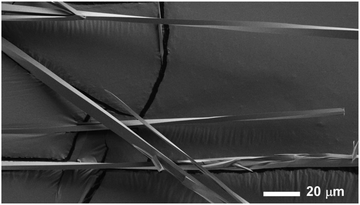 | ||
| Fig. 1 SEM image of N-benzoylglycine (hippuric acid, HA) crystals exhibiting size dependent pitch length. | ||
Size dependent behavior, such as that described above, is characteristic of geometrically frustrated assemblies.7 Geometrically frustrated systems are associated with two or more mutually contradicting geometric tendencies often giving rise to a local order that cannot be globally extended. Such system have no stress free configuration even in the absence of external constraints, and can be realized, mathematically or physically in many different ways.8–10 In the spirit of crystallization processes, a frustrated assembly could be formed by the ordered aggregation of incompatible units that must distort in order to fit next to one another in a periodic manner. This distortion in turn leads to residual stresses that may increase as the system grows and can gives rise to a variety of phenomena, such as defect creation,11 selection of high aspect ratio and filamentation,10,12,13 as well as growth arrest and size limitation.7,9,14
Intrinsic twist tendency of the constituents of an assembly is in general incompatible with long range order and thus leads to geometric frustration. This incompatibility takes different forms in different systems. In the liquid crystalline blue phase it arises from the geometric inability to sustain a biaxial twist of the director field in a three dimensional volume leading to gradual deviations from the biaxial twist and to finite width domains.15 A distinct type of frustration arises in twisted bundles of filaments that are allowed to slide past one another.16 In this case frustration arises from the inability to sustain constant filament spacing given the uniform twist. Here too the frustration may change the morphology of the bundle and lead to growth arrest.
In this work, inspired by the twisted molecular crystals of HA, we study the role geometric frustration assumes in the formation of twisted molecular crystals of macroscopic pitch lengths that continuously vary with crystal size. To achieve this we model the crystalline assembly of twisted deformable cubes. The crystalline order is enforced by prescribing the local topology of the constituents and in particular precluding their relative sliding. We observe that these constraints necessitate some deviations from the desired intrinsic geometric structure and that the degree of deviation depends on system size. As the crystalline assembly grows it gradually untwists, approaching an untwisted conformation in the limit of infinite size. We thus interpret the observed twist in molecular crystals as finite size effect and provide a mechanism for the size dependent conveyance of twist from the molecular to the macro-scale.
2 Results
We construct the model of twisted molecular crystals by assembling chiral continuous building blocks in a simple cubic lattice. The building blocks are cubes that possess a right handed twist along a single axis in their rest configuration, as depicted in Fig. 2A. We align the twist axis of all cubes along the z-direction, and identify adjacent faces of cubes to form a simply connected solid, i.e. the internal faces of the cubes are in full non-slip contact with their immediate neighbors. Physically, this assembly rule is supposed to model adjacent molecules that interact along multiple points such that both their relative positioning and relative orientations have a single preferred value, and deviations from this value increase the elastic energy. In particular, it precludes crystalline defects.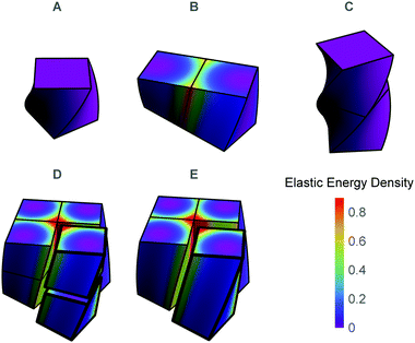 | ||
| Fig. 2 (A) The basic building block. (B) The lateral assembly of two cubes (2 × 1) necessitating some stress. (C) The longitudinal assembly of two cubes (1 × 2), requiring no stress. (D) 2 × 2 × 2 assembly of cubes. (E) 2 × 2 assembly of rods, which is equivalent to a 2 × 2 × 2 assembly of cubes. In D and E cubes and rods are separated from the main body for demonstration purposes. In all panels the color code corresponds to the elastic energy density obtained by minimizing the global elastic energy of the aggregate with respect to rod-like degrees of freedom of the constituents according to eqn (1). | ||
An assembly grows by the successive addition of new building blocks. Any new building block can connect either across the straight faces which are normal to the twist axis or transversely across the curved surfaces. These two possibilities are not energetically equivalent. As depicted Fig. 2B and C, connecting longitudinally across the twist direction incurs no mechanical cost, while connecting the curved surfaces necessitates some deformation and stress.
Assuming the mechanical energy landscape is convex (i.e. there are no local energy minima, at least not in the vicinity of the global minimum), implies that the conformation of the assembled object is independent of the order in which the constituents came together. Often geometric frustration may lead to non-convex elastic energies. However, for the case considered here, the simple geometry of the assembly and the proximity of the frustrated equilibrium to the unconstrained elastic equilibrium of the disconnected constituents suggest that the resulting elastic energy may indeed be convex. This is also verified experimentally by the robust stability of the unique equilibrium of the frustrated assembly.
We are thus free to recast the assembly in the most convenient form; we choose to consider each solid as composed of columns of cubes stacked along the twist axis and then connected to each other laterally. We term each of these columns the elementary twisted rod. The main advantage of this approach is that each of the elementary twisted rods is stress free before attaching to its neighbors and shares the same twist as the twisted cubes from which it is comprised. For example we can view the cubic eight blocks assembly, as an assembly of four rods each composed of two blocks stacked along their twist axis (see Fig. 2D and E). Following this approach we will model a solid of dimensions w × w × L as comprised of N2 twisted rods of square cross-section with side length w0, length L and preferred twist t0, such that w = Nw0.
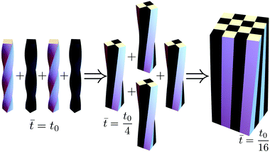
HA crystals grow as twisted rods that unwind as they grow thicker.4,5 Very thick rods unwind to the extent that their twist becomes indiscernible. Similarly, in our model one can show that the bulk assembly (obtained by taking the limit N = w/w0 → ∞) is morphologically trivial and displays no twist (see Appendix E). Thus to explore the origin of twist in molecular crystals one needs to consider them as assemblies of finitely many rods, rather than as a continua. This path to coarse graining is realized using a renormalization approach in which rods hierarchically assemble into thicker rods, as depicted in Fig. 3.
We model each of the elementary twisted rods mechanically as a Cosserat-rod, i.e. a rod that can twist about its mid-line, bend, stretch, shear its cross-section with respect to its mid-line and uniformly dilate its cross-section17–19 (see Appendix A for more details). Each of these deformation modes is associated with a preferred reference value, denoted with an over-bar and elastic moduli prescribing the energetic cost of deviating from these preferred values. The elastic energy, to leading order, may be brought to the form
 | (1) |
 . The entries in the coupling matrix G are the elastic moduli of the rod. We assume the length of rods is effectively infinite, and therefore we only consider deformations that are invariant along the rods’ long axes (i.e. we disregard finite length effects).
We start by assembling together four copies of the elementary twisted rod together to form a 2 × 2 aggregate where each of the rods is in full contact with it neighboring rods. The condition of full contact cannot be realized without some deviation from the reference parameters of the individual rods, i.e. cannot hold for all rods in the aggregate simultaneously. Finding the residually stressed configuration with least elastic energy gives the equilibrium configuration the 2 × 2 aggregate rod will adopt. The full contact condition and the symmetry of the aggregate require that the cross-section of the individual rods must remain normal to the z-axis, implying that the constituent rods wind around each other not by bending but rather by shearing. One can show that to leading order longitudinal stretching and cross-sectional dilations are not required, and that there is no linear coupling between shear and twist deformations, (see Appendix A). These lead to a simplified elastic energy per unit length of the aggregate that reads
 | (2) |
 | (3) |
 , which may differ from the physical width of the rod (noting again that for the isotropic and uniform case weff = w).
In the aggregate the full contact condition constrains the values the deformation may assume on the boundary connecting adjacent rods. Denoting the discontinuity of the rod's shear across the connecting face by Δv we obtain (see Appendix)
| |Δv1| = |Δv2| = w0u3. | (4) |
where α0 ≡ (w0/weff,0)2 and reads 1 for an isotropic and uniform rod.
Thus, in the absence of further external constraints, the aggregate will adopt the configuration of a twisted straight rod with twist t1. The resulting aggregate, provided that it still could be considered slender, may again be treated as a Cosserat rod. It is associated with the reference values  , and its new elastic moduli matrix G1 can be calculated directly from the response properties of its constituents.
This provides the basis for a renormalization group approach in which at every step four rods from generation n − 1 are joined to form the nth-generation rod of width wn = 2nw0. The first two such generations are illustrated in Fig. 3. Starting with the reference values for the elementary twisted rod  cited above we can show that all the reference values remain trivial except for the twist. Knowing the shear and twist moduli at every step we may repeat the minimization of the elastic energy (2) only replacing t0 by tn−1. The renormalization flow of the shear and twist moduli reads
 | (5) |
 , which converges to the physical width wn as n grows.
At every step the reference twist rescales according to
 | (6) |
Note that for an isotropic and uniform material (i.e. α0 = 1) we have for any step n
 .
.
A rod theory is derived by taking a series expansion in the system's width while assuming slenderness, i.e. assuming that the width is the smallest length scale in the system. In the present case of twisted rod assembly, the length of the rods is assumed to be infinite, and the only remaining length scale to compare the width to is the pitch (inversely related to the twist, t). Therefore a rod is slender if wt ≪ 1. When the width of the system is increased the assumption of slenderness may break and thus invalidate the use of rod theory. However, in the case considered here, whenever  then doubling the width results in increasing the pitch by more than two for all steps. Moreover, even if
  and wt will increase in a few initial steps, if the initial w0t0 is sufficiently small then the validity of the rod theory may hold. Therefore, the system becomes effectively more slender when it thickens, and the use of rod theory throughout is justified.
In each renormalization step the aggregate rod untwists further, and residual energy per rod,  , accumulates according to
Throughout the above treatment we assumed that the assembly forms a simply connected solid without cuts or holes. More specifically, if identical two dimensional coordinate grids were drawn on each of the faces of the rods, then the assembly rule implies that these coordinate grids must coincide on the common face between two adjacent rods. In general the direction of the third material coordinate (pointing away from the common surface) need not agree between adjacent rods. However, we observe that in the elastic equilibrium these directions also coincide. Framed more mathematically, our assembly rule requires only continuity of the embedding, yet at equilibrium we obtain also continuity of derivatives. Consequently, the configuration adopted by the aggregate rod coincides with the linear profiles of a uniform rod of similar cross-section despite the non-uniform profile of residual stresses in it. This motivates a top-down approach complementary to the renormalization approach employed above. In this top-down approach a large rod of cross-section A is decomposed to N × N rods of smaller cross sectional area A0 but with similar aspect ratio. This top-down approach allows us to generalize the result obtained from the renormalization approach, namely that t ∼ t0A0/A to arbitrary N (not only 2n), and to non-square elementary rod cross-sections, and even extend to rectangular assemblies of square rods to account for anisotropy in the assembly of the aggregate. See Appendix D.
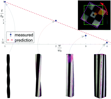
The model presented here aims to describe how molecular constituents come together to produce twisted crystals of pitch length measuring tens to hundreds of microns. However, as the main results appearing in eqn (5) and (6) are not scale dependent, we may test them using a table-top centimeter sized model. We cast silicone rubber elastic twisted rods and glue them to one another according to the full contact assembly rule described above (see Appendix F for methods used). Fig. 5 shows 1 × 1, 2 × 2, 3 × 3 and 4 × 4 aggregate rods, along with their measured twist, which are shown to agree well with their values predicted by eqn (6).
3 Discussion
We consider the problem of assembly of molecular constituents that possess some internal tendency to twist relative to one another. By reformulating the problem as the equivalent lateral assembly of square twisted rods we are able to follow the growth process and predict the gradual straightening of the twisted molecular crystal, as well as the increasing residual elastic energy associated with frustration in the assembly. This allows us to directly relate the moderate twist observed in macroscopic molecular crystals with the potentially nanometric pitch of the individual molecular building blocks, and to the elastic properties of the molecular assembly.It is natural to seek a continuum approach to the problem. Starting from a field theoretic approach one could write a theory that includes both elastic contributions, and liquid crystalline contributions (which include higher order spatial derivatives) that together reproduce the long wavelength behavior of the system.14 However, the origin of twist in this case is less transparent. Obtaining these field equations from first principles for molecular crystals is a challenge.
A step towards obtaining such a continuum theory from first principle is to identify the geometric charge associated with the frustrated assembly of twisted rods. However, the homogenization of the assembly presented here, obtained by considering a domain of constant size W × W × L composed of twisted square rods of dimensions w × w × L and of twist t0, and taking the limit w → 0 with the parameters W, L and t0 kept constant, results in a trivial Euclidean bulk with no residual elastic energy (see Appendix E for proof). Thus we cannot associate the frustration caused by a local twist with a simple Riemannian charge as one could do for the case of uniformly bent constituents20 or for incompatible surfaces.21
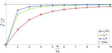
Geometrically frustrated systems often display a super-extensive elastic energy, i.e. that the energy per unit volume grows as the assembly becomes larger. For twisted rod aggregates we observe super extensive elastic energy for small aggregates (as observed in Fig. 4). However, for large assemblies the elastic energy per unit volume converges to a constant, rendering the elastic energy asymptotically extensive. Geometrically frustrated systems that possess a strongly super-extensive elastic energy exhibit a preference to form filamentous structures. In the present case, such a tendency may only exist in the early stages of the growth. Thus the filamentous profiles observed experimentally are likely not due to frustration alone but rather a signature of the early dynamics of the crystallization or of some other growth limiting factors.
Considering approximately isotropic rods in which w0 ∼ weff and α0 ∼ 1, the twist decays inversely proportional to the cross-sectional area of the aggregate from the very first renormalization step. However, if w0 ≪ weff then α0 ≪ 1 and the twist decays slower in the initial stages. As the aggregate grows, αn → 1 and the twist will again decay with the inverse of the cross-sectional area of the aggregate. As the molecular crystals observed in experiments are of micron size, orders of magnitude larger than the size of their molecular constituents they should be interpreted as large aggregates in which the value of αn is close to unity, and at every width doubling one expects the twist to diminish by a factor of four. It is important to note that in this late regime it is difficult to measure t0 and α0 separately. Naively extracting t0 while assuming αn = 1 for all n may lead to strong overestimation of the initial twist t0 for cases where α0 is small.
While the initial unwinding rate depends on the material parameter through α0, in all cases we considered, geometric frustration provides an effective means for conveying twist from the molecular scale to the scale of the aggregate. This results in size dependent pitch unwinding the crystal as it grows, and reconciles the simultaneous appearance of continuous twist and crystalline order as a finite size effect. Translational symmetry may not lead to the optimal arrangement of constituents for small crystals, but rather arise as an imperfect compromise in view of stringent geometric constraints as the crystal grows in size.
Conflicts of interest
There are no conflicts to declare.Appendices
A Cosserat rod energy for the isotropic case
A Cosserat rod consists of a parametrized curve![[r with combining right harpoon above (vector)]](https://www.rsc.org/images/entities/b_i_char_0072_20d1.gif) (s) and a moving Lagrangian orthonormal material frame of vectors
(s) and a moving Lagrangian orthonormal material frame of vectors ![[d with combining circumflex]](https://www.rsc.org/images/entities/b_i_char_0064_0302.gif) 1(s),
1(s), ![[d with combining circumflex]](https://www.rsc.org/images/entities/b_i_char_0064_0302.gif) 2(s),
2(s), ![[d with combining circumflex]](https://www.rsc.org/images/entities/b_i_char_0064_0302.gif) 3(s), such that the three dimensional embedding of the rod is given by
3(s), such that the three dimensional embedding of the rod is given by![[R with combining right harpoon above (vector)]](https://www.rsc.org/images/entities/b_i_char_0052_20d1.gif) (s,x,y) = (s,x,y) = ![[r with combining right harpoon above (vector)]](https://www.rsc.org/images/entities/b_i_char_0072_20d1.gif) (s) + σ(x (s) + σ(x![[d with combining circumflex]](https://www.rsc.org/images/entities/b_i_char_0064_0302.gif) 1(s) + y 1(s) + y![[d with combining circumflex]](https://www.rsc.org/images/entities/b_i_char_0064_0302.gif) 2(s)). 2(s)). | (7) |
Here (x,y) are the Lagrangian cross-section coordinates, not be confused with the absolute directions in space, and σ is the isotropic cross-sectional dilation. The evolution of the frame vectors with respect to the curve parameter s is given by the set of ODE's (using the Einstein summation rule over three Euclidean coordinates indexed by i, j, k):
∂s![[d with combining circumflex]](https://www.rsc.org/images/entities/b_i_char_0064_0302.gif) i = −εijkuj i = −εijkuj![[d with combining circumflex]](https://www.rsc.org/images/entities/b_i_char_0064_0302.gif) k, k, | (8) |
![[u with combining right harpoon above (vector)]](https://www.rsc.org/images/entities/b_i_char_0075_20d1.gif) = {u1, u2, u3}. The elements uj of the Darboux vector can in general be functions of s. Considering long rods we will limit our theory to only constant Darboux entries. The curve
= {u1, u2, u3}. The elements uj of the Darboux vector can in general be functions of s. Considering long rods we will limit our theory to only constant Darboux entries. The curve ![[r with combining right harpoon above (vector)]](https://www.rsc.org/images/entities/b_i_char_0072_20d1.gif) (s) is defined by the projections vi of its tangent on the frame vectors:
(s) is defined by the projections vi of its tangent on the frame vectors:∂s![[r with combining right harpoon above (vector)]](https://www.rsc.org/images/entities/b_i_char_0072_20d1.gif) (s) = vi (s) = vi![[d with combining circumflex]](https://www.rsc.org/images/entities/b_i_char_0064_0302.gif) i, i, | (9) |
 then s is the arc length parameter for the curve
 ![[r with combining right harpoon above (vector)]](https://www.rsc.org/images/entities/b_i_char_0072_20d1.gif) (s).
(s).
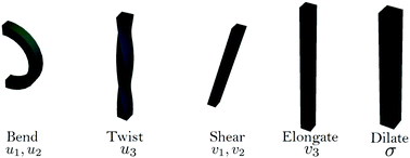
The elements ui and vi have clear geometrical interpretations; u1 and u2 correspond to bending while u3 corresponds to twisting. v1 and v2 measure shearing of the cross section with respect to the tangent curve, while v3 accounts for elongation in the direction normal to the cross section, (see Fig. 6).
We proceed to derive the energy of a Cosserat rod. The energy is a function of the strain, which is proportional to the difference between the metric of the rod's current configuration and its reference configuration metric. We use an overbar, –, to mark the parameters of the reference configuration. The reference dilation is set to 1 (without loss of generality).
We calculate the metric tensors gij, ḡij using (7):
 | (10) |
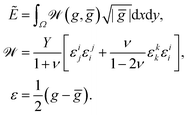 | (11) |
 , thus defining w as the (Lagrangian) width of the cross section.
We assume that the rods’ reference state is close to that of a straight simple rod (with vanishing shear, bend, twist and stretch), and that strains are small, implying that the parameters σ, ui and vj are close to their reference values. We do not restrict the relative magnitude of the different strain components, and simply expand to second order in the deviations from trivial geometry and in the strains.
We then take a 2nd order Taylor expansion of the energy in all of the reference variables, and assign a scaling exponent to each of the reference variables (e.g. ), and retain the lowest significant orders.
The second assumption is that of small strains. To do this we expand up to second order the configuration variables about the references (e.g. we expand u3 about ū3). We assign to each strain variable (i.e. terms like u3–ū3) a different scaling exponent, and any remaining reference configuration variables are assigned the same scaling exponents as in the first assumption. We retain only the lowest significant orders in each of the independent scaling exponents and derive the energy of a single rod:
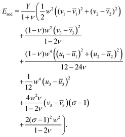 | (12) |
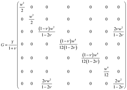
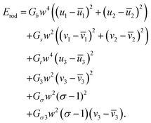
 as in eqn (1), with the elastic moduli matrix G given by:
Furthermore, as shown in Appendix D, in an aggregate rod with an elementary unit that has only non-zero reference twist (i.e. ū3 ≠ 0, ū1 = ū2 = 0), the only degrees of freedom (d.o.f) that evolve with system size or composition are the shear and the twist. We can therefore use a simplified energy, as used in the main body (2):
 | (13) |
B Full contact conditions on adjacent rods
In this section we express the ‘full contact’ assembly rule through constraints on the parameters that adjacent rods may assume. We consider a pair of adjacent rods of width w, and find the constraints by requiring continuity of the embeddings of the two rods on their common boundary (that the parametric curves from both rods coincide).We first consider an x border, i.e. a left–right border, corresponding to the coordinate value  for the left rod, and to
  for the right rod. The continuity condition is then:
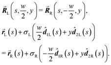 | (14) |
σL![[d with combining circumflex]](https://www.rsc.org/images/entities/b_i_char_0064_0302.gif) 2L(s) = σR 2L(s) = σR![[d with combining circumflex]](https://www.rsc.org/images/entities/b_i_char_0064_0302.gif) 2R(s). 2R(s). |
![[d with combining circumflex]](https://www.rsc.org/images/entities/b_i_char_0064_0302.gif) i frame vectors are of unit length, we must have that σL = σR ≡ σ. We are thus left with
i frame vectors are of unit length, we must have that σL = σR ≡ σ. We are thus left with![[d with combining circumflex]](https://www.rsc.org/images/entities/b_i_char_0064_0302.gif) 2L(s,u1L,u2L,u3L) = 2L(s,u1L,u2L,u3L) = ![[d with combining circumflex]](https://www.rsc.org/images/entities/b_i_char_0064_0302.gif) 2R(s,u1R,u2R,u3R). 2R(s,u1R,u2R,u3R). |
![[d with combining circumflex]](https://www.rsc.org/images/entities/b_i_char_0064_0302.gif) 2 frame vector is shared by two adjacent rods. The two remaining frame vectors
2 frame vector is shared by two adjacent rods. The two remaining frame vectors ![[d with combining circumflex]](https://www.rsc.org/images/entities/b_i_char_0064_0302.gif) 1 and
1 and ![[d with combining circumflex]](https://www.rsc.org/images/entities/b_i_char_0064_0302.gif) 3 have, in principle, a degree of freedom of a constant angle of rotation θ about the shared
3 have, in principle, a degree of freedom of a constant angle of rotation θ about the shared ![[d with combining circumflex]](https://www.rsc.org/images/entities/b_i_char_0064_0302.gif) 2, such that
2, such that ![[d with combining circumflex]](https://www.rsc.org/images/entities/b_i_char_0064_0302.gif) 1L·
1L·![[d with combining circumflex]](https://www.rsc.org/images/entities/b_i_char_0064_0302.gif) 1R ≡ cos(θ). In the following passages we will show that when two rods with shear and bend free reference configurations are joined in full contact, the equilibrium configuration has θ = 0, such that all the frame vectors between the two rods are shared. We examine the first derivative of
1R ≡ cos(θ). In the following passages we will show that when two rods with shear and bend free reference configurations are joined in full contact, the equilibrium configuration has θ = 0, such that all the frame vectors between the two rods are shared. We examine the first derivative of ![[d with combining circumflex]](https://www.rsc.org/images/entities/b_i_char_0064_0302.gif) 2 in the left and right rods:
2 in the left and right rods: | (15) |
![[d with combining circumflex]](https://www.rsc.org/images/entities/b_i_char_0064_0302.gif) 1L and
1L and ![[d with combining circumflex]](https://www.rsc.org/images/entities/b_i_char_0064_0302.gif) 3L, respectively we obtain:
3L, respectively we obtain: | (16) |
![[d with combining circumflex]](https://www.rsc.org/images/entities/b_i_char_0064_0302.gif) 2, and examining the part perpendicular to
2, and examining the part perpendicular to ![[d with combining circumflex]](https://www.rsc.org/images/entities/b_i_char_0064_0302.gif) 2, we obtain:
2, we obtain:u3Lu2L![[d with combining circumflex]](https://www.rsc.org/images/entities/b_i_char_0064_0302.gif) 3L + u1Lu2L 3L + u1Lu2L![[d with combining circumflex]](https://www.rsc.org/images/entities/b_i_char_0064_0302.gif) 1L = u3Ru2R 1L = u3Ru2R![[d with combining circumflex]](https://www.rsc.org/images/entities/b_i_char_0064_0302.gif) 3R + u1Ru2R 3R + u1Ru2R![[d with combining circumflex]](https://www.rsc.org/images/entities/b_i_char_0064_0302.gif) 1R. 1R. | (17) |
![[d with combining circumflex]](https://www.rsc.org/images/entities/b_i_char_0064_0302.gif) 1L we find
1L we find | (18) |
 | (19) |
![[d with combining circumflex]](https://www.rsc.org/images/entities/b_i_char_0064_0302.gif) 2,
2, ![[d with combining circumflex]](https://www.rsc.org/images/entities/b_i_char_0064_0302.gif) 1L and
1L and ![[d with combining circumflex]](https://www.rsc.org/images/entities/b_i_char_0064_0302.gif) 3L respectively, we obtain:
3L respectively, we obtain: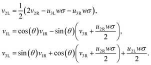 | (20) |
 | (21) |
![[v with combining macron]](https://www.rsc.org/images/entities/i_char_0076_0304.gif) 1 =
1 = ![[v with combining macron]](https://www.rsc.org/images/entities/i_char_0076_0304.gif) 2 = 0, ū1 = ū2 = 0 and
2 = 0, ū1 = ū2 = 0 and ![[v with combining macron]](https://www.rsc.org/images/entities/i_char_0076_0304.gif) 3 = 1 to account for rods that have a shear and bend free reference configuration. We express the combined energy of both rods in terms of the parameters of the right rod, using (16), (18) and (20). However, due to some non-linear couplings in (16) and (20), the combined resulting energy of the two rods has terms of higher order than the original quadratic form of each of the single rods. Retaining terms up to second order in all variables, we attempt to find local minima in the energy landscape by equating the gradient of the combined energy to zero. For the ∂uiR and ∂viR terms in the gradient, an exact solution exists in terms of θ and σ. The ∂θ term can however only be solved numerically, and it can be shown that for a wide applicable range of system parameters the solution is θ = 0 (θ = π is also a solution but has higher global energy). After setting θ = 0 an exact solution for the ∂σ term is also obtained.
3 = 1 to account for rods that have a shear and bend free reference configuration. We express the combined energy of both rods in terms of the parameters of the right rod, using (16), (18) and (20). However, due to some non-linear couplings in (16) and (20), the combined resulting energy of the two rods has terms of higher order than the original quadratic form of each of the single rods. Retaining terms up to second order in all variables, we attempt to find local minima in the energy landscape by equating the gradient of the combined energy to zero. For the ∂uiR and ∂viR terms in the gradient, an exact solution exists in terms of θ and σ. The ∂θ term can however only be solved numerically, and it can be shown that for a wide applicable range of system parameters the solution is θ = 0 (θ = π is also a solution but has higher global energy). After setting θ = 0 an exact solution for the ∂σ term is also obtained.
We have thus found that when the θ degree of freedom is available to an assembly of two rods, the minimal energy configuration has θ = 0. Assuming the energy landscape is convex about its minima, we set θ = 0 permanently for all further calculations. This implies that the frame vectors ![[d with combining circumflex]](https://www.rsc.org/images/entities/b_i_char_0064_0302.gif) i are shared and that all ui are also shared. Moreover the shear and elongation parameters along an x border are related by:
i are shared and that all ui are also shared. Moreover the shear and elongation parameters along an x border are related by:
 | (22) |
 | (23) |
C Adjacent rods in full contact can be described as a single rod
Two linear functions on adjacent domains that are continuous across the domains’ boundary will not necessarily form a linear function on the union of the domains. For example the function | (24) |
Within the Cosserat rod theory the deformations in the cross-section of the rod are assumed linear. Thus, when joining different Cosserat rods, one may in general obtain a deformation profile that is not linear in the cross-section of the union of the rods. In this appendix we show that while the full contact condition may seem to require only continuity of the embedding, it in fact enforces continuity of derivatives as well.
Using the result of Appendix B we can show that
∂x![[R with combining right harpoon above (vector)]](https://www.rsc.org/images/entities/b_i_char_0052_20d1.gif) L(s, x, y)|x=w/2 = L(s, x, y)|x=w/2 = ![[d with combining right harpoon above (vector)]](https://www.rsc.org/images/entities/b_i_char_0064_20d1.gif) 2 = ∂x 2 = ∂x![[R with combining right harpoon above (vector)]](https://www.rsc.org/images/entities/b_i_char_0052_20d1.gif) R(s, x, y)|x=−w/2. R(s, x, y)|x=−w/2. |
Thus each of the constituents in a rod aggregate share the bend, twist and dilation with those of the aggregate rod and inherit their shear and elongation from the rod aggregate by appropriately translating the mid-curve by a cross-sectional vector (α1,α2) ≡ ![[small alpha, Greek, vector]](https://www.rsc.org/images/entities/b_i_char_e118.gif) , and examining the behavior of the mid-curve's tangent vector.
, and examining the behavior of the mid-curve's tangent vector.
 | (25) |
 | (26) |
 .
.
D Top-down approach
Based on the finding that rods in a full-contact can be equivalently described as a single rod (see Appendix C), we provide an alternative method to calculate the full configuration of a rod aggregate (reference parameters, elastic moduli and residual energy) in a single step. Moreover, with this method we can generalize the description to rods of a general rectangular cross section, subdivided into any N × M square rods (compared to the 2N× 2N square rods assembly accessible through the renormalization).We consider an N × M rod assembly, of overall width W and thickness T. The width of the constituent square rods that make up the generally rectangular aggregate is  . Therefore, we can express
  . The displacement of each constituent rod mid-curve from the center of the aggregate rod is given by
 | (27) |
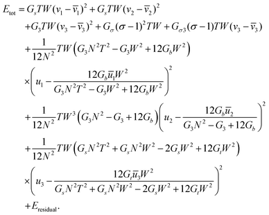
We use the energy functional from (21), for a rod of width w, which is a generalization of the isotropic energy (12) found in Appendix A. Note again that for ease of calculation we retain the dimensional part of the moduli; for example we write Gtw4 instead of simply noting the twist modulus Gt as we do in (2). We proceed to express the rod energy of each of the constituent rods as a function of the parameters of the aggregate rod. We do this by replacing the vi parameters in each rod according to (25), using the displacements  defined in (27). Additionally, we replace the width of each constituent rod
  , N being the number of times the aggregate is split across the width of the aggregate. Thus the energy of a single constituent rod is Erod[n,m], and the overall aggregate energy is the sum of all the constituent rods:
 | (28) |
 | (29) |
 | (30) |
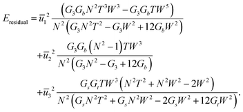
(29) had the same quadratic form as that of a single rod,  (as in (21) and (12)), and as such its minimizers (or new references) are found trivially. Note that only the reference bend and reference twist evolve non-trivially with N. For the particular case of vanishing reference bends of the constituent rods, we obtain that the rod assembly has only a non-trivial twist. This twist, however, contributes to both twist and shear of the constituent rods through (26), justifying the form of the simplified rod-energy (2).
Thus the top-down approach is an alternative and more general way to calculate the energy of a rod aggregate for any rectangular assembly. Setting  we recover the results of the bottom-up approach presented in the main text (recalling that N2 = 4n, where N is the number of top-down splits and n is the number of RG steps).
Taking N → ∞ while keeping W and T constant is akin to a homogenization procedure, whereby a fixed volume is subdivided into elementary rods with vanishing size. In this limit we find that the residual energy (30) vanishes, as do the twist and bend references. These results can be seen also as consequences of the triviality of the Riemannian limit of the system, discussed in the next appendix.
E Trivial homogenization
In this appendix we prove that the Riemannian homogenization of the twisted rod assembly is trivial. This is in contrast with other frustrated assembly processes where the homogenization is not trivial and its properties dominate the system's behavior. One of the simplest cases is that of an assembly of rods of constant radius of curvature, ρ and width δ connected to one another.22 The discontinuity in geodesic curvature across the curve connecting two adjacent stripes renders the metrics of the assembly at any finite δ non-differentiable. However, the limit of δ → 0 while keeping ρ constant results in a smooth geometry of constant Gaussian curvature K = −1/ρ2, as has been demonstrated in ref. 22 and can be inferred from the vanishing splay and constant bend compatibility condition for two dimensional liquid crystals.20Examining the case of twisted rod assembly leads us to consider joining N × N twisted straight rods of twist t and width w, such that the total width of the assembly's cross section is W = Nw. The homogenization of the rod assembly corresponds to the limit w → 0 while keeping W and t constant.
The metric of a single twisted straight rod with respect to the cross sectional Lagrangean coordinates x and y is given by
| ḡw(x,y) = ḡw(x + w,y) = ḡw(x,y + w). |
For simplicity we consider the case of a vanishing Poisson ratio for which, up to constants, the elastic energy of a metric g with respect to ḡw is given by
The inverse metric for a straight twisted rod reads
 . We set the limiting energy functional to read
Noting that ḡw = I +
![[scr O, script letter O]](https://www.rsc.org/images/entities/char_e52e.gif) (w) and ḡw−1 = I +
(w) and ḡw−1 = I + ![[scr O, script letter O]](https://www.rsc.org/images/entities/char_e52e.gif) (w) we obtain
(w) we obtainEw = E0 + ![[scr O, script letter O]](https://www.rsc.org/images/entities/char_e52e.gif) (w). (w). | (31) |
It remains to show that for every sequence of metrics gn → g and wn → 0 as n → ∞ we have
For every metric g such that E0 < ∞ it is straightforward to show that |Ew(g) − E0(g)|/w < C for all w, for some 0 < C that may depend on E0 but not on w. Therefore
 .
.Thus for bounded Euclidean metrics g
F Methods
The silicone rubber twisted rod assemblies were created by casting liquid silicone rubber (Smooth-On, Inc. Mold-Max™ NV14) in 3D printed molds (Formlabs, Inc, Form 2 printer, using Grey resin). The individual elementary rods were cast as twisted straight rods of pitch length of 16 cm and square cross-section of width 0.8 cm. White and grey pigmented cured rods were clamped into a straight conformation to align their faces and then were glued together using red-pigmented uncured resin (of the same material as the rod) resulting in continuous rod aggregates with no discernible variation in material properties. After curing, the aggregate rods were photographed from below in their unconstrained state. Image edges were detected via a Roberts cross operator (MATLAB ‘edge’ function) and the twist was inferred by identifying the feature orientation using a Radon transform.Acknowledgements
This work was supported by the National Science Foundation under Award DMR-1608374. It was supported partially by the Materials Research Science and Engineering Center (MRSEC) program of the National Science Foundation (NSF) under Award DMR-1420073. H. A. was supported by NSF grant no. DMR-1262047. E. E. is the incumbent of the Ernst and Kaethe Ascher career development chair and thanks the Ascher foundation for their support, and also acknowledges the support by the Alon fellowship. This work was funded by NSF/DMR-BSF grant 2015670, the Minerva foundation grant number 712273, and by the ISF grant number 1479/16.Notes and references
- F. Bernauer, Gedrillte Kristalle, Borntraeger, 1929 Search PubMed.
- A. Shtukenberg, E. Gunn, M. Gazzano, J. Freudenthal, E. Camp, R. Sours, E. Rosseeva and B. Kahr, ChemPhysChem, 2011, 12, 1558–1571 CrossRef CAS.
- A. G. Shtukenberg, Y. O. Punin, A. Gujral and B. Kahr, Angew. Chem., Int. Ed., 2014, 53, 672–699 CrossRef CAS.
- A. G. Shtukenberg, A. Gujral, E. Rosseeva, X. Cui and B. Kahr, CrystEngComm, 2015, 17, 8817–8824 RSC.
- A. G. Shtukenberg, J. Freudenthal and B. Kahr, J. Am. Chem. Soc., 2010, 132, 9341–9349 CrossRef CAS.
- P. Calvert and D. Uhlmann, J. Polym. Sci., Part B: Polym. Phys., 1973, 11, 457–465 CAS.
- G. M. Grason, J. Chem. Phys., 2016, 145, 110901 CrossRef.
- E. Efrati, E. Sharon and R. Kupferman, J. Mech. Phys. Solids, 2009, 57, 762–775 CrossRef.
- S. Armon, H. Aharoni, M. Moshe and E. Sharon, Soft Matter, 2014, 10, 2705–2908 RSC.
- G. Meng, J. Paulose, D. R. Nelson and V. N. Manoharan, Science, 2014, 343, 634–637 CrossRef CAS.
- W. T. M. Irvine, V. Vitelli and P. M. Chaikin, Nature, 2010, 468, 947–951 CrossRef CAS PubMed.
- E. Efrati, E. Sharon and R. Kupferman, Soft Matter, 2013, 9, 8187–8197 RSC.
- S. Schneider and G. Gompper, Europhys. Lett., 2005, 70, 136–142 CrossRef CAS.
- G. M. Grason, Phys. Rev. E: Stat., Nonlinear, Soft Matter Phys., 2009, 79, 041919 CrossRef.
- P. G. de Gennes and J. Prost, The physics of liquid crystals, Clarendon Press, 1993, p. 324 Search PubMed.
- D. M. Hall, I. R. Bruss, J. R. Barone and G. M. Grason, Nat. Mater., 2016, 15, 727–732 CrossRef CAS.
- E. Cosserat and F. Cosserat, Bull. Am. Math. Soc., 1913, 19, 242–246 CrossRef.
- N. Chouaieb and J. H. Maddocks, J. Elasticity, 2004, 77, 221–247 CrossRef.
- S. Antman, Nonlinear Problems of Elasticity, Springer, 2nd edn, 2005, p. 845 Search PubMed.
- I. Niv and E. Efrati, Soft Matter, 2018, 424–431 RSC.
- S. Armon, E. Efrati, R. Kupferman and E. Sharon, Science, 2011, 333, 1726–1730 CrossRef CAS.
- D. W. Henderson and D. Taimina, Math. Intell., 2001, 23, 17–28 CrossRef.
| This journal is © The Royal Society of Chemistry 2019 |

