Facile synthesis of self-supported amorphous phosphorus-doped Ni(OH)2 composite anodes for efficient water oxidation†
Gang
Yuan
 ab,
Yujie
Hu
a,
Zihan
Wang
a,
Qiwei
Wang
a,
Li
Wang
ab,
Xiangwen
Zhang
ab and
Qingfa
Wang
ab,
Yujie
Hu
a,
Zihan
Wang
a,
Qiwei
Wang
a,
Li
Wang
ab,
Xiangwen
Zhang
ab and
Qingfa
Wang
 *ab
*ab
aKey Laboratory for Green Chemical Technology of the Ministry of Education, School of Chemical Engineering and Technology, Tianjin University, 92 Weijin Road, Tianjin 300072, P. R. China. E-mail: qfwang@tju.edu.cn
bCollaborative Innovation Centre of Chemical Science and Engineering (Tianjin), Tianjin University, Tianjin 300072, P. R. China
First published on 27th November 2019
Abstract
Water oxidation plays a pivotal role in energy conversion and storage such as in water splitting and metal-air batteries. The development of a highly active and stable electrode for water oxidation at a low price is greatly challenging. Here, we report a self-supported oxygen evolution reaction (OER) electrode with a 3D porous Ni foam (NF) as a core and a dense layer of amorphous phosphorus-doped Ni hydroxide (Ni–OH/P) film as a shell. This facilely fabricated 3D core–shell structured electrode with directly grown active materials offered improved activity and prolonged stability for OER. It required an overpotential of 490 mV to deliver a current density of 100 mA cm−2; it showed a small Tafel slope at 87 mV dec−1 and sustained elongated electrolysis at 100 mA cm−2 for 100 h. The NiOOH shell was in situ formed on the surface of the Ni–OH/P film. Then, a new core–shell structured film was constructed. The synergetic effects of the newly formed crystalline NiOOH shell and amorphous Ni–OH/P core contributed to high stability under harsh conditions. This work presents a facile and easy scale-up path to develop self-supported hybrid electrodes for efficient and stable energy conversion and storage.
1. Introduction
The rapid growth of human activities, exhaustion of fossil fuels, and increase in CO2 emissions have driven researchers to search sustainable and clean energy. The solar, wind, and tide energies offer environmentally friendly sources for clean energy production. To convert these decentralized energies and water into storable hydrogen fuels, water oxidation (i.e., the oxygen evolution reaction, OER) plays a vital role. Nevertheless, OER suffers from sluggish kinetics and thus requires a high overpotential to deliver a discernible current. Noble metal oxides (e.g., IrO2 and RuO2) with high OER kinetics are still the state-of-the-art OER catalysts.1,2 However, the high cost, scarcity, and poor stability of these conventional OER catalysts have restrained their practical applications.3 Therefore, the design and facile fabrication of efficient and stable low-cost earth-abundant OER electrodes are highly essential to fulfill the demands of continual green energy supply.Recent advances have led to a large number of transition metal (TM)-based electrocatalysts, including TM borates,4 phosphates,5 phosphides,6 oxides,7 and hydroxides.8 Among these electrocatalysts, nickel-based materials have received substantial attention benefitting from their high electrical conductivity and OER activity.9 Until now, Ni-based (oxy)hydroxides (e.g., NiOx, Ni(OH)2, and NiOOH) are among the most active catalysts reported for alkaline OER.10,11 Nevertheless, the OER activity of these materials is still hindered by their low electrical conductivity and poor stability. To tackle these problems, efforts have been made to regulate the electronic structure by modifying composition,12 doping heteroatoms,13 building defects,14 and hybridizing conductive substrates.15 Recently, a highly conductive nickel foam (NF) has been widely accepted as a substrate for the synthesis of ready-to-use self-supported electrodes.16 With active materials grown directly on the substrate, the self-supported electrodes are superior to conventional power electrocatalysts.17 Numerous strategies have been explored for optimizing the NF-supported Ni(OH)2-based electrodes to enhance the reaction kinetics and stability. For example, Yuan et al. developed Fe-doped Ni(OH)2 on an NF composite anode with improved OER activity and stability than those of Ni(OH)2 and benchmark IrO2.18 Meanwhile, self-supported metal hydroxylphosphate has also been reported as an inexpensive and efficient OER anode.19,20 Some studies have also demonstrated that TM-based phosphate/phosphide electrocatalysts possess remarkable catalytic performances towards OER.21 Besides, it is reported that the short-range ordered amorphous materials are more active OER catalysts than their crystalline counterparts.22 The above-mentioned works inspired us to develop a self-supported amorphous phosphorus-doped Ni(OH)2 hybrid electrocatalyst for OER. However, it is technically difficult for the controllable combination of TM hydroxide and TM phosphorus because of the huge difference in their preparation environments.
In this study, we presented a facile low-temperature hydrothermal phosphidation method for controllably assembling a self-supported amorphous phosphorus-doped Ni(OH)2 (denoted as Ni–OH/P) anode. The optimized Ni–OH/P catalyst exhibited high activity and prolonged stability towards OER. It afforded a small overpotential of 490 mV at 100 mA cm−2, performed rapid OER kinetics with a small Tafel slope of 87 mV dec−1, which was slightly higher than that of RuO2 (80 mV dec−1), and continuously produced O2 at 100 mA cm−2 for at least 100 h with a negligible decline in catalytic activity. The characterization results confirmed that the Ni–OH/P film transformed into a new core–shell structured film with the in situ formed NiOOH as the shell. Its high activity and long stability originated from the synergetic effects between Ni–P and Ni(OH)2 and the protective nature of the NiOOH film, respectively.
2. Experimental
2.1 Chemicals
Nickel foam with 110 pores per inch and a mass density of 350 g m−2 was purchased from Jiashide (Soochow, China). Sodium hypophosphite (NaH2PO2), sodium acetate (CH3COONa), potassium hydroxide (KOH), nickel(II) acetate (Ni(CH3COO)2), and anhydrous ethanol are all at 99%, purchased from Aladdin Co., Ltd. and used without further purification. Oxygen at 99.9% was purchased from Liufang Co., Ltd. Ultrapure water with an electrical resistance of 18.2 MΩ cm−1 was homemade by a Millipore machine (Milli-Q Advantage A10 system).2.2 Synthesis of self-supported phosphorus-doped Ni(OH)2 on Ni foam
Ni foam-supported amorphous phosphorus-doped Ni(OH)2, referred to as Ni–OH/P, was prepared by a simple one-step hydrothermal phosphidation process. In a regular run, a slice of Ni foam was pretreated by ultrasonication in acetone, 6 M HCl, ethanol and ultrapure water successively for 5 minutes each.23–25 Then, it was immersed into a Teflon-lined stainless steel autoclave containing a 30 mL aqueous solution of 5 mM Ni(CH3COO)2, 5 mM CH3COONa, and 0.5 M NaH2PO2.26 Then, the autoclave was put in an electrical oven for the hydrothermal reaction at 180 °C for 4 h to obtain Ni–OH/P. Finally, the samples were rinsed with copious distilled water and then dried in an electric vacuum oven at 60 °C for 12 h after the autoclave was cooled down to room temperature. The reference RuO2 catalyst was prepared by a drop-cast method similar to that reported in the literature.27,28 The mass loading of RuO2 was the same as that of Ni–OH/P on NF, which was measured by a high-precious balance.2.3 Electrocatalyst characterizations
The morphological structure and thickness of the film were examined by scanning and transmission electron microscopy (SEM, S-4800 and TEM, JEOL JEM-2100F, respectively) and high-resolution TEM (HRTEM, JEOL JEM-2100F). Energy-dispersive X-ray spectroscopy (EDS) was carried out to determine the compositions and elemental dispersion. The X-ray diffraction (XRD) spectra of samples were identified by an X-ray diffractometer (Bruker, Netherlands) using Cu Kα radiation at 40 kV, 40 mA. X-ray photoelectron spectroscopy (XPS, ESCALAB 250Xi) was performed to confirm the elemental composition and examine the surface states. Inductively-coupled plasma optical emission spectroscopy (ICP-OES) was conducted for the quantitative analysis of element content.2.4 Electrochemical measurements
The electrochemical tests were conducted with an Autolab 302N electrochemical workstation (Nova, Netherlands) in a 25 °C water bath. A conventional three-electrode configuration was used throughout the study with a platinum gauze as a counter electrode. An Hg/HgO (1 M KOH) or an SCE electrode was used as a reference electrode when the experiment was carried out in an alkaline (1 M KOH) electrolyte. Prior to and during all the electrochemical tests, O2 was continually bubbled into the electrolyte to guarantee the O2/H2O equilibrium. The reference electrode was calibrated in H2-saturated electrolyte over a reversible hydrogen electrode (RHE). Linear sweep voltammetry (LSV) and cyclic voltammetry (CV) were performed at the sweeping rate of 2 mV s−1. The current density data provided were normalized by averaging the geometrical area of one side of the electrode (1 cm2).3. Results and discussion
3.1 Material synthesis and characterization
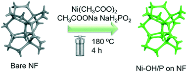
As shown in Scheme 1, Ni–OH/P was fabricated via one-step low-temperature hydrothermal phosphidation using NaH2PO2 as a phosphorus source, CH3COONa as a hydroxide source, and Ni(CH3COO)2 as a nickel source, where 3D macroporous NF acted as a substrate. After phosphidation, the color of NF changed from grey (bare NF) to dark (Ni–OH/P on NF hybrid), and the 3D network-like structure of NF was well preserved, as shown in Fig. S1.† The obtained hybrid was self-supported on NF and could be directly used as an OER anode.The morphological structure and surface composition of Ni–OH/P were probed with transition electron microscopy (TEM), high-resolution TEM (HRTEM), X-ray diffraction (XRD) and X-ray photoelectron spectroscopy (XPS). Fig. 1a shows a portion of Ni–OH/P with some nanosheets on its surface. The relevant HRTEM image (Fig. 1b) shows no lattice fringe, suggesting that its main body is amorphous in nature. The selected area electron diffraction (SAED) image shows diffused halo rings, verifying its amorphous feature. The XRD pattern (Fig. 1c) of Ni–OH/P shows only the diffraction peaks of backbone Ni, indicating that Ni–OH/P is amorphous in nature, which is consistent with the HRTEM and SAED outcomes. The XPS survey spectrum of Ni–OH/P clearly shows the presence of the Ni, P, and O peaks (Fig. S2†). Fig. 1d shows the high-resolution XPS spectrum of Ni 2p spin–orbit, where the peaks of Ni 2p3/2 (855.9 eV) and Ni 2p1/2 (873.5 eV) with a spin-energy separation of 17.6 eV are assigned to Ni2+ from Ni(OH)2.29 Besides, the cyclic voltammogram (Fig. S3†) of Ni–OH/P shows a redox peak of Ni(OH)2/NiOOH,24 confirming the presence of Ni(OH)2 in its surface. Two satellite peaks at 861.6 eV (Ni 2p3/2) and 879.8 eV (Ni 2p1/2) are ascribed to the shakeup peaks of Ni.30,31 In the XPS spectrum of P 2p spin–orbit (Fig. 1e), the distinct peaks at 128.9 and 133.1 eV can be assigned to the phosphide and phosphate species, resulting in the superficial oxidation of nickel phosphides, respectively.32 The O 1s XPS pattern in Fig. 1f shows a peak at 531.3 eV, which is assigned to lattice O of the bridging Ni–O–Ni groups.33 This is the evidence of the existence of the Ni(OH)2 and Ni2+ species.34 The above findings in the O 1s, P 2p, and Ni 2p XPS spectra confirm the formation of the phosphorus-doped Ni(OH)2 hybrid electrocatalyst.
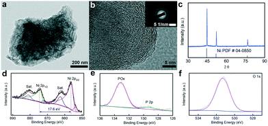 | ||
| Fig. 1 (a) TEM and (b) HRTEM images and (c) XRD pattern of Ni–OH/P. High resolution (d) Ni 2p, (e) P 2p, and (f) O 1s spectra of Ni–OH/P. | ||
Fig. 2a and b show that the hybrid is fully covered by a dense layer of Ni–OH/P on its surface with a thickness of ∼2 um. The layer mainly consists of uniformly dispersed nano-cupcakes (ca. 2 um in diameter) with some nanosheet arrays on their surface (see Fig. 2a and c), which is in accordance with the TEM observation in Fig. 2a. A closer look at Fig. 2d shows that the nanosheet array consists of interconnected nanosheets with void space, facilitating the diffusion of electrolyte ions and desorption of oxygen during OER. Their cupcake- and sheet-like morphologies come from the regulation of NaH2PO2 and CH3COONa, respectively.26 The energy dispersed X-ray spectroscopy (EDS) elemental mapping images of Ni–OH/P verify the homogeneous distribution of the Ni, O, and P elements (Fig. S4a†) and the corresponding linear scan of Ni–OH/P at its cross-sectional view shows that its outer layer is rich in the P and O elements (Fig. S4b†).
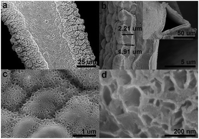 | ||
| Fig. 2 (a, c, and d) Top-down and (b) cross-sectional SEM images of Ni–OH/P. The inset in (b) shows the cross-sectional SEM image of Ni–OH/P at a lower magnification. | ||
3.2 Oxygen evolution activity evaluation
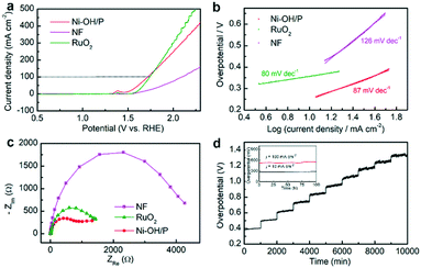
The electrocatalytic OER activities of Ni–OH/P, NF and benchmark RuO2 were first measured in 1 M KOH. Fig. 3a shows their LSV plots. Compared to bare NF and benchmark RuO2, Ni–OH/P showed better OER activity. It required overpotentials of 384 and 490 mV to deliver current densities of 50 and 100 mA cm−2, respectively. Besides, the OER activity of Ni–OH/P was better than that of Ni(OH)2 (ref. 35) or Ni–P,36 which was also supported by our LSV results in Fig. S5a.† The improvement may come from the electronic structure engineering of the anodes by anion regulation (P2−/PO32−/OH−)37 because phosphorus has more electrons for the 3d orbits of Ni than oxygen.38 As shown in Fig. 3b, the Tafel slopes of the three electrodes were calculated to understand the reaction kinetics. Benchmark RuO2 and bare NF have Tafel slopes at 80 and 126 mV dec−1, respectively. Ni–OH/P has a Tafel slope of 87 mV dec−1, which is much lower than that of bare NF and slightly higher than that of RuO2. This confirmed that the better OER kinetics of Ni–OH/P than that of NF comes from the directly grown active species.Then, the electrochemical active surface area (ECSA) of Ni–OH/P was measured by its electrochemical double-layer capacitance (Cdl) to uncover its intrinsic activity. It possessed a Cdl value of 12.03 mF cm−2 (Fig. S5c†), suggesting high ECSA and thereby a good exposure of its active sites. The EIS curves (Fig. 3c) of the three electrodes were also recorded to understand the charge transfer during the reaction process. Ni–OH/P presents the smallest semicircle diameter relating to the best charge transferability among all the electrodes. It is believed that the good charge transferability of an electrode leads to the promotion of the electrolytic process and the enhancement of the electrolytic activity.39 Besides its good OER activity, Ni–OH/P has high stability for electrocatalytic OER. Fig. 3d shows the multistep current density measurements of Ni–OH/P. The current densities increase from 50 to 500 mA cm−2 with a rate of 50 mA cm−2/1000 s. At every current density, the corresponding potential immediately becomes steady and undergoes a little change. These quick and stable responses indicate that the as-developed Ni–OH/P has good electrical conductivity, good mechanical strength, and outstanding mass transport during OER.40 The long-term stability tests at 10 and 100 mA cm−2 over 100 h also confirm its robustness and feasibility in practical applications, as shown in the inset of Fig. 3d.
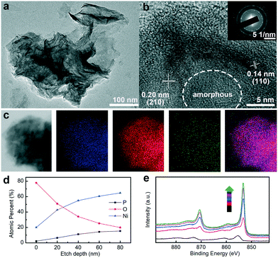
It is well-established that the active species of transition metal phosphide/phosphate would change into the transition metal oxides and (oxy)hydroxides during the long-term OER stability test.41 The structural, compositional, and valence state modifications of Ni–OH/P were probed by TEM, HRTEM, HAADF-STEM, EDS elemental mapping, and XPS. After 100 h of OER at 100 mA cm−2, the nanosheet structure was well preserved (Fig. 4a). The HRTEM image (Fig. 4b) suggests that the central cores remain amorphous, while the outermost surface is transformed into crystalline species with two well-resolved d-spacing values at 0.14 and 0.20 nm, corresponding to the (110) and (105) planes of NiOOH (JCPDS number 06-0075).42 In addition, the SAED pattern shows flecks for crystalline NiOOH and diffuse rings for the amorphous Ni–OH/P core (Fig. 4b inset), which are in agreement with the HRTEM results. The absence of NiOOH (Fig. 1b) in Ni–OH/P before OER implies that the core–shell construction is developed in situ during OER. In addition, the elemental mapping result (Fig. 4c) verifies the preservation of Ni, O, and P in the nanosheet structure, while O is abundant in the marginal sites, which supports the viewpoint mentioned above. The core–shell texture is further confirmed by XPS analysis. As the depth of Ar+ spurting increases, the atomic percentages of Ni and P increase and the percentage of O decreases (Fig. 4d). The high-resolution XPS patterns of Ni 2p at various depths (Fig. 4e) show that the full width at half maximum (FWHM) of the corresponding peak decreases along with the increase in the sputtering depth, implying a stronger metallic character of deep-seated Ni species. The binding energy values are attributed to Ni (oxy)hydroxides and Ni hydroxylphosphate at 0 nm and above 20 nm, respectively.20 The above-mentioned XPS results are, thus, in accordance with that for an Ni–OH/P core underneath an NiOOH shell. The in situ formed NiOOH shell would protect the Ni–OH/P core from further oxidation and the hybrid core might provide fast electron transferability for the shell,43 which ensures the high stability of the electrode without degrading its activity towards OER. Moreover, the formation of crystalline NiOOH on the surface of amorphous Ni–OH/P leads to the construction of an amorphous–crystalline interface, which contributes positively to its water oxidation ability.44
Conclusions
In summary, we developed a low-temperature phosphidation approach for the controllable fabrication of a self-supported phosphorous-doped nickel hydroxide hybrid electrode. In the electrode, 3D porous NF was the core and the directly grown active material film was the shell. The electrode showed enhanced activity and prolonged stability towards OER, benefitting from the high conductivity of NF, synergetic effects between Ni–P and Ni(OH)2, electronic structure engineering of OER active sites by anion regulation, and the in situ formed core–shell structured protective film. Because its compositions are earth-abundant, its construction process is facile, and it has improved OER performance, its scale-up for practice applications is promising.Conflicts of interest
There are no conflicts to declare.Acknowledgements
The project was financially supported by the National Natural Science Foundation of China (Grant No. 21203137, 21476169).Notes and references
- Y. Lee, J. Suntivich, K. J. May, E. E. Perry and Y. Shao-Horn, J. Phys. Chem. Lett., 2012, 3, 399–404 CrossRef CAS.
- F. A. Frame, T. K. Townsend, R. L. Chamousis, E. M. Sabio, T. Dittrich, N. D. Browning and F. E. Osterloh, J. Am. Chem. Soc., 2011, 133, 7264–7267 CrossRef CAS.
- A. Singh and L. Spiccia, Coord. Chem. Rev., 2013, 257, 2607–2622 CrossRef CAS.
- R. Ge, X. Ren, F. Qu, D. Liu, M. Ma, S. Hao, G. Du, A. M. Asiri, L. Chen and X. Sun, Chem. – Eur. J., 2017, 23, 6959–6963 CrossRef CAS PubMed.
- M. W. Kanan, Y. Surendranath and D. G. Nocera, Chem. Soc. Rev., 2009, 38, 109–114 RSC.
- X.-Y. Yu, Y. Feng, B. Guan, X. W. D. Lou and U. Paik, Energy Environ. Sci., 2016, 9, 1246–1250 RSC.
- J. S. Mondschein, J. F. Callejas, C. G. Read, J. Y. Chen, C. F. Holder, C. K. Badding and R. E. Schaak, Chem. Mater., 2017, 29, 950–957 CrossRef CAS.
- Y. Wang, Y. Zhang, Z. Liu, C. Xie, S. Feng, D. Liu, M. Shao and S. Wang, Angew. Chem., Int. Ed., 2017, 56, 5867–5871 CrossRef CAS.
- M. Song, Z. Zhang, Q. Li, W. Jin, Z. Wu, G. Fu and X. Liu, J. Mater. Chem. A, 2019, 7, 3697–3703 RSC.
- L. Trotochaud, J. K. Ranney, K. N. Williams and S. W. Boettcher, J. Am. Chem. Soc., 2012, 134, 17253–17261 CrossRef CAS.
- Y. Chen, K. Rui, J. Zhu, S. X. Dou and W. Sun, Chem. – Eur. J., 2019, 25, 703–713 CrossRef CAS.
- J. Chen, C. Fan, X. Hu, C. Wang, Z. Huang, G. Fu, J.-M. Lee and Y. Tang, Small, 2019, 15, 1901518 CrossRef PubMed.
- Q.-Q. Chen, C.-C. Hou, C.-J. Wang, X. Yang, R. Shi and Y. Chen, Chem. Commun., 2018, 54, 6400–6403 RSC.
- Q. Xie, Z. Cai, P. Li, D. Zhou, Y. Bi, X. Xiong, E. Hu, Y. Li, Y. Kuang and X. Sun, Nano Res., 2018, 1–11 Search PubMed.
- J. Jiang, A. Zhang, L. Li and L. Ai, J. Power Sources, 2015, 278, 445–451 CrossRef CAS.
- N. K. Chaudhari, H. Jin, B. Kim and K. Lee, Nanoscale, 2017, 9, 12231–12247 RSC.
- J. Liu, D. Zhu, Y. Zheng, A. Vasileff and S.-Z. Qiao, ACS Catal., 2018, 8, 6707–6732 CrossRef CAS.
- J.-T. Ren, G.-G. Yuan, C.-C. Weng, L. Chen and Z.-Y. Yuan, Nanoscale, 2018, 10, 10620–10628 RSC.
- Z. Lei, J. Bai, Y. Li, Z. Wang and C. Zhao, ACS Appl. Mater. Interfaces, 2017, 9, 35837–35846 CrossRef CAS PubMed.
- W. Bian, Y. Huang, X. Xu, M. A. Ud Din, G. Xie and X. Wang, ACS Appl. Mater. Interfaces, 2018, 10, 9407–9414 CrossRef CAS.
- S. Cobo, J. Heidkamp, P.-A. Jacques, J. Fize, V. Fourmond, L. Guetaz, B. Jousselme, V. Ivanova, H. Dau and S. Palacin, Nat. Mater., 2012, 11, 802 CrossRef CAS PubMed.
- C. Zhang, C. P. Berlinguette and S. Trudel, Chem. Commun., 2016, 52, 1513–1516 RSC.
- G. Yuan, B. Wen, Y. Hu, G. Zeng, W. Zhang, L. Wang, X. Zhang and Q. Wang, Int. J. Hydrogen Energy, 2019, 44, 14258–14265 CrossRef CAS.
- G. Yuan, L. Wang, X. Zhang and Q. Wang, J. Colloid Interface Sci., 2019, 536, 189–195 CrossRef CAS PubMed.
- G. Yuan, X. Niu, Z. Chen, L. Wang, X. Zhang and Q. Wang, ChemElectroChem, 2018, 5, 2376–2382 CrossRef CAS.
- G. Yuan, Y. Hu, Q. Wang, Z. Wang, L. Wang, X. Zhang and Q. Wang, Inorg. Chem. Front., 2019, 6, 3093–3096 RSC.
- X. Hu, T. Li, Y. Tang, Y. Wang, A. Wang, G. Fu, X. Li and Y. Tang, Chem. – Eur. J., 2019, 25, 7561–7568 CrossRef CAS PubMed.
- Z. Wu, D. Nie, M. Song, T. Jiao, G. Fu and X. Liu, Nanoscale, 2019, 11, 7506–7512 RSC.
- X. Song, X. Li, Z. Bai, B. Yan, D. Li and X. Sun, Nano Energy, 2016, 26, 533–540 CrossRef CAS.
- L. Li, J. Xu, J. Lei, J. Zhang, F. McLarnon, Z. Wei, N. Li and F. Pan, J. Mater. Chem. A, 2015, 3, 1953–1960 RSC.
- Q. Chen, J. Miao, L. Quan, D. Cai and H. Zhan, Nanoscale, 2018, 10, 4051–4060 RSC.
- J. Wang, W. Yang and J. Liu, J. Mater. Chem. A, 2016, 4, 4686–4690 RSC.
- T. Yang, Y. Huo, Y. Liu, Z. Rui and H. Ji, Appl. Catal., B, 2017, 200, 543–551 CrossRef CAS.
- S.-H. Bae, J.-E. Kim, H. Randriamahazaka, S.-Y. Moon, J.-Y. Park and I.-K. Oh, Adv. Energy Mater., 2016, 7, 1601492 CrossRef.
- D. Zhu, J. Liu, L. Wang, Y. Du, Y. Zheng, K. Davey and S. Qiao, Nanoscale, 2019, 11, 3599–3605 RSC.
- A. Han, H. Chen, Z. Sun, J. Xu and P. Du, Chem. Commun., 2015, 51, 11626–11629 RSC.
- J. Duan, S. Chen, A. Vasileff and S. Z. Qiao, ACS Nano, 2016, 10, 8738–8745 CrossRef CAS PubMed.
- B. Wang, C. Tang, H. F. Wang, X. Chen, R. Cao and Q. Zhang, Adv. Mater., 2018, 1805658 Search PubMed.
- F. L. Li, Q. Shao, X. Huang and J. P. Lang, Angew. Chem., 2018, 130, 1906–1910 CrossRef.
- B. Tang, Z. G. Yu, H. L. Seng, N. Zhang, X. Liu, Y.-W. Zhang, W. Yang and H. Gong, Nanoscale, 2018, 10, 20113–20119 RSC.
- J. Xu, J. Li, D. Xiong, B. Zhang, Y. Liu, K.-H. Wu, I. Amorim, W. Li and L. Liu, Chem. Sci., 2018, 9, 3470–3476 RSC.
- H. Liang, J. Lin, H. Jia, S. Chen, J. Qi, J. Cao, T. Lin, W. Fei and J. Feng, J. Power Sources, 2018, 378, 248–254 CrossRef CAS.
- X. Li, G.-Q. Han, Y.-R. Liu, B. Dong, W.-H. Hu, X. Shang, Y.-M. Chai and C.-G. Liu, ACS Appl. Mater. Interfaces, 2016, 8, 20057–20066 CrossRef CAS.
- H. Han, H. Choi, S. Mhin, Y.-R. Hong, K. M. Kim, J. Kwon, G. Ali, K. Y. Chung, M. Je and H. N. Um, Energy Environ. Sci., 2019, 12, 2443–2454 RSC.
Footnote |
| † Electronic supplementary information (ESI) available: SEM, EDS mapping, CV, and LSV. See DOI: 10.1039/c9cy02014d |
| This journal is © The Royal Society of Chemistry 2020 |

