Parallelizable microfluidic dropmakers with multilayer geometry for the generation of double emulsions†
Saraf
Nawar
a,
Joshuah K.
Stolaroff
b,
Congwang
Ye
b,
Huayin
Wu
ac,
Du Thai
Nguyen
b,
Feng
Xin
 ac and
David A.
Weitz
 *ad
*ad
aSchool of Engineering and Applied Sciences, Harvard University, Cambridge, Massachusetts 01238, USA. E-mail: weitz@seas.harvard.edu
bLawrence Livermore National Laboratory, Livermore, California 94550, USA
cSchool of Chemical Engineering and Technology, Tianjin University, Tianjin, 300350, China
dDepartment of Physics, Harvard University, Cambridge, Massachusetts 02138, USA
First published on 21st November 2019
Abstract
Microfluidic devices enable the production of uniform double emulsions with control over droplet size and shell thickness. However, the limited production rate of microfluidic devices precludes the use of monodisperse double emulsions for industrial-scale applications, which require large quantities of droplets. To increase throughput, devices can be parallelized to contain many dropmakers operating simultaneously in one chip, but this is challenging to do for double emulsion dropmakers. Production of double emulsions requires dropmakers to have both hydrophobic and hydrophilic channels, requiring spatially precise patterning of channel surface wettability. Precise wettability patterning is difficult for devices containing multiple dropmakers, posing a significant challenge for parallelization. In this paper, we present a multilayer dropmaker geometry that greatly simplifies the process of producing microfluidic devices with excellent spatial control over channel wettability. Wettability patterning is achieved through the independent functionalization of channels in each layer prior to device assembly, rendering the dropmaker with a precise step between hydrophobic and hydrophilic channels. This device geometry enables uniform wettability patterning of parallelized dropmakers, providing a scalable approach for the production of double emulsions.
Introduction
Double emulsions are droplets which encapsulate smaller droplets. They are used for encapsulation and controlled release1 in a wide range of fields, including medicine, cosmetics, food, and agriculture.2–8 For many applications, production of uniform double emulsion droplets is crucial. Uniformity provides fine control over properties such as release rates of encapsulated cargo. By using microfluidic devices, it is possible to not only produce uniform droplets, but also precisely control other properties including shell thickness and inner droplet number.9,10 Double emulsions are typically formed using microfluidic devices containing two consecutive junctions where immiscible fluids meet. Because industrial-scale applications necessitate large quantities of droplets, it is critical for devices to produce droplets in high volumes. This can be achieved by using a parallelized device, which contains multiple copies of a basic dropmaker geometry. A parallelized device enables the simultaneous production of droplets in its many dropmaker units, making possible higher production throughputs.11–15 Parallelization of double emulsion dropmakers, however, requires achieving correct channel surface wettability properties. This is because drop formation in microfluidic devices requires the continuous phase to preferentially wet the channel, which enables the detachment of dispersed phase drops from the channel walls.16 To produce double emulsions, in which the inner and outer drop are composed of immiscible fluids, the channel wettability must be spatially patterned.17 For the parallelization of double emulsion dropmakers, the channel surface wettability of all dropmakers in the parallelized device must be identically patterned.However, spatial patterning of dropmaker channel wettability is challenging due to the need for highly localized application of surface treatments. This is especially true for single layer microfluidic devices, in which all channels of the dropmaker are located in a single plane. One method frequently utilized to pattern the channel wettability of single layer devices is flow confinement.17 In flow confinement, the liquid containing chemical treatment is carefully flowed through channels of the device requiring functionalization. However, for parallelized devices, application of flow confinement can be extremely difficult, as it requires careful control over the flow profiles of the liquid across all parallel dropmaker units. Another approach is to use photopatterning-based surface modification techniques.18 However, these approaches require careful mask alignment steps to prevent ultraviolet light exposure of undesired regions. This can be challenging to achieve in a precise manner for devices containing many dropmaker units. Thus, there is a need to develop an approach for microfluidic device fabrication that enables precise wettability patterning of channels in parallelized dropmakers.
In this paper, we present an approach for the production of double emulsions using a dropmaker geometry that enables precise spatial patterning of channel surface wettability in both single and parallelized dropmakers. The double emulsion dropmaker consists of a multilayer geometry, with each junction located in a separate plane and containing the necessary wettability character. Because of this geometry, the device can be fabricated in a modular manner that makes the process of patterning channel wettability very facile. The dropmaker enables production of monodisperse double emulsion droplets as well as ease of control over inner droplet, or core number, and shell thickness. This dropmaker geometry is highly advantageous for increasing double emulsion production throughputs. It enables the robust parallelization of dropmakers through the fabrication of devices with uniformly patterned channel surface wettability across parallel dropmakers. Here, we demonstrate the scalability of the device by successfully parallelizing 8 double emulsion dropmaker units.
Results and discussion
We demonstrate a multilayer dropmaker geometry containing precisely patterned channel surface wettability for the robust production of double emulsions. The dropmaker contains two consecutive flow-focusing junctions, each with a distinct wettability character and confined on separate layers of the device. To obtain the precise wettability pattern of the dropmaker channels, we use a modular approach to assemble the device. The modules consist of planar substrates, or layers, containing laser micromachined channel features. These features form the individual junctions of the fully assembled dropmaker, which contains four vertically stacked layers. Layer 1 contains channel features forming the first flow-focusing junction of the device. Layer 2 contains a through-hole, or a vertical channel, which transports single emulsion drops produced in the first junction into the second junction. Layer 3 contains channel features forming the second flow-focusing junction. Layer 3 also contains a vertical channel which serves as the inlet for single emulsion drops produced in the first junction, while layer 4 is completely planar.Layers 1, 2, and 3 also contain additional through-holes which enable the flow of the continuous phase and double emulsion drops between different layers, as shown in the top panel in Fig. 1b. Single emulsion drops of the core phase are formed in the upper layers, and immediately enter the channels in the lower layers, where they are encapsulated to form double emulsion drops, as illustrated by the schematic in the bottom panel in Fig. 1b.
Since the junctions of the dropmaker are located in different layers, channels within modular components can be independently surface modified to achieve the desired wettability character prior to device assembly. Thus, this multilayer dropmaker geometry significantly simplifies the process of producing devices with precisely patterned channel wettability. While channels in the upper layers (layers 1 and 2) are preferentially wet by the shell phase, the channels in the lower layers (layers 3 and 4) are preferentially wet by the continuous phase, as shown in Fig. 1a and b.
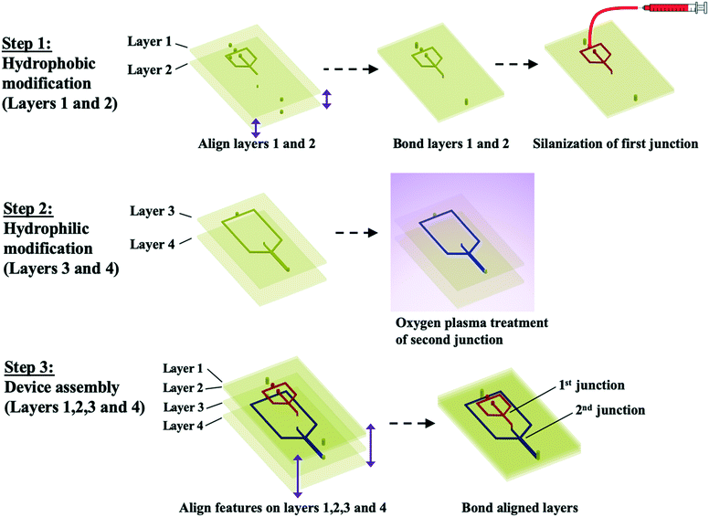
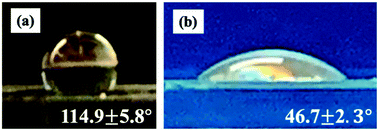
The layers of the device are composed of poly(methyl methacrylate) (PMMA). For the production of water-in-oil (W/O) drops, PMMA channels must be treated to make the surface hydrophobic, which enables detachment of water drops. To make the first flow-focusing junction hydrophobic, we bond layers 1 and 2 together and flow Aquapel silane solution through the channels. Aquapel increases the water contact angle of PMMA, which is 75°,19 to 114.9 ± 5.8°, as shown in Fig. 3a. To form oil-in-water (O/W) drops, PMMA channels must be modified to increase the hydrophilicity, which enables detachment of oil drops. To make the second flow-focusing junction hydrophilic, we treat layers 3 and 4 with oxygen plasma. Oxygen plasma treatment renders PMMA hydrophilic through the generation of polar surface functional groups.20 Thus, oxygen plasma treatment lowers the water contact angle of PMMA to 46.7 ± 2.3°, as shown in Fig. 3b. Following surface functionalization, we bond all the layers together. Prior to the bonding process, through-holes in different layers are carefully aligned since mismatch between these vertical channels can inhibit the flow of fluids between different layers. The resulting dropmaker, shown in Fig. 1c, contains an abrupt transition between hydrophobic and hydrophilic channels. This modular assembly approach is illustrated by the schematic in Fig. 2.
To demonstrate the effectiveness of the dropmaker, we form W/O/W double emulsions using mineral oil containing 2% (w/v) sorbitan oleate (SPAN 80) surfactant as the middle phase. For the inner and outer phase, we use 1% (w/v) and 10% (w/v) aqueous solutions of poly(vinyl alcohol) (PVA, Mw 13![[thin space (1/6-em)]](https://www.rsc.org/images/entities/char_2009.gif) 000–23
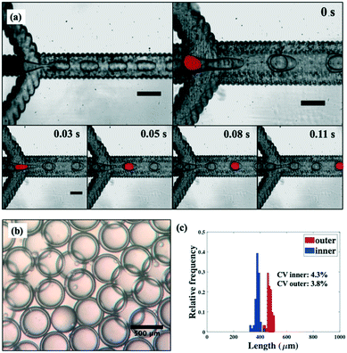
000–23![[thin space (1/6-em)]](https://www.rsc.org/images/entities/char_2009.gif) 000), respectively. Although the two droplet breakup steps occur in different layers of the device, drops produced in the upstream junction approach the downstream junction one-by-one, in an ordered manner. Consequently, flow rate of the continuous phase at the downstream junction can be easily tuned to ensure the encapsulation of a single drop of the core phase. Optical micrographs of the step-wise droplet breakup process for forming single-core W/O/W double emulsions are shown in Fig. 4a and Movie S1.† The dropmaker produces highly monodisperse W/O/W double emulsions, as shown by the optical microscope image in Fig. 4b. Here, W/O/W double emulsions are produced at flow rates of 2000, 2000 and 13
000), respectively. Although the two droplet breakup steps occur in different layers of the device, drops produced in the upstream junction approach the downstream junction one-by-one, in an ordered manner. Consequently, flow rate of the continuous phase at the downstream junction can be easily tuned to ensure the encapsulation of a single drop of the core phase. Optical micrographs of the step-wise droplet breakup process for forming single-core W/O/W double emulsions are shown in Fig. 4a and Movie S1.† The dropmaker produces highly monodisperse W/O/W double emulsions, as shown by the optical microscope image in Fig. 4b. Here, W/O/W double emulsions are produced at flow rates of 2000, 2000 and 13![[thin space (1/6-em)]](https://www.rsc.org/images/entities/char_2009.gif) 000 μl h−1 for the inner, middle and outer phase, respectively. We analyse at least 60 double emulsion drops to assess the size distribution of drops, as shown by the histogram of the inner and outer diameters in Fig. 4c. Double emulsions produced have a narrow size distribution, with coefficient of variance (CV) ∼4% for both the inner and outer diameter.
000 μl h−1 for the inner, middle and outer phase, respectively. We analyse at least 60 double emulsion drops to assess the size distribution of drops, as shown by the histogram of the inner and outer diameters in Fig. 4c. Double emulsions produced have a narrow size distribution, with coefficient of variance (CV) ∼4% for both the inner and outer diameter.
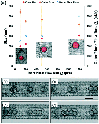
We investigate the effect of varying dispersed and continuous phase flow rates on the structural parameters of the resulting double emulsion drops. To tune the size of the core drops encapsulated, we vary the inner phase flow rate Qi from 100 to 1200 μl h−1 while keeping the shell phase flow rate Qm constant at 1000 μl h−1. As Qi is gradually increased, we form double emulsion drops with larger core sizes, from 199 μm (Qi = 100 μl h−1) to 308 μm (Qi = 1200 μl h−1), as shown in Fig. 5a. Simultaneously, the outer phase flow rate Qo is adjusted for each value of Qi to ensure the encapsulation of a single core phase drop within each shell phase drop. Since Qo must be increased for higher values of Qi, the outer drop size decreases from 544 to 420 μm as Qo is varied from 2500 to 5000 μl h−1, as shown in Fig. 5a. In turn, the relative size of the core phase drop to the shell phase drop nearly doubles from 0.37 to 0.73, resulting in the formation of double emulsion drops with thinner shells.
We also form double emulsions with different numbers of core phase drops. We do this by tuning Qo while keeping both Qi and Qm constant at 1000 μl h−1. For a higher value of Qo = 3500 μl h−1, we form double emulsions with a single core, as shown in Fig. 5b. Here, droplet breakup at the downstream junction occurs at a high frequency due to the high shear applied by the outer phase. The result is the encapsulation of only one core phase drop per double emulsion drop. However, when we decrease Qo to 2500 μl h−1, droplet breakup frequency decreases, so that two core phase drops are encapsulated, as shown in Fig. 5c. Further decreases of the outer phase flow rate to 2000 μl h−1 and 1600 μl h−1 produce double emulsions with three and four core phase drops, respectively (Fig. 5d and e).
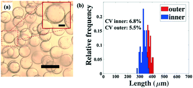
The dropmaker can be utilized to produce microcapsules, which are formed using double emulsion drops as templates. To generate microcapsules, we solidify the shell phase by crosslinking the monomers constituting the droplet shell. To produce the microcapsules, we use a sodium carbonate (Na2CO3) solution as the core phase and a crosslinkable silicone acrylate liquid containing photoinitiator as the shell phase. For the continuous phase, we use an aqueous solution of 10% (w/v) PVA. Double emulsions are formed at flow rates of 300, 500, and 12![[thin space (1/6-em)]](https://www.rsc.org/images/entities/char_2009.gif) 000 μl h−1 for the core, shell and continuous phase, respectively, and are collected in 1% (w/v) PVA solution. The collected double emulsions are crosslinked upon exposure to ultraviolet light, which photopolymerizes the shell phase. The resulting microcapsules are monodisperse, as shown in Fig. 6a. The size distribution of the inner and outer diameters of the microcapsules illustrates their uniformity, with relatively small spread shown by each histogram, as shown in Fig. 6b. The average inner and outer diameters of the microcapsules are 379.9 μm (CV = 6.8%) and 470.5 μm (CV = 5.5%), respectively.
000 μl h−1 for the core, shell and continuous phase, respectively, and are collected in 1% (w/v) PVA solution. The collected double emulsions are crosslinked upon exposure to ultraviolet light, which photopolymerizes the shell phase. The resulting microcapsules are monodisperse, as shown in Fig. 6a. The size distribution of the inner and outer diameters of the microcapsules illustrates their uniformity, with relatively small spread shown by each histogram, as shown in Fig. 6b. The average inner and outer diameters of the microcapsules are 379.9 μm (CV = 6.8%) and 470.5 μm (CV = 5.5%), respectively.
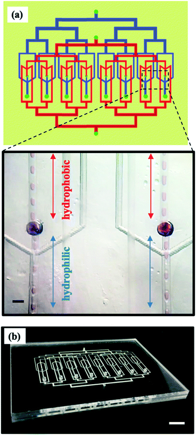
The multilayer geometry is advantageous for increasing double emulsion production throughput. Its modular fabrication approach can be used to produce parallelized devices in which all dropmakers have identically patterned channel wettability. To demonstrate the utility of the approach for parallelization, we incorporate eight dropmakers in a single chip. The parallelized device consists of four PMMA layers. To fabricate the device, modular components containing parallelized channel features are independently surface treated and assembled together. Channels in layers 1 and 2 are treated hydrophobically, while channels in layers 3 and 4 are treated hydrophilically. The assembled device consists of eight parallelized dropmakers with identical regions of hydrophobicity and hydrophilicity, which are located in separate layers, as shown in Fig. 7a and b. In each dropmaker, W/O drops form in layers with hydrophobic channels and are encapsulated to form W/O/W double emulsion drops in layers with hydrophilic channels, as shown in the inset in Fig. 7a. The inner, middle and outer phase fluids are each supplied from a single inlet and distributed to each dropmaker through branched channels consisting of a series of bifurcations, as shown in Fig. 7a and b. This channel structure provides uniform distribution of fluid phases to each dropmaker.21 Furthermore, the distribution channels are much wider closer to the inlets than they are near the junctions of the individual dropmakers. This channel design minimizes the resistance that the fluids encounter as they are being distributed to the junctions of the device.11
All dropmakers in the parallelized device form double emulsions, as shown by the panels in Fig. 8a. Here, the inner phase and middle phase are each supplied at 10 mL h−1, while the outer phase is supplied at 20 mL h−1. Double emulsions produced using the device are shown in the optical microscope image in Fig. 8b. Size distributions of the double emulsions produced, shown in the histograms in Fig. 8c, are slightly broader than those obtained using a single dropmaker device. We attribute this increase in size distribution to several factors, including the inhomogeneous distribution of fluid phases across the parallel dropmakers, which can affect droplet breakup rates, especially for dropmakers at the edge of the device. This can be addressed through improvements in device geometry, such as by further decreasing the hydrodynamic resistance of the channels in the branched distribution network through the use of much wider channels. Alternatively, the dropmakers can be packed closer together, thus decreasing the length of the channels in the distribution network. Another factor could be heterogeneities in channel size due to the laser micromachining process used to fabricate dropmaker features. This can be rectified by using alternative processes for channel fabrication, such as injection moulding. Nevertheless, we find parallelized operation to yield good drop uniformity, with CV for the inner and outer diameters at 6.9% and 6.7%, respectively. For the parallelized device, the total throughput, defined as the sum of the inner and middle phases, is 20 ml h−1, equating to a production rate of 0.48 L per day. By parallelizing more dropmakers in the same chip, further increases in production rates can be possible. From a linear extrapolation, we estimate that a device containing 800 parallelized dropmakers of the same geometry could generate double emulsion drops at rates close to 50 L per day. While previous reports have described the parallelization of dropmakers to produce single22 and multiple emulsions, such as compound bubbles,23 the platform described here provides significant advantages. In particular, the ability to produce parallelized dropmakers with identically spatially patterned regions of hydrophobicity and hydrophilicity markedly expands the types of compound emulsion drops that can be produced at higher throughputs using microfluidic dropmakers.
Experimental
Device fabrication
To produce microfluidic channel features, continuous cast acrylic sheets (McMaster-Carr, IL) are micromachined using a PLS6.60 laser system (universal laser systems). The system is equipped with a CO2 laser operating at 60 W in full power mode with a maximum resolution of 1000 DPI. We use vector mode to cut the PMMA sheets into the desired substrate shapes, while we use raster mode to generate channel features. Following the laser ablation process, PMMA substrates are cleaned using isopropanol and dried at 65 °C for at least 30 minutes prior to use.To produce the first junction of the dropmaker, a PMMA substrate containing flow-focusing channel features is bonded to a PMMA substrate containing only through-holes. After bonding the substrates, we treat this this junction hydrophobically by applying Aquapel solution (PPG Industries) to the channels within the two mated layers. Aquapel in solution form is typically used within 2–3 days after removal from its original packaging. To prevent degradation of the coating agent, the stock solution is stored in a hermetically closed container at room temperature. Channels are functionalized with Aquapel solution for 10 min, after which Aquapel is flushed out using air. Following functionalization using Aquapel, the bonded layers are placed in a 65 °C oven for at least 15 min.
The second junction of the dropmaker is composed of two PMMA substrates, one containing flow-focusing channel features and the other planar. To make the channels of this junction hydrophilic, we modify the surface of the PMMA substrates by applying oxygen plasma (Plasma Etch, PE-50 HF, NV) treatment at 80 W for 30 s. Oxygen plasma treatment is done prior to bonding the substrates.
After channels on individual substrates are surface functionalized, the substrates, or layers, are assembled together. During assembly, we ensure good alignment of the through-holes, or vertical channels connecting different layers. We bond PMMA layers together using a hot press (Auto Series Plus Model Presses, Carver). We use a solvent-facilitated bonding process.24 Here, we apply a few drops of a solvent mixture containing 47.5% dimethyl sulfoxide (DMSO), 47.5% deionized water, and 5% methanol (MeOH) to the surface of the PMMA substrates being bonded. Since layers 1 and 2 are bonded beforehand, to assemble the full dropmaker, the solvent is now applied to the bottom side of layer 2, both sides of layer 3, and the top side of layer 4. We bond the solvent-treated substrates at 85 °C using an applied force of 5000 N for 30 min.
Device operation
Double emulsions are produced using 1% (w/v) PVA solution for the inner phase, light mineral oil with 2% (w/v) SPAN 80 for the middle phase, and 10% (w/v) PVA solution for the continuous phase. Fluid phases used to produce double emulsion drops are introduced into the device using syringe needle tips glued onto through-holes on the topmost PMMA layer. Formation of double emulsions is observed using an inverted microscope. Drops are collected in a 1% (w/v) PVA solution and imaged using an upright optical microscope. Drop sizes are analysed using ImageJ image processing software.Conclusions
We describe microfluidic devices with spatially patterned wettability to produce double emulsions. The multilayer dropmaker is easily fabricated in a modular manner and enables precise wettability patterning of both single and parallelized devices. We believe there are a wide range of potential applications for this platform. For example, by adding more layers, we will be able to utilize this platform to produce higher-order emulsions, such as triple emulsions. Another potential application is to invert the wettability of the junctions to produce oil-in-water-in-oil double emulsions. In addition, the method can be utilized to produce dropmakers with patterned channels composed of a wide range of surface chemistries. For example, while we used oxygen plasma treatment to render the PMMA surface hydrophilic, the contact angle of the surface increases after a few days. The rate of hydrophobic recovery, however, can be reduced by increasing the duration of oxygen plasma treatment, which creates a nanotextured superhydrophilic surface, or by coating the surface with a hydrophilic polymer following plasma processing.19,25 This can significantly improve the reusability of the device over a longer period of time. Furthermore, the method can be applied to other thermoplastics, including cyclic olefin copolymer and polycarbonate. These thermoplastics can be formed using high-volume manufacturing techniques, thus enabling large-scale chip production.Significantly, this approach markedly simplifies wettability patterning in parallelized dropmakers, enabling increased double emulsion production throughput without significantly compromising the uniformity. By adding more dropmakers in the parallelized device, we can further increase the throughput. This platform will is expected to enable the production of multiple emulsions composed of a wide array of materials at high volume quantities necessary for their industrial-scale utilization.
Conflicts of interest
There are no conflicts to declare.Acknowledgements
We acknowledge support from the National Science Foundation (DMR-1708729) and the Harvard Materials Research Science and Engineering Center (MRSEC) (DMR-1420570). S. N. acknowledges support from the Department of Energy (DE-AC52-07NA27344). This work was performed in part at the Center for Nanoscale Systems (CNS), a member of the National Nanotechnology Coordinated Infrastructure Network (NNCI), which is supported by the National Science Foundation under NSF award no. 1541959. CNS is part of Harvard University.Notes and references
- A. K. L. Oppermann, L. C. Verkaaik, M. Stieger and E. Scholten, Food Funct., 2017, 8, 522–532 RSC.
- J. Pessi, H. A. Santos, I. Miroshnyk, J. Yliruusi, D. A. Weitz and S. Mirza, Int. J. Pharm., 2014, 472, 82–87 CrossRef CAS PubMed.
- K. Tsuiji, J. Microencapsulation, 2001, 18, 137–147 CrossRef PubMed.
- A. M. Bakry, S. Abbas, B. Ali, H. Majeed, M. Y. Abouelwafa, A. Mousa and L. Liang, Compr. Rev. Food Sci. Food Saf., 2016, 15, 143–182 CrossRef CAS.
- H. Lee, C. H. Choi, A. Abbaspourrad, C. Wesner, M. Caggioni, T. Zhu and D. A. Weitz, ACS Appl. Mater. Interfaces, 2016, 8, 4007–4013 CrossRef CAS PubMed.
- M. E. Carlotti, M. Gallarate, S. Sapino, E. Ugazio and S. Morel, J. Dispersion Sci. Technol., 2005, 26, 183–192 CrossRef CAS.
- D. S. Mahrhauser, C. Fischer and C. Valenta, Int. J. Pharm., 2016, 498, 130–133 CrossRef CAS PubMed.
- Y. Hemar, L. J. Cheng, C. M. Oliver, L. Sanguansri and M. Augustin, Food Biophys., 2010, 5, 120–127 CrossRef.
- A. S. Utada, Science, 2005, 308, 537–541 CrossRef CAS PubMed.
- W. J. Duncanson, T. Lin, A. R. Abate, S. Seiffert, R. K. Shah and D. A. Weitz, Lab Chip, 2012, 12, 2135–2145 RSC.
- M. B. Romanowsky, A. R. Abate, A. Rotem, C. Holtze and D. A. Weitz, Lab Chip, 2012, 12, 802–807 RSC.
- T. Femmer, A. Jans, R. Eswein, N. Anwar, M. Moeller, M. Wessling and A. J. C. Kuehne, ACS Appl. Mater. Interfaces, 2015, 7, 12635–12638 CrossRef CAS PubMed.
- T. Nisisako, T. Ando and T. Hatsuzawa, Lab Chip, 2012, 12, 3426–3435 RSC.
- E. Amstad, M. Chemama, M. Eggersdorfer, L. R. Arriaga, M. P. Brenner and D. A. Weitz, Lab Chip, 2016, 16, 4163–4172 RSC.
- E. Amstad, ACS Macro Lett., 2017, 841–847 CrossRef CAS.
- H. Gu, M. H. G. Duits and F. Mugele, Int. J. Mol. Sci., 2011, 12, 2572–2597 CrossRef CAS PubMed.
- A. R. Abate, J. Thiele, M. Weinhart and D. A. Weitz, Lab Chip, 2010, 10, 1774–1776 RSC.
- A. R. Abate, A. T. Krummel, D. Lee, M. Marquez, C. Holtze and D. A. Weitz, Lab Chip, 2008, 8, 2157–2160 RSC.
- H. Yu, Z. Z. Chong, S. B. Tor, E. Liu and N. H. Loh, RSC Adv., 2015, 5, 8377–8388 RSC.
- R. Landgraf, M. Kaiser, J. Posseckardt, B. Adolphi and W. Fischer, Procedia Chem., 2009, 1, 1015–1018 CrossRef CAS.
- M. L. Eggersdorfer, W. Zheng, S. Nawar, C. Mercandetti, A. Ofner, I. Leibacher, S. Koehler and D. A. Weitz, Lab Chip, 2017, 17, 936–942 RSC.
- S. Yadavali, H. Jeong, D. Lee and D. Issadore, Nat. Commun., 2018, 9, 1222 CrossRef PubMed.
- D. Issadore and D. Lee, Lab Chip, 2019, 19, 665–673 Search PubMed.
- L. Brown, T. Koerner, J. H. Horton and R. D. Oleschuk, Lab Chip, 2006, 6, 66–73 RSC.
- K. Tsougeni, N. Vourdas, A. Tserepi, E. Gogolides, M. Jean, R. Imn and R. De Houssiniere, Langmuir, 2009, 25, 11748–11759 CrossRef CAS PubMed.
Footnote |
| † Electronic supplementary information (ESI) available: Movie of double emulsion generation using multilayer dropmaker (S1) and design file for the device layers. See DOI: 10.1039/c9lc00966c |
| This journal is © The Royal Society of Chemistry 2020 |


