 Open Access Article
Effective suppression of lithium dendrite growth using fluorinated polysulfonamide-containing single-ion conducting polymer electrolytes†
Yunyun
Zhong
a,
Jianwei
Zhang
a,
Shuanjin
Wang
a,
Dongmei
Han
b,
Min
Xiao
*a and
Yuezhong
Meng
 *a
*a
aThe Key Laboratory of Low-carbon Chemistry & Energy Conservation of Guangdong Province/State Key Laboratory of Optoelectronic Materials and Technologies, School of Materials Science and Engineering, Sun Yat-sen University, Guangzhou 510275, P. R. China. E-mail: mengyzh@mail.sysu.edu.cn; stsxm@mail.sysu.edu.cn
bSchool of Chemical Engineering and Technology, Sun Yat-sen Univeristy, Zhuhai 519082, P. R. China
First published on 11th June 2020
Abstract
The lithium metal anode, which is considered as the “Holy Grail” anode material, possesses extra high energy density and extra low negative electrochemical potential. However, it is hardly applied in lithium batteries owing to lithium dendrite formation and interfacial instability in the electrolyte, resulting in safety problems and poor long-cycle performance. In this work, we designed and synthesized a novel artificial solid electrolyte interface (SEI) layer, which exhibits high ionic conductivity and single-ion conductive characteristics. The SEI layer named LiSFSI-PET4A-PETMP (LFPP) SEI layer was synthesized by a one-step click reaction in situ on the surface of lithium metals using lithium[(4-styrenesulfonyl) (fluorosulfonyl)imide] (LiSFSI), pentaerythritol tetraacrylate (PET), and pentaerythritol tetrakis (2-mercaptoacetate) (PETMP). The formed LFPP-SEI layer has a controllable 3D cross-linked network structure. It also exhibits high ionic conductivity and high lithium ion transference number near to unity, which is beneficial for preventing the nucleation of lithium dendrites, so as to suppress the formation of lithium dendrites from the source. The Li//LFP full cell using LFPP 2%-Li anode exhibits a quite high and stable capacity with a capacity retention of 75.8% and a high coulombic efficiency of 99.0% at 1C after 390 cycles. Moreover, the full battery using an LFPP 2%-Li anode and an LFPP 1%-Li anode at 0.5C for 250 cycles shows a very good coulombic efficiency of 100.0% and capacity retention values of 77.5% and 77.7%, respectively.
Introduction
The application of lithium metal anodes has been a research focus for its extra high energy density of 3860 mA h g−1 and extra low negative electrochemical potential of −3.04 V versus standard hydrogen electrodes.3 However, it is hardly applied in lithium batteries owing to lithium dendrite formation and interfacial instability in the electrolyte, resulting in safety problems and poor long-cycle performance.1,2 In addition, it suffers from volume expansion during cycle performance, which can also weaken the cycle performance.4–6In recent years, much effort has been devoted to suppressing the lithium dendrite formation.7–9 A native solid electrolyte interface (SEI) layer between the liquid electrolyte and the lithium metal can spontaneously shape up due to the high reactivity of the electrolyte solvent, such as cyclic carbonate (e.g., ethylene carbonate, EC) and cyclic ether (e.g., 1,3-dioxolane, DOL). But the native SEI layer exhibits low ionic conductivity (4.2 × 10⁻⁸ S cm−1),10 structural instability and chemical heterogeneity,11 which induce heterogeneous electrodeposition resulting in dendrite growth. Many studies have disclosed various measures such as use of solid electrolytes or gel electrolytes,4,8,12–16 construction of an artificial solid electrolyte interface (SEI) layer,17–23,54 design of functionalized separators,24–30 and improvement of the structure of current collectors2,31–37 to suppress the formation and growth of lithium dendrites. Construction of an artificial SEI layer is one good solution to solve the challenge of suppressing the formation and growth of lithium dendrites. Many kinds of artificial SEI layers such as poly(vinylidene-co-hexa-fluoropropylene)(PVDF-HFP)/LiF,38 Al2O3 sputter coating,39 Li polyacrylic acid (LiPAA),40 polyvinylidene difluoride (PVDF),41 LLZTO/Li-Nafion dual-phase SEI,42 Li polylactic acid (LiPLA),8 LiAlO2,43 poly(ethylene vinyl alcohol-β-acrylonitrile ether) (EVOH-β-OCH2CH2CN, abbreviated as EBC)/lithium bis-trifluoromethyl sulfonate (LiTFSI),44 Li3PO4,45 graphene oxide (GO),46 covalent organic frameworks (COFs),47 and graphene/LiF48 have been reported. The artificial SEI layer mentioned above can largely stabilize the active lithium metal anode; however, most of them exhibit extremely low ionic conductivity or even ionic insulation. The work by Tikekar et al. showed that the stable SEI layer should have the following characteristics: high ionic conductivity under strong bias, large shear modulus of the Interphase and sufficiently small size of the initial nucleates.49
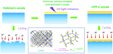
Herein, we report a novel artificial SEI layer (Fig. 1) exhibiting extra high ionic conductivity (0.0927 mS cm−1) and lithium ion transference number near to unity (0.91). The LFPP-SEI can form a uniform film on the surface of the Li anode with good flexibility and high mechanical strength. The extra high ionic conductivity and lithium ion transference number of the SEI layer can weaken or even eliminate the anion depletion–induced strong electric fields on the surface of the lithium anode to inhibit the nucleation of lithium dendrites, so as to suppress the formation of lithium dendrites from the root. The galvanostatic plating/stripping cycling performance of the symmetric cell with LFPP 1%-Li exhibits a quite stable over potential at 0.038 V for over 1000 h, indicating the superior stability of the LFPP SIPE-coated Li anode. The full LFP batteries with LFPP-Li anodes exhibit a very high coulombic efficiency of 100.0% on average and a capacity retention of 77.7% for 250 cycles.
Results and discussion
1. Ionic conductivity
In our precious study, the ionic conductivity of LFPP with electrospun PVDF as a standing membrane soaked with DMC/EC (vol% = 1![[thin space (1/6-em)]](https://www.rsc.org/images/entities/char_2009.gif) :
:![[thin space (1/6-em)]](https://www.rsc.org/images/entities/char_2009.gif) 1) is up to 5.1 × 10⁻³ S cm−1. To further investigate the ionic conductivity of the LFPP artificial SEI layer soaked with the solvent, the EIS analysis was carried out in symmetric coin cells assembled by two LFPP-coated stainless steel round electrodes soaked in DMC/EC/EMC (vol% = 1
1) is up to 5.1 × 10⁻³ S cm−1. To further investigate the ionic conductivity of the LFPP artificial SEI layer soaked with the solvent, the EIS analysis was carried out in symmetric coin cells assembled by two LFPP-coated stainless steel round electrodes soaked in DMC/EC/EMC (vol% = 1![[thin space (1/6-em)]](https://www.rsc.org/images/entities/char_2009.gif) :
:![[thin space (1/6-em)]](https://www.rsc.org/images/entities/char_2009.gif) 1
1![[thin space (1/6-em)]](https://www.rsc.org/images/entities/char_2009.gif) :
:![[thin space (1/6-em)]](https://www.rsc.org/images/entities/char_2009.gif) 1) using a PP membrane (Celgard 2500) as the separator.50
1) using a PP membrane (Celgard 2500) as the separator.50
The LFPP SEI layer was prepared by a one-step in situ click reaction on the surface of the stainless steel (SS) electrode. A series of LFPP SEI layers with various thicknesses were fabricated by simply adjusting the mass concentration of precursors, consisting of LiSFSI, PET4A and PETMP in DMC/EC/EMC (vol% = 1![[thin space (1/6-em)]](https://www.rsc.org/images/entities/char_2009.gif) :
:![[thin space (1/6-em)]](https://www.rsc.org/images/entities/char_2009.gif) 1
1![[thin space (1/6-em)]](https://www.rsc.org/images/entities/char_2009.gif) :
:![[thin space (1/6-em)]](https://www.rsc.org/images/entities/char_2009.gif) 1). The thickness of the LFPP SEI layers is not directly determined using a scanning electron microscope (SEM), because the section of SS round electrode is too thick and hard to cut off. It was calculated from the thickness of the LFPP coating on the Cu foil, which is more accessible. As the LFPP/DMC precursor solution exhibits different diffusibilities, their volumes dropped onto the Li and Cu foils are 45 μL and 20 μL respectively. Given that the areas of the Cu and SS foil are identical, the LFPP layer on the SS round electrode is 2.25 times as thick as that on the Cu foil. The thickness of the LFPP layer on the Cu foil can be obtained, as shown in Fig. S1 and Table S1 (ESI†).
1). The thickness of the LFPP SEI layers is not directly determined using a scanning electron microscope (SEM), because the section of SS round electrode is too thick and hard to cut off. It was calculated from the thickness of the LFPP coating on the Cu foil, which is more accessible. As the LFPP/DMC precursor solution exhibits different diffusibilities, their volumes dropped onto the Li and Cu foils are 45 μL and 20 μL respectively. Given that the areas of the Cu and SS foil are identical, the LFPP layer on the SS round electrode is 2.25 times as thick as that on the Cu foil. The thickness of the LFPP layer on the Cu foil can be obtained, as shown in Fig. S1 and Table S1 (ESI†).
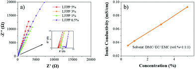
The EIS curves and ionic conductivity calculation results are shown in Fig. 2 and Table S1 (ESI†), respectively. The ionic conductivity is very high up to 0.0927 mS cm−1 in DMC/EC/EMC (vol% = 1![[thin space (1/6-em)]](https://www.rsc.org/images/entities/char_2009.gif) :
:![[thin space (1/6-em)]](https://www.rsc.org/images/entities/char_2009.gif) 1
1![[thin space (1/6-em)]](https://www.rsc.org/images/entities/char_2009.gif) :
:![[thin space (1/6-em)]](https://www.rsc.org/images/entities/char_2009.gif) 1), which is much higher than that of the reported routine SEIs (4.2 × 10⁻⁸ S cm−1).10 It can be seen that a higher ionic conductivity can be readily achieved by increasing the concentration of precursors, as shown in Fig. 2.
1), which is much higher than that of the reported routine SEIs (4.2 × 10⁻⁸ S cm−1).10 It can be seen that a higher ionic conductivity can be readily achieved by increasing the concentration of precursors, as shown in Fig. 2.
2. Electrochemical stability
The electrochemical stability of the electrode material determines the voltage range of lithium-ion batteries. In this work, the electrochemical stability of the LFPP SEI layer in carbonate electrolytes was measured by linear sweep voltammetry (LSV) in 2032 coin cells using stainless steel as the cathode and LFPP-Li as the anode (LFPP-Li//SS) and using a carbon cathode and LFPP-Li as the anode (Super P//LFPP-Li). The LSV measurement was carried out from 0 V to 6.0 V at a scan speed of 1 mV s−1. As shown in Fig. 3a, the LFPP SEI layer is electrochemically stable up to 5.2 V. To further investigate the electrochemical stability of the LFPP SEI layer applied in carbonate electrolytes, the cyclic voltammetry was performed in a voltage range of 2.5–4.2 V at a scan speed of 1 mV s−1, as shown in Fig. S4 (ESI†), indicating no obvious redox peaks. It is also confirmed that the LFPP SEI layer is electrochemically stable from 2.5 V to 4.2 V, which can then guarantee its extensive application in lithium batteries. When the electrochemical stability of the LFPP SEI layer was tested using a stainless steel foil as the working electrode, the resultant electrochemical stability window was always over-estimated. A carbon-based electrode is used in Fig. 3b. The electrochemical stability is up to 5.7 V.51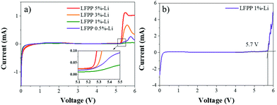 | ||
| Fig. 3 Linear sweep voltammetry curves: (a) LFPP SEI layer in LFPP-Li//SS batteries and (b) LFPP SEI layer in a Super P//LFPP-Li battery. | ||
3. Galvanostatic Li plating/stripping cycling behaviors
To further investigate the influence of the LFPP SEI layer coated on a Li metal anode, galvanostatic cycling performance was evaluated in a symmetric LFPP-Li cell. The galvanostatic cycling of symmetric LFPP-Li||LFPP-Li cells was tested at a current density of 0.5 mA cm−2 with a capacity of 1 mA h cm−2. As shown in Fig. 4, the over-potential of the cells with LFPP-Li increases with the increase in the concentration of LFPP precursors, owing to the increase in the thickness of the LFPP SEI layer. When the concentrations of the LFPP precursor are 5% and 2%, the galvanostatic cycling performance is stable at 0.7–1.0 V for about 950 h. After about 1100 h, the over-potential bumps up sharply, which can be attributed to the lithium dendrite formation and the incrassated SEI layer.40 Moreover, the SFSI anion of LiSFSI salt is uniformly distributed on the surface of the lithium anode, which can guide Li+ to distribute and deposit evenly. The symmetric cell with LFPP 1%-Li exhibits the lowest and most stable over-potential at 0.038 V for over 1000 h. The outstanding cycling performance of the symmetric LFPP-Li cells with the LFPP 1%-Li SEI layer demonstrates the superior stability and lithium ion transport ability of the LFPP SEI layer.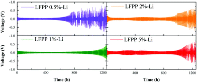 | ||
| Fig. 4 Galvanostatic cycling performance of symmetric LFPP-Li||LFPP-Li cells at a current density of 0.5 mA cm−2 with a capacity of 1 mA h cm−2. | ||
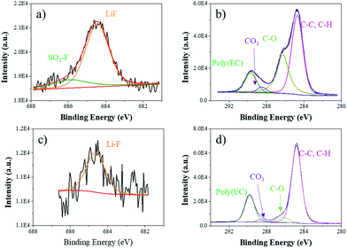
Furthermore, XPS analysis was operated to explore the stability of the interface enhanced by LFPP SEI layers by investigating the chemical compositions on the surface of the lithium anode. Fig. 5 shows the XPS spectra for the anodes retrieved from symmetric lithium cell-based carbonate electrolytes with LFPP-Li. Comparing the anode from symmetric lithium cells with a polished Li anode after cycling for 200 h at 0.5 mA cm−2 with a capacity of 1 mA h cm−2, there are SO2–F (685.9 eV) and more abundant Li–F (684.4 eV) and C–O (286.3 eV) on the anode surface, which is in accordance with the chemical composition of the LFPP SEI layer.52 It can be seen that the C–C, C–H peak (284.8 eV, C 1s), C–O peak (286.3 eV, C 1s), CO3 peak (288.6 eV, C 1s), poly(EC) peak (289.8 eV, C 1s), and Li–F peak (684.4 eV, F 1s) appear on the surface of the polished Li anode in a symmetric lithium cell after cycling, which are the typical composition for the native solvent-induced SEI formation. However, it has been proved that the native SEI layer induced by electrolytes is unstable, which can then tolerate chemical heterogeneity, inducing heterogeneous electrodeposition and generating dendrite growth.11
4. Battery performance
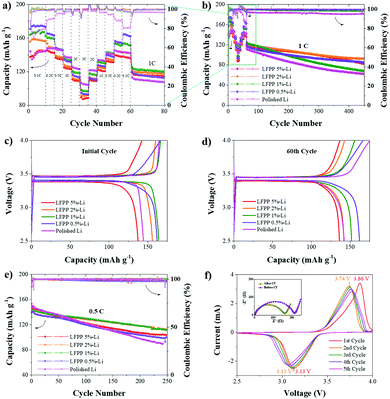
The battery performance and cyclic voltammetry curves of Li//LiFePO4 cells with LFPP-Li and polished Li anodes are shown in Fig. 6, respectively. Fig. 6a and b describe the rate performance of Li//LFP full batteries using the LFPP-Li anode and the polished Li anode. At a low rate, LFPP-Li//LFP batteries using LFPP-Li anodes exhibit better performance than the Li//LFP batteries using polished Li anodes. The battery using LFPP 0.5%-Li as the anode exhibits the best performance. This may be because the LFPP SEI layer exhibits good compatibility with liquid electrolytes and it has a very high lithium ion transference number near to unity, which can weaken or even eliminate the anion depletion-induced strong electric fields on the lithium anode. It is further proved that, by the charge–discharge curves of the initial cycle (Fig. 6a) and the 60th cycle of the rate performance (Fig. 6b), the full cells exhibit smaller electrode polarization (ΔV) and more stable voltage plateau compared with the Li//LFP battery using a polished Li anode. However, at a high rate, the battery using a polished Li anode has a higher capacity. Although the ionic conductivity of the LFPP SEI layer is much higher than the native SEI layer, it is still much lower than that of the liquid electrolyte (10−3–10−2 S cm−1), which, in turn, restricts the battery performance at high current densities. In addition, the coulombic efficiency of the Li//LFP full cell using a polished Li anode is very low and unstable during the measurement of the rate performance at the first 60 cycles, which results from the unstable native SEI layer, lithium dendrite and dead lithium formation. This can be clearly observed from the SEM images shown in Fig. 7. The coulombic efficiency of LFPP-Li//LFP full cells is ∼99.8%, which is much higher.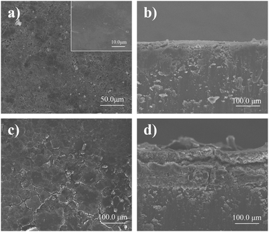 | ||
| Fig. 7 SEM images of the LFPP-Li anode (a, top view; b, side view) and the polished Li (c, top view; d, side view) anode after cycling in Li//LiFePO4 cells for 500 cycles at 0.5C. | ||
The advantages of LFPP SEI layer becomes much more obvious when subjecting to long cycle performance measurements at a rate of 1C, as shown in Fig. 6b, and at a rate of 0.5C in Fig. 6e. In Fig. 6b, the long cycle performance at 1C was performed from the 61st cycle to the 450th cycle. As listed in Table 1, the capacity retention and coulombic efficiency of the cell using an LFPP-Li anode is much higher than that using a polished Li anode. The cell using an LFPP 2%-Li anode exhibits the highest capacity retention of 75.8% and a high coulombic efficiency of 99.0% at 1C after 390 cycles. During the long cycle performance at 0.5C in Fig. 6e, the batteries using an LFPP 2%-Li anode and an LFPP 1%-Li anode exhibit the best performance with a very high coulombic efficiency of 100.0% and capacity retentions of 77.5% and 77.7% respectively.
The cyclic voltammogram (CV) measurement of Li LFPP 1%-Li//LFP was carried out from 2.5 V to 4.0 V at a scan rate of 0.1 mV s−1. The oxidation potential and reduction potential of the first and second cycles are 3.86 V/3.13 V and 3.74 V/3.11 V, respectively, indicating the decreased polarization voltage. This is attributed to the improvement of compatibility as demonstrated further in the following EIS tests. The EIS measurements were conducted from 100 kHz to 1 Hz at a voltage of 5 mV before and after CV measurements. As shown in Fig. 6f, the interface impedance (the diameter of the semicircle) becomes smaller after 5 cycles, owing to the improvement of compatibility among the Li metal, LFPP SEI layer, and liquid electrolyte. The battery performance and CV curves of LFPP-Li applied in Li//NCM full cells are shown in Fig. S2 (ESI†). Their cycle stability is inferior to that of Li//LFP batteries.
To further evaluate the effect of the LFPP SEI layer present on the lithium metal anode surface on battery performance, the Li//LiFePO4 cells with LPFP-Li and polished Li anodes were disassembled after 500 cycles, followed by the examination under a SEM. Fig. 7c and d show the top view and side view of the polished Li anode after cycling in Li//LiFePO4 cells for 100 cycles at 0.5C, depicting obvious cracks from the top view and numerous lithium dendrites and dead lithium from the cross-section. Compared with the polished Li anode, the LFPP-Li anode (Fig. 7a) presents a smooth top surface with very few defects. From the cross-section in Fig. 7b, it was found that there are almost no dead lithium and very few lithium dendrites, demonstrating the effective suppression of lithium dendrite formation on the LFPP SEI layer.
Conclusion
In summary, we report a novel artificial SEI layer, which exhibits high ionic conductivity and single-ion conductive characteristics. The LFPP SEI layer showed a very high ionic conductivity up to 0.0927 mS cm−1. Furthermore, its lithium ion transference number is 0.91, which is quite high near to unity. These characteristics can weaken or even eliminate the anion depletion–induced strong electric fields on the lithium anode to prevent the nucleation of lithium dendrites, finally suppressing the formation of lithium dendrites from the source. The SEI layer also shows very good electrochemical stability from 0 to 5.2 V. The symmetric cell with LFPP 1%-Li exhibits a very small over-potential at 0.038 V for over 1000 h at a current density of 0.5 mA cm−2 with a capacity of 1 mA h cm−2. The Li//LFP full cells using an LFPP 2%-Li anode give the most stable capacity with the highest capacity retention of 75.8% and an extra high coulombic efficiency of 99.0% at 1C after 390 cycles. During the long cycle performance at 0.5C, the batteries using LFPP 2%-Li and LFPP 1%-Li anodes exhibit the best performance with 100% coulombic efficiency on average and capacity retentions of 77.5% and 77.7%, respectively. Therefore, LFPP SEI layer is an outstanding artificial protective layer for the Li metal anode to achieve the objective of stability and dendrite growth suppression when applied in lithium metal batteries.Experimental section
Chemicals and materials
Super dry solvents including acetonitrile and N,N-dimethylformamide were purchased from JK Chemical and used without any pretreatment. 2-Dimethoxy-2-phenylacetophenone (DMPA) (Aladdin), sodium p-styrenesulfonate (Aladdin), and thionyl chloride were also used as-purchased. Super P (MTI Kejing), PVDF (Arkema), and LiFePO4 (MTI Kejing) were dried at 50 °C under high vacuum before use. All liquid reagents such as pentaerythritol tetraacrylate (PET4A, J&K) and pentaerythritol tetrakis (3-mercaptopropionate) (PETMP, Aldrich) were dried using 3 Å molecule sieves and stored in a glove box. Lithium[(4-styrenesulfonyl)(fluorosulfonyl)imide] (LiSFSI) was synthesized according to a procedure reported in our previous work and related studies.53Preparation process of LFPP-Li anodes
A precursor solution was first prepared with LiSFSI, PET4A, and PETMP using dimethyl carbonate (DMC, J&K Chemical, super dry) and DMPA as the solvent and initiator respectively. Then 70 μL precursor solution was dropped onto the top surface of a polished lithium metal foil. The polished lithium metal foil was obtained in two steps, namely, removal of the surface oxidation layer of the commercial lithium foil using a blade and rolling out using a glass rod. After thiol–ene click polymerization under 365 nm UV light for 30 min, the LFPP SEI layer took shape on the lithium foil. Although DMC is very easy to volatilize, LFPP-Li was completely dried under high vacuum at room temperature for 30 min to remove the residual solvent.Electrochemical measurements
An LFPP-coated stainless steel (LFPP-SS) electrode was prepared by the same method as that used for LFPP-Li preparation. Afterwards, symmetric coin cells were assembled by two LFPP-coated stainless steel round electrodes with a diameter of 15.5 mm, using a PP (Celgard 2500) membrane as the separator and 20.0 μL DMC/EC/EMC (vol% = 1![[thin space (1/6-em)]](https://www.rsc.org/images/entities/char_2009.gif) :
:![[thin space (1/6-em)]](https://www.rsc.org/images/entities/char_2009.gif) 1
1![[thin space (1/6-em)]](https://www.rsc.org/images/entities/char_2009.gif) :
:![[thin space (1/6-em)]](https://www.rsc.org/images/entities/char_2009.gif) 1) as the solvent. Electrochemical impedance spectroscopy (EIS) was performed in the symmetric coin cells using a Solartron 1255B frequency response analyzer from 0.1 MHz to 1 Hz at an amplitude of 5 mV at 25 °C. The ionic conductivity was calculated according to the following formula:
1) as the solvent. Electrochemical impedance spectroscopy (EIS) was performed in the symmetric coin cells using a Solartron 1255B frequency response analyzer from 0.1 MHz to 1 Hz at an amplitude of 5 mV at 25 °C. The ionic conductivity was calculated according to the following formula:| σ = lSEI+PP/(Rb × A) | (1) |
The electrochemical stability of the LFPP SEI layer was tested in a standard 2032 coin cell using an LFPP-SS electrode as the cathode and LFPP-Li as the anode, and a carbon cathode and LFPP-Li as the anode (Super P//LFPP-Li) with 1 M LiPF6/DMC![[thin space (1/6-em)]](https://www.rsc.org/images/entities/char_2009.gif) :
:![[thin space (1/6-em)]](https://www.rsc.org/images/entities/char_2009.gif) EC
EC![[thin space (1/6-em)]](https://www.rsc.org/images/entities/char_2009.gif) :
:![[thin space (1/6-em)]](https://www.rsc.org/images/entities/char_2009.gif) EMC (vol% = 1
EMC (vol% = 1![[thin space (1/6-em)]](https://www.rsc.org/images/entities/char_2009.gif) :
:![[thin space (1/6-em)]](https://www.rsc.org/images/entities/char_2009.gif) 1
1![[thin space (1/6-em)]](https://www.rsc.org/images/entities/char_2009.gif) :
:![[thin space (1/6-em)]](https://www.rsc.org/images/entities/char_2009.gif) 1) as the liquid electrolyte. A carbon cathode was made by a casting method with a weight ratio of Super P
1) as the liquid electrolyte. A carbon cathode was made by a casting method with a weight ratio of Super P![[thin space (1/6-em)]](https://www.rsc.org/images/entities/char_2009.gif) :
:![[thin space (1/6-em)]](https://www.rsc.org/images/entities/char_2009.gif) PVDF = 1
PVDF = 1![[thin space (1/6-em)]](https://www.rsc.org/images/entities/char_2009.gif) :
:![[thin space (1/6-em)]](https://www.rsc.org/images/entities/char_2009.gif) 1. Linear scanning voltammetry (LSV) was conducted from 0 to 6.0 V (vs. Li+/Li) at a scan speed of 1 mV s−1 at room temperature. Cyclic voltammogram (CV) was conducted from 2.5 V to 4.2 V at a scan speed of 1 mV s−1.
1. Linear scanning voltammetry (LSV) was conducted from 0 to 6.0 V (vs. Li+/Li) at a scan speed of 1 mV s−1 at room temperature. Cyclic voltammogram (CV) was conducted from 2.5 V to 4.2 V at a scan speed of 1 mV s−1.
The galvanostatic cycling performance of symmetric Li//Li cells with an LFPP-Li anode or a polished Li anode was performed at a current density of 0.5 mA cm−2 with a capacity of 1 mA h cm−2.
An LiFePO4 (LFP) cathode was obtained by a casting method in a weight ratio of LFP![[thin space (1/6-em)]](https://www.rsc.org/images/entities/char_2009.gif) :
:![[thin space (1/6-em)]](https://www.rsc.org/images/entities/char_2009.gif) Super P
Super P![[thin space (1/6-em)]](https://www.rsc.org/images/entities/char_2009.gif) :
:![[thin space (1/6-em)]](https://www.rsc.org/images/entities/char_2009.gif) PVDF of 8
PVDF of 8![[thin space (1/6-em)]](https://www.rsc.org/images/entities/char_2009.gif) :
:![[thin space (1/6-em)]](https://www.rsc.org/images/entities/char_2009.gif) 1
1![[thin space (1/6-em)]](https://www.rsc.org/images/entities/char_2009.gif) :
:![[thin space (1/6-em)]](https://www.rsc.org/images/entities/char_2009.gif) 1. The loading density of LFP is about 1.8 mg cm−2. Cathode circles (Φ = 12 mm) were obtained using a cutting machine. The Li/LFP cells were assembled in standard CR2025 coin cells with LPFF-Li as the anode in a glove box. As control groups, batteries using a polished bare Li metal as the anode were assembled. Battery performance tests were performed in a voltage range between 2.5 V and 4.0 V at 28 °C. The Li/LFP cells using an LFPP-Li anode and a polished Li anode after 100 cycles were taken apart, and then the electrodes were washed with DMC for SEM analysis and XPS analysis.
1. The loading density of LFP is about 1.8 mg cm−2. Cathode circles (Φ = 12 mm) were obtained using a cutting machine. The Li/LFP cells were assembled in standard CR2025 coin cells with LPFF-Li as the anode in a glove box. As control groups, batteries using a polished bare Li metal as the anode were assembled. Battery performance tests were performed in a voltage range between 2.5 V and 4.0 V at 28 °C. The Li/LFP cells using an LFPP-Li anode and a polished Li anode after 100 cycles were taken apart, and then the electrodes were washed with DMC for SEM analysis and XPS analysis.
A lithium nickel cobalt manganese oxide (NCM) cathode was fabricated by a casting method in a weight ratio of NCM 523![[thin space (1/6-em)]](https://www.rsc.org/images/entities/char_2009.gif) :
:![[thin space (1/6-em)]](https://www.rsc.org/images/entities/char_2009.gif) Super P
Super P![[thin space (1/6-em)]](https://www.rsc.org/images/entities/char_2009.gif) :
:![[thin space (1/6-em)]](https://www.rsc.org/images/entities/char_2009.gif) PVDF of 8
PVDF of 8![[thin space (1/6-em)]](https://www.rsc.org/images/entities/char_2009.gif) :
:![[thin space (1/6-em)]](https://www.rsc.org/images/entities/char_2009.gif) 1
1![[thin space (1/6-em)]](https://www.rsc.org/images/entities/char_2009.gif) :
:![[thin space (1/6-em)]](https://www.rsc.org/images/entities/char_2009.gif) 1. The loading density of NCM is 3.6 mg cm−2. Then Li/NCM cells were assembled in standard CR2025 coin cells with LFPP-Li as the anode using 1 M LiPF6/DMC
1. The loading density of NCM is 3.6 mg cm−2. Then Li/NCM cells were assembled in standard CR2025 coin cells with LFPP-Li as the anode using 1 M LiPF6/DMC![[thin space (1/6-em)]](https://www.rsc.org/images/entities/char_2009.gif) :
:![[thin space (1/6-em)]](https://www.rsc.org/images/entities/char_2009.gif) EC
EC![[thin space (1/6-em)]](https://www.rsc.org/images/entities/char_2009.gif) :
:![[thin space (1/6-em)]](https://www.rsc.org/images/entities/char_2009.gif) EMC (vol% = 1
EMC (vol% = 1![[thin space (1/6-em)]](https://www.rsc.org/images/entities/char_2009.gif) :
:![[thin space (1/6-em)]](https://www.rsc.org/images/entities/char_2009.gif) 1
1![[thin space (1/6-em)]](https://www.rsc.org/images/entities/char_2009.gif) :
:![[thin space (1/6-em)]](https://www.rsc.org/images/entities/char_2009.gif) 1) as the liquid electrolyte in a glove box. Battery performance tests were performed in a voltage range between 3.0 V and 4.5 V at 28 °C.
1) as the liquid electrolyte in a glove box. Battery performance tests were performed in a voltage range between 3.0 V and 4.5 V at 28 °C.
Cyclic voltammogram (CV) measurements of Li/LFP cells with an LFPP-Li anode or a bare-Li anode were operated in a voltage range between 2.5 V and 4.0 V at a scan speed of 0.1 mV s−1 at room temperature. Cyclic voltammogram (CV) measurements of Li/NCM cells were conducted from 3.0 V to 4.7 V at a scan speed of 0.1 mV s−1 at room temperature.
Conflicts of interest
There are no conflicts to declare.Acknowledgements
This work was supported by the Link Project of the National Natural Science Foundation of China and Guangdong Province (Grant No. U1301244); the National Key Research and Development Program (2018YFA0702002, 2019YFA0705701); the National Key Research and Development Program (Japan-China Joint Research Program) (2017YFE9127900); National Natural Science Foundation of China (51573215, 21506260 and 21706294); Natural Science Foundation of Guangdong Province (2020A151501445); Guangdong Province Sci & Tech Bureau (Grant No. 2017B090901003); Guangzhou Scientific and Technological Planning Project (Grant No. 201904010271, 201804020025, 201707010424); China Postdoctoral Science Foundation (Grant No. 2019M663231); the Fundamental Research Funds for the Central Universities (Grant No. 17lgjc37, 18lgpy32, 19lgpy07).Notes and references
- J. B. Goodenough and K.-S. Park, J. Am. Chem. Soc., 2013, 135, 1167–1176 CrossRef CAS PubMed.
- S. Huang, R. Guan, S. Wang, M. Xiao, D. Han, L. Sun and Y. J. Meng, Prog. Polym. Sci., 2019, 89, 19–60 CrossRef CAS.
- J. M. Tarascon and M. Armand, Nature, 2001, 414, 359–367 CrossRef CAS PubMed.
- R. Liu, Z. Wu, P. He, H. Fan, Z. Huang, L. Zhang, X. Chang, H. Liu, C.-A. Wang and Y. Li, J. Materiomics, 2019, 5, 185–194 CrossRef.
- Z.-J. Zheng, Q. Su, Q. Zhang, X.-C. Hu, Y.-X. Yin, R. Wen, H. Ye, Z.-B. Wang and Y.-G. Guo, Nano Energy, 2019, 64, 103910 CrossRef CAS.
- Y. Luo, L. Guo, M. Xiao, S. Wang, S. Ren, D. Han and Y. Meng, J. Mater. Chem. A, 2020, 8, 4629–4646 RSC.
- W. Xu, J. Wang, F. Ding, X. Chen, E. Nasybulin, Y. Zhang and J.-G. Zhang, Energy Environ. Sci., 2014, 7, 513–537 RSC.
- N. Wu, Y.-R. Shi, T. Jia, X.-N. Du, Y.-X. Yin, S. Xin and Y.-G. Guo, ACS Appl. Mater. Interfaces, 2019, 11, 43200–43205 CrossRef CAS PubMed.
- Y. Lu, Z. Tu and L. A. Archer, Nat. Mater., 2014, 13, 961–969 CrossRef CAS PubMed.
- X.-B. Cheng, C. Yan, H.-J. Peng, J.-Q. Huang, S.-T. Yang and Q. Zhang, Energy Storage Mater., 2018, 10, 199–205 CrossRef.
- Y. Zhong, Y. Chen, Y. Cheng, Q. Fan, H. Zhao, H. Shao, Y. Lai, Z. Shi, X. Ke and Z. Guo, ACS Appl. Mater. Interfaces, 2019, 11, 37726–37731 CrossRef CAS PubMed.
- K. Deng, S. Wang, S. Ren, D. Han, M. Xiao and Y. Meng, J. Power Sources, 2017, 360, 98–105 CrossRef CAS.
- W. Lee, C. K. Lyon, J. H. Seo, R. Lopez-Hallman, Y. Leng, C. Y. Wang, M. A. Hickner, C. A. Randall and E. D. Gomez, Adv. Funct. Mater., 2019, 29, 1807872 CrossRef.
- J. Fu, P. Yu, N. Zhang, G. Ren, S. Zheng, W. Huang, X. Long, H. Li and X. Liu, Energy Environ. Sci., 2019, 12, 1404–1412 RSC.
- L. Long, S. Wang, M. Xiao and Y. Meng, Polymer electrolytes for lithium polymer batteries, J. Mater. Chem. A, 2016, 4, 10038–10069 RSC.
- X. Guan, Q. Wu, X. Zhang, X. Guo, C. Li and J. Xu, Chem. Eng. J., 2020, 382, 122935 CrossRef.
- D. Lin, Y. Liu, Z. Liang, H.-W. Lee, J. Sun, H. Wang, K. Yan, J. Xie and Y. Cui, Nat. Nanotechnol., 2016, 11, 626–632 CrossRef CAS PubMed.
- D. Chen, S. Huang, L. Zhong, S. Wang, M. Xiao, D. Han and Y. J. A. F. M. Meng, In Situ Preparation of Thin and Rigid COF Film on Li Anode as Artificial Solid Electrolyte Interphase Layer Resisting Li Dendrite Puncture, Adv. Funct. Mater., 2019, 7, 1907717 Search PubMed.
- R. Pathak, K. Chen, A. Gurung, K. M. Reza, B. Bahrami, J. Pokharel, A. Baniya, W. He, F. Wu and Y. Zhou, Nat. Commun., 2020, 11, 1–10 Search PubMed.
- S. Heng, X. Shan, W. Wang, Y. Wang, G. Zhu, Q. Qu and H. Zheng, Carbon, 2020, 159, 390–400 CrossRef CAS.
- L. Fan, Z. Guo, Y. Zhang, X. Wu, C. Zhao, X. Sun, G. Yang, Y. Feng and N. Zhang, J. Mater. Chem. A, 2020, 8, 251–258 RSC.
- K. Deng, J. Qin, S. Wang, S. Ren, D. Han, M. Xiao and Y. Meng, Effective Suppression of Lithium Dendrite Growth Using a Flexible Single-Ion Conducting Polymer Electrolyte, Small, 2018, 14, 1801420 CrossRef PubMed.
- Q. Ai, D. Li, J. Guo, G. Hou, Q. Sun, Q. Sun, X. Xu, W. Zhai, L. Zhang and J. Feng, Adv. Mater. Interfaces, 2019, 6, 1901187 CrossRef CAS.
- H. Lee, X. Ren, C. Niu, L. Yu, M. H. Engelhard, I. Cho, M. H. Ryou, H. S. Jin, H. T. Kim and J. Liu, Adv. Funct. Mater., 2017, 27, 1704391 CrossRef.
- Y. S. Lee, J. H. Lee, J. A. Choi, W. Y. Yoon and D. W. Kim, Adv. Funct. Mater., 2013, 23, 1019–1027 CrossRef CAS.
- K.-L. Liu, C.-H. Chao, H.-C. Lee, C.-S. Tsao, J. Fang, N.-L. Wu and C.-Y. Chao, J. Power Sources, 2019, 419, 58–64 CrossRef CAS.
- X. Li, Y. Liu, Y. Pan, M. Wang, J. Chen, H. Xu, Y. Huang, W. M. Lau, A. Shan and J. J. Zheng, J. Mater. Chem. A, 2019, 7, 21349–21361 RSC.
- C. Li, S. Liu, C. Shi, G. Liang, Z. Lu, R. Fu and D. Wu, Nat. Commun., 2019, 10, 1–9 CrossRef PubMed.
- L. Shen, H. B. Wu, F. Liu, C. Zhang, S. Ma, Z. Le and Y. Lu, Nanoscale Horiz., 2019, 4, 705–711 RSC.
- R. Pan, R. Sun, Z. Wang, J. Lindh, K. Edström, M. Strømme and L. Nyholm, Nano Energy, 2019, 55, 316–326 CrossRef CAS.
- T. T. Zuo, X. W. Wu, C. P. Yang, Y. X. Yin, H. Ye, N. W. Li and Y. G. Guo, Adv. Mater., 2017, 29, 1700389 CrossRef PubMed.
- J. Xiang, Y. Zhao, L. Yuan, C. Chen, Y. Shen, F. Hu, Z. Hao, J. Liu, B. Xu and Y. Huang, Nano Energy, 2017, 42, 262–268 CrossRef CAS.
- X. Wang, Z. Pan, Y. Wu, X. Ding, X. Hong, G. Xu, M. Liu, Y. Zhang and W. Li, Nano Res., 2019, 12, 525–529 CrossRef CAS.
- Q. Dong, B. Hong, H. Fan, H. Jiang, K. Zhang and Y. Lai, ACS Appl. Mater. Interfaces, 2019, 12, 627–636 CrossRef PubMed.
- G. Wang, X. Xiong, P. Zou, X. Fu, Z. Lin, Y. Li, Y. Liu, C. Yang and M. Liu, Chem. Eng. J., 2019, 378, 122243 CrossRef CAS.
- Z. Zheng, Y. Zao, Q. Zhang, Y. Cheng, H. Chen, K. Zhang, M.-S. Wang and D. L. Peng, Chem. Eng. J., 2018, 347, 563–573 CrossRef CAS.
- K. Shen, Z. Wang, X. Bi, Y. Ying, D. Zhang, C. Jin, G. Hou, H. Cao, L. Wu and G. Zheng, Adv. Energy Mater., 2019, 9, 1900260 CrossRef.
- R. Xu, X. Q. Zhang, X. B. Cheng, H. J. Peng, C. Z. Zhao, C. Yan and J. Q. Huang, Adv. Funct. Mater., 2018, 28, 1705838 CrossRef.
- L. Wang, L. Zhang, Q. Wang, W. Li, B. Wu, W. Jia, Y. Wang, J. Li and H. Li, Energy Storage Mater., 2018, 10, 16–23 CrossRef.
- N. W. Li, Y. Shi, Y. X. Yin, X. X. Zeng, J. Y. Li, C. J. Li, L. J. Wan, R. Wen and Y. G. Guo, Angew. Chem., Int. Ed., 2018, 57, 1505–1509 CrossRef CAS PubMed.
- J. Luo, C. C. Fang and N. L. Wu, Adv. Energy Mater., 2018, 8, 1701482 CrossRef.
- R. Xu, Y. Xiao, R. Zhang, X. B. Cheng, C. Z. Zhao, X. Q. Zhang, C. Yan, Q. Zhang and J. Q. Huang, Adv. Mater., 2019, 31, 1808392 CrossRef PubMed.
- Q. Ai, D. Li, J. Guo, G. Hou, Q. Sun, Q. Sun, X. Xu, W. Zhai, L. Zhang and J. Feng, Adv. Mater. Interfaces, 2019, 6, 1901187 CrossRef CAS.
- K. Li, Y. Wang, W. Jia, S. Qu, Z. Yao, R. Cui, W. Zou, F. Zhou and J. Li, ACS Appl. Mater. Interfaces, 2019, 12, 2285–2292 CrossRef PubMed.
- M. Bai, K. Xie, B. Hong, K. Yuan, Z. Li, Z. Huang, C. Shen and Y. Lai, Solid State Ionics, 2019, 333, 101–104 CrossRef CAS.
- Z. T. Wondimkun, T. T. Beyene, M. A. Weret, N. A. Sahalie, C.-J. Huang, B. Thirumalraj, B. A. Jote, D. Wang, W.-N. Su and C.-H. Wang, J. Power Sources, 2020, 450, 227589 CrossRef CAS.
- D. Chen, S. Huang, L. Zhong, S. Wang, M. Xiao, D. Han and Y. Meng, In Situ Preparation of Thin and Rigid COF Film on Li Anode as Artificial Solid electrolyte interphase layer resisting li dendrite puncture, Adv. Funct. Mater., 2019, 7, 1907717 Search PubMed.
- J. Zhu, P. Li, X. Chen, D. Legut, Y. Fan, R. Zhang, Y. Lu, X. Cheng and Q. Zhang, Energy Storage Mater., 2019, 16, 426–433 CrossRef.
- M. D. Tikekar, L. A. Archer and D. L. Koch, Sci. Adv., 2016, 2, e1600320 CrossRef PubMed.
- Y. Zhong, L. Zhong, S. Wang, J. Qin, D. Han, S. Ren, M. Xiao, L. Sun and Y. Meng, J. Mater. Chem. A, 2019, 7, 24251–24261 RSC.
- X. Yang, M. Jiang, X. Gao, D. Bao, Q. Sun, N. Holmes, H. Duan, S. Mukherjee, K. Adair, C. Zhao, J. Liang, W. Li, J. Li, Y. Liu, H. Huang, L. Zhang, S. Lu, Q. Lu, R. Li, C. V. Singh and X. Sun, Determining the limiting factor of the electrochemical stability window for PEO-based solid polymer electrolytes: main chain or terminal –OH group?, Energy Environ. Sci., 2020, 13, 1318–1325 RSC.
- J. Bae, Y. Qian, Y. Li, X. Zhou, J. B. Goodenough and G. E. Yu, Energy Environ. Sci., 2019, 12, 3319–3327 RSC.
- Q. Ma, H. Zhang, C. Zhou, L. Zheng, P. Cheng, J. Nie, W. Feng, Y. S. Hu, H. Li and X. Huang, Angew. Chem., Int. Ed., 2016, 55, 2521–2525 CrossRef CAS PubMed.
- Q. Ma, X. X. Zeng, J. Yue, Y. X. Yin, T. T. Zuo, J. Y. Liang, Q. Deng, X. W. Wu and Y. G. Guo, Adv. Energy Mater., 2019, 9, 1803854 CrossRef.
Footnote |
| † Electronic supplementary information (ESI) available. See DOI: 10.1039/d0ma00260g |
| This journal is © The Royal Society of Chemistry 2020 |

