 Open Access Article
Universal solid-state oxygen redox in antifluorite lithium oxides via transition metal doping†
Hiroaki
Kobayashi
 *a,
Tetsuya
Makimoto
b,
Yoshiyuki
Ogasawara
b,
Kosuke
Harada
b,
Masanobu
Nakayama
 c,
Mitsuhiro
Hibino
b,
Tetsuichi
Kudo
b,
Noritaka
Mizuno
b and
Kazuya
Yamaguchi
 b
b
aInstitute of Multidisciplinary Research for Advanced Materials, Tohoku University, 2-1-1 Katahira, Aoba-ku, Sendai, Miyagi 980-8577, Japan. E-mail: h.kobayashi@tohoku.ac.jp
bDepartment of Applied Chemistry, School of Engineering, The University of Tokyo, 7-3-1 Hongo, Bunkyo-ku, Tokyo, 113-8656, Japan
cDepartment of Advanced Ceramics, Nagoya Institute of Technology, Gokiso, Showa, Nagoya, Aichi 466-8555, Japan
First published on 14th July 2020
Abstract
Solid-state oxygen redox can potentially be used in high-capacity cathode materials of lithium-ion batteries. This study demonstrates a reversible solid-state oxygen redox in antifluorite lithium oxide via doping of Ni. Ni-Doping of Li2O enables the reversible redox reaction of O2−/O22− in addition to the transition metal redox, with a reversible capacity of 270 mA h g−1. The O K-edge X-ray absorption spectroscopy reveals that the solid-state oxygen redox reaction is universal in transition metal dopants, which are probably activated by the 2p electron holes in O that are formed via hybridization with d orbitals of the transition metal. Considering the cathode performances and earth abundance of dopant transition metals, Ni-doping of Li2O effectively leads to the development of high-capacity cathode materials.
Introduction
High-performance lithium-ion batteries (LIBs) are attractive choices for stationary storage applications because of their high energy density and specific capacity. Enhancing the energy densities of the cathodes in LIBs by utilizing the redox reactions of oxide ions in cathode materials has recently attracted extensive attention.1–5 For instance, Li-rich layered rocksalts (Li2MnO3,6–12 Li2RuO3,13–15 Li2IrO3,16–18 and their solid solutions with LiTMO2 (TM: transition metal)19–23), disordered rocksalts (Li3NbO4–LiTMO2,24 Li2TiO3–LiTMO2,25 and Li4Mn2O526,27), and antifluorites (Li5FeO4,28–37 Li6CoO4,28,38 and Li5AlO439,40) facilitate an increase in capacity by using partial oxygen redox along with transition metal redox. Among them, antifluorite Li2O exhibits the highest possible theoretical capacity of 897 mA h g−1, which is based on the solid-state oxygen redox reaction given by| 2Li2O ⇄ Li2O2 + 2Li+ + 2e− | (1) |
Li2O and Li2O2 demonstrate low electrochemical activities and poor electric conductivities. However, metal/metal oxide compositions (i.e., Co3O4, Ru, and Ir) can activate Li2O to enable the forward reaction.41–45 These composite cathodes exhibit high capacities and great cyclability; however, they require expensive metal elements with concentrations of more than 20 wt%. Contrarily, metal doping of Li2O effectively utilizes oxygen redox. Previous studies have reported that 5–10 mol% TM consisting of Fe,46 Co,47–52 Cu,53 Rh,47 and Ir47 are substitutionally introduced to the cationic site of Li2O. The transition metal-doped Li2O (TMDL) cathodes exhibit a reversible solid-state oxygen redox reaction, along with a TM dopant redox reaction. When considering the doped TM and assuming that the TM and all oxygen are involved in the redox reaction, the theoretical capacity of TMDL (5– 10 mol%) is 800–880 mA h g−1. Therefore, TMDL is a promising high-capacity cathode material.
The main role of doped TM is to enhance the conductivity and/or catalytic activity of oxygen because the solid-state oxygen redox reaction does not contain TM. Therefore, the solid-state oxygen redox reaction of TMDL should be independent of dopant elements. Herein, we show a unique cathode material of TMDL doped with Ni and demonstrate a universal solid-state oxygen redox reaction of TMDL.
Results and discussion
Effect of Ni-doping to lithium oxide
Ni-Doping of Li2O was conducted using a mechanochemical treatment. The optimized cathode material was prepared using LiNiO2 as a Ni-dopant source with an atomic ratio of Ni/(Li + Ni) = 8% (see Section S1, ESI† for details).
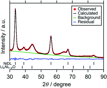
Fig. 1 shows the X-ray powder diffraction (XRD) pattern of the sample. Broad peaks were attributed to a Li2O-based antifluorite and LiNiO2-based phase. The scanning electron microscopy (SEM) images show that aggregation of particles occurs and the particle size is ranged from 1 to 10 μm (see Fig. S3, ESI†). The Ni K-edge XAS analyses show that Ni-doping of the cation site in the Li2O structure occurs to form Ni-doped Li2O (NiDL, see Section S3, ESI† for details). However, in the Li2O-based phase, only 1.8% of the cation site is substituted with Ni according to the Rietveld refinement (Fig. 1 and Table 1); less Ni-doping occurs compared with Fe-, Co-, or Cu-doping to Li2O, where 6–8% of the Li2O cation site is substituted by Fe, Co, and Cu.46,49,53 This can, probably occur because Ni prefers octahedral coordination over tetrahedral coordination.54 The undoped LiNiO2 remains as the LiNiO2-based phase; in the phase, the main peak of the pristine LiNiO2 at around 18° almost disappears, while broad peaks at 38°, 45°, and 64° are observed (see Fig. S2a, ESI†). These peaks are attributable to 111, 200, and 220 reflections of cubic rocksalt LixNi1−xO (x < 0.5, Fm![[3 with combining macron]](https://www.rsc.org/images/entities/char_0033_0304.gif) m, PDF#01-081-0095), respectively. Since the hexagonal layered rocksalt LiNiO2 transforms to cubic cation-disordered rocksalt LixNi1−xO by the mechanochemical treatment (see the previous literature55 and Section S4, ESI†), the LiNiO2-based phase is attributed to the cubic cation-disordered rocksalt LixNi1−xO. As a result, the sample is composed of 0.87(1) (Li0.947(9)Ni0.018(3))2O + 0.13(1) Li0.458(18)Ni0.541(18)O.
m, PDF#01-081-0095), respectively. Since the hexagonal layered rocksalt LiNiO2 transforms to cubic cation-disordered rocksalt LixNi1−xO by the mechanochemical treatment (see the previous literature55 and Section S4, ESI†), the LiNiO2-based phase is attributed to the cubic cation-disordered rocksalt LixNi1−xO. As a result, the sample is composed of 0.87(1) (Li0.947(9)Ni0.018(3))2O + 0.13(1) Li0.458(18)Ni0.541(18)O.
| Phase | Space group | Lattice parameters (Å) | Atom | Site | Occupancy (g) | Fraction (mol%) |
|---|---|---|---|---|---|---|
| a R wp = 3.36%, Rp = 2.64%, Re = 2.34%, S = 1.43. | ||||||
| NiDL |
Fm![[3 with combining macron]](https://www.rsc.org/images/entities/char_0033_0304.gif) m m |
a = 4.6136(5) | Li | 8c | g = 0.947(9) | 87(1) |
| Ni | 8c | g = 0.018(3) | ||||
| O | 4a | |||||
| LixNi1−xO |
Fm![[3 with combining macron]](https://www.rsc.org/images/entities/char_0033_0304.gif) m m |
a = 4.097(5) | Li | 4a | g = 0.458(18) | 13(1) |
| Ni | 4a | g = 0.541(18) | ||||
| O | 4b | |||||
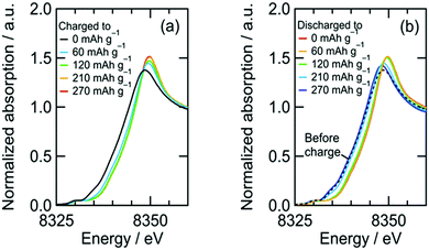
Cathode reactions of NiDL was investigated. Fig. 2 shows voltage curves during the first charge/discharge cycle and the amount of evolved gas during the first charge. The charge curve is divided into two regions: a slope at 2.5–3.2 V and a plateau at 3.2 V. The former slope region showed that the Ni K-edge energy shifted to higher energy, which indicated the oxidation of Ni (Fig. 3a). On the other hand, little change in the edge energy was observed at the following plateau region, suggesting that oxidation other than Ni occurred. The gas evolution occurs over 250 mA h g−1 when charging; herein, a ¼ gas evolution rate is achieved for every transferred electron, which indicates the occurrence of the following O2 evolution reaction:
| 2O2− → O2 + 4e− | (2) |
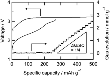 | ||
| Fig. 2 Voltage curves and the amount of evolved gas of NiDL cathode. M: amount of evolved gas, Q: amount of transferred electrons. | ||
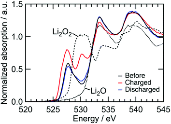
We confirmed an evolved gas as oxygen by in situ gas analysis using quadrupole mass spectrometer with TMDL cathode using Co as a dopant (see Section S5, ESI†). Since structural and electrochemical properties are quite similar among TMDLs as shown below, the evolved gas in Fig. 2 is probably oxygen. The irreversibility of this reaction causes the specific capacity of NiDL to be restricted to less than ca. 250 mA h g−1. However, by regulating the charge capacity to achieve a value of 270 mA h g−1, the subsequent discharge reaction occurred reversibly. Note that in the cathode material, the fraction of the LixNi1−xO phase is 19 wt%. However, LixNi1−xO exhibits no redox plateaus, and its reversible capacity is 46 mA h g−1 (see Section S4, ESI†); this value corresponds to only 8.7 mA h g−1 in the cathode material and the reversible capacity of 270 mA h g−1 is due to NiDL. The discharge curve was divided into two regions: slopes at 3.1–2.8 V and 2.8–1.5 V. A slight shift in the Ni K-edge energy was observed at the former slope region, while a shift to lower energy was observed at the latter slope region (Fig. 3b). This indicates that the reduction of Ni occurs in the low voltage region. The redox reaction at the higher voltage was verified by investigating the O K-edge X-ray absorption spectroscopy (XAS) analysis (Fig. 4). The O K-edge XANES spectra showed a peak at approximately 527.7 eV, which was not observed in Li2O. This peak derived from O 2p electron holes (![[O with combining low line]](https://www.rsc.org/images/entities/char_004f_0332.gif) ) formed by hybridization with Ni 3d orbitals. The strong hybridization of Ni and O is supported by first-principles band calculations (see Section S6, ESI†). In addition, its peak intensity increased after charging and decreased after discharging. This reversible change is caused by the Ni redox. Note that the Ni redox is cationic redox and formally Ni3+/Ni4+, but the redox should be appropriately expressed as the formation/annihilation of
) formed by hybridization with Ni 3d orbitals. The strong hybridization of Ni and O is supported by first-principles band calculations (see Section S6, ESI†). In addition, its peak intensity increased after charging and decreased after discharging. This reversible change is caused by the Ni redox. Note that the Ni redox is cationic redox and formally Ni3+/Ni4+, but the redox should be appropriately expressed as the formation/annihilation of ![[O with combining low line]](https://www.rsc.org/images/entities/char_004f_0332.gif) due to the strong hybridization of Ni 3d and O 2p orbitals.56 On the other hand, a peak at 530.2 eV appeared and disappeared after being charged and discharged, respectively. This was caused by the formation/annihilation of σ*(O–O) orbital. Therefore, the redox reaction at a higher voltage derives from the O2−/O22− redox reaction. The XAS analyses indicated that NiDL shows reversible cationic (formally Ni3+/Ni4+) and anionic (O2−/O22−) redox reactions.
due to the strong hybridization of Ni 3d and O 2p orbitals.56 On the other hand, a peak at 530.2 eV appeared and disappeared after being charged and discharged, respectively. This was caused by the formation/annihilation of σ*(O–O) orbital. Therefore, the redox reaction at a higher voltage derives from the O2−/O22− redox reaction. The XAS analyses indicated that NiDL shows reversible cationic (formally Ni3+/Ni4+) and anionic (O2−/O22−) redox reactions.
Universal solid-state oxygen redox with transition metal-doped lithium oxide
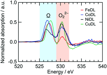
Redox reactions of TMDL are similar between Fe-, Co-, Ni-, and Cu-doped Li2O (i.e., FeDL, CoDL, NiDL, and CuDL, respectively). Fig. 5 shows the difference in spectra of O K-edge XANES before and after the charging process. O K-edge XANES spectra of FeDL, CoDL, and CuDL during the first charge/discharge cycle are shown in Fig. S10 (ESI†). Two peaks are observed for each cathode at 525–529 eV and 529–535 eV, respectively. The former peaks are caused by the formation of![[O with combining low line]](https://www.rsc.org/images/entities/char_004f_0332.gif) in the O 2p–TM d hybridized orbital. The peak positions differ in the dopant TM because the hybridized orbital has different energy levels. The latter peaks are caused by the formation of O22− species. The latter peak positions are approximately similar (530.2 eV) regardless of the dopant TM. This analysis suggests that the doped TM probably does not contribute to the O2−/O22− redox; however, it contributes to the preceding
in the O 2p–TM d hybridized orbital. The peak positions differ in the dopant TM because the hybridized orbital has different energy levels. The latter peaks are caused by the formation of O22− species. The latter peak positions are approximately similar (530.2 eV) regardless of the dopant TM. This analysis suggests that the doped TM probably does not contribute to the O2−/O22− redox; however, it contributes to the preceding ![[O with combining low line]](https://www.rsc.org/images/entities/char_004f_0332.gif) formation, which could catalyse the O22− formation.
formation, which could catalyse the O22− formation.
These behaviours are indicated by the voltage curves (Fig. 6a). Diverse curves are observed in the region where the voltage increases (i.e., ![[O with combining low line]](https://www.rsc.org/images/entities/char_004f_0332.gif) formation reaction) for different TMs, but similar 3.2 V plateaus (i.e., O22− formation reaction) were observed. The resulting discharge shows that the slopes at 3.1–2.8 V (i.e., O22− annihilation reaction) are approximately similar, except for the plateau length. This similarity substantiates the universal O2−/O22− redox characteristic of TMDLs.
formation reaction) for different TMs, but similar 3.2 V plateaus (i.e., O22− formation reaction) were observed. The resulting discharge shows that the slopes at 3.1–2.8 V (i.e., O22− annihilation reaction) are approximately similar, except for the plateau length. This similarity substantiates the universal O2−/O22− redox characteristic of TMDLs.
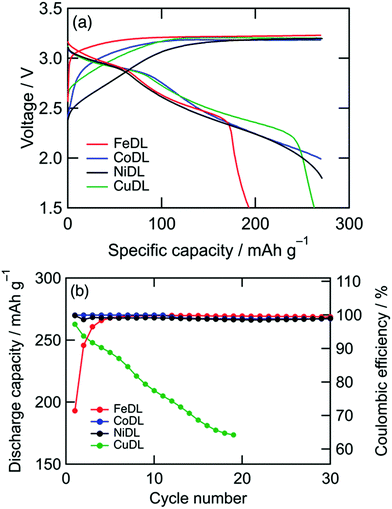 | ||
| Fig. 6 (a) Voltage curves of TMDL cathodes during first cycle and (b) capacity retentions. Charge capacity was regulated to 270 mA h g−1. The plotted data correspond with both axes. | ||
However, cathode performances, such as cyclability, varied among TMDLs (Fig. 6b). CoDL and NiDL exhibited moderate cyclability with a specific capacity of 270 mA h g−1. Whereas, FeDL showed a capacity loss during the primary cycles and a high coulombic reversible charge/discharge efficiency after ten cycles. This initial capacity loss in FeDL is probably caused by the difficulty with ![[O with combining low line]](https://www.rsc.org/images/entities/char_004f_0332.gif) annihilation (i.e., reduction of Fe4+ to Fe3+).46 In the case of CuDL, the discharge capacity gradually decreased during the charge/discharge cycles because of the decomposition of CuDL. This decomposition is mainly caused by Jahn–Teller distortion of Cu2+; tetrahedrally coordinated Cu in the Li2O structure can transform into Li2CuO2 with a square planar coordination via charge/discharge repetition.53 Considering cathode performances and the earth-abundance of dopant metals, NiDL is a promising cathode material. FeDL and CuDL can also be promising materials because of their earth abundance; however, this is possible only if cycle performances are improved. Recently, the cyclability of CuDL has been improved using fluorine doping.57 Doping other elements such as fluorine in cationic and anionic sites potentially can enhance the cathode performances of TMDLs. In addition, the surface modification of CoDL by vinylene carbonate or fluoroethylene carbonate shows excellent capacity improvement from 270 to 450 mA h g−1 while retaining its cyclability.50–52 Since TMDLs are basic and reactive with the electrolyte to decompose, such surface modification is also effective for enhancement of cathode performances.
annihilation (i.e., reduction of Fe4+ to Fe3+).46 In the case of CuDL, the discharge capacity gradually decreased during the charge/discharge cycles because of the decomposition of CuDL. This decomposition is mainly caused by Jahn–Teller distortion of Cu2+; tetrahedrally coordinated Cu in the Li2O structure can transform into Li2CuO2 with a square planar coordination via charge/discharge repetition.53 Considering cathode performances and the earth-abundance of dopant metals, NiDL is a promising cathode material. FeDL and CuDL can also be promising materials because of their earth abundance; however, this is possible only if cycle performances are improved. Recently, the cyclability of CuDL has been improved using fluorine doping.57 Doping other elements such as fluorine in cationic and anionic sites potentially can enhance the cathode performances of TMDLs. In addition, the surface modification of CoDL by vinylene carbonate or fluoroethylene carbonate shows excellent capacity improvement from 270 to 450 mA h g−1 while retaining its cyclability.50–52 Since TMDLs are basic and reactive with the electrolyte to decompose, such surface modification is also effective for enhancement of cathode performances.
Conclusions
This study achieved a reversible solid-state oxygen redox in Li2O via the doping of transition metals such as Ni. The resulting reaction is universal for transition metal dopants. This reversible solid-state oxygen redox is probably activated by O 2p electron holes that are formed through hybridization with d orbitals of transition metals. However, cathode performances are observed to vary among different transition metals. Ni-Doping shows a significant promise for high-capacity cathode materials when considering the cathode performances and earth abundance of Ni.Experimental section
The raw materials and as-obtained samples were handled in an Ar-filled glove box.Synthesis
Powders of Li2O (Kojundo Chemical Laboratory Co., Ltd) and a transition metal (TM) source material were placed into a zirconia milling pot with yttria stabilized zirconia (YSZ) milling balls (3 mm diameter), and then pulverized using a planetary ball mill (Pulverisette 7, Fritsch) at 600 rpm for 50 h. As the TM source materials, LiNiO2 (FUJIFILM Wako Pure Chemical Corp.), NiO (FUJIFILM Wako Pure Chemical Corp.), LiFeO2 (FUJIFILM Wako Pure Chemical Corp.), LiCoO2 (Strem Chemicals, Inc.), and CuO (Kanto Chemical Co., Inc.) were used. The atomic ratio of TM/(Li + TM) was set to 10, 9, and 9% for Fe-, Co-, and Cu-doped Li2O, respectively, with reference to the previous reports.46,49,53Characterization
Powder X-ray diffraction (XRD) patterns were recorded on a RIGAKU SmartLab system using monochromatized Cu-Kα1 radiation. The sample was mounted on a gas-tight holder with a Be window under Ar. The Rietveld analysis was conducted using RIETAN-FP program.58 Ni K-edge X-ray absorption near-edge structure (XANES) measurements were conducted using the transmission method at the BL-9C beamline of the Photon Factory in High Energy Accelerator Research Organization. Samples were sealed in an Al-laminated packaging film and attached to a sample holder. O K-edge XANES measurements were conducted using the fluorescence yield method at the BL-7A beamline. A sample holder was transferred to vacuum chambers using a transfer vessel filled with Ar. Ni K-edge and O K-edge XANES spectra were calibrated using Ni foil and Au foil, respectively, and analyzed using the Athena program.59 Scanning electron microscopy (SEM) images were obtained using Hitachi S-4700.Electrochemical measurements
Samples were mixed with acetylene black (AB, Denka Co., Ltd) and polytetrafluoroethylene (Dupont-Mitsui Fluorochemicals) in a weight ratio of 45/50/5 and pressed on an Al mesh current collector to serve as the cathode. In order to elucidate the charge and discharge characteristics of the active material, the cathode contained sufficiently large amount of acetylene black for enough conductivity. The typical mass of active materials per area in the electrode was 5 mg cm−2. For electrochemical tests, 2032-type coin cells were assembled with a Li metal foil as the anode, a glass filter (GA-55, ADVANTEC) as the separator, and 1 M LiBF4/ethylene carbonate–diethyl carbonate (1![[thin space (1/6-em)]](https://www.rsc.org/images/entities/char_2009.gif) :
:![[thin space (1/6-em)]](https://www.rsc.org/images/entities/char_2009.gif) 1 by volume, Kishida Chemical) as the electrolyte. Charge/discharge tests were carried out at a constant current of 22.5 mA g−1 at 25 °C. Gas evolution in a cell was confirmed by monitoring inner pressure change using a pressure gauge connected to the cell by a stainless steel tube and Swagelok™ fittings.
1 by volume, Kishida Chemical) as the electrolyte. Charge/discharge tests were carried out at a constant current of 22.5 mA g−1 at 25 °C. Gas evolution in a cell was confirmed by monitoring inner pressure change using a pressure gauge connected to the cell by a stainless steel tube and Swagelok™ fittings.
Conflicts of interest
There are no conflicts to declare.Acknowledgements
This work was financially supported by JSPS KAKENHI Grant 19K15668, 15K18326, 17H03530 and 15H05797, JST ALCA-SPRING Grant Number JPMJAL1301, “Five-star Alliance,” and Ensemble Grant for Young Researchers in Tohoku University Research Institutes.References
- A. Grimaud, W. T. Hong, Y. Shao-Horn and J.-M. Tarascon, Nat. Mater., 2016, 15, 121 CrossRef CAS PubMed.
- M. Li, T. Liu, X. Bi, Z. Chen, K. Amine, C. Zhong and J. Lu, Chem. Soc. Rev., 2020, 49, 1688–1705 RSC.
- M. Okubo and A. Yamada, ACS Appl. Mater. Interfaces, 2017, 9, 36463–36472 CrossRef CAS PubMed.
- B. Li and D. Xia, Adv. Mater., 2017, 29, 1701054 CrossRef PubMed.
- N. Yabuuchi, Chem. Lett., 2017, 46, 412–422 CrossRef CAS.
- P. Kalyani, S. Chitra, T. Mohan and S. Gopukumar, J. Power Sources, 1999, 80, 103–106 CrossRef CAS.
- A. D. Robertson and P. G. Bruce, Chem. Mater., 2003, 15, 1984–1992 CrossRef CAS.
- M. Oishi, K. Yamanaka, I. Watanabe, K. Shimoda, T. Matsunaga, H. Arai, Y. Ukyo, Y. Uchimoto, Z. Ogumi and T. Ohta, J. Mater. Chem. A, 2016, 4, 9293–9302 RSC.
- J. Rana, M. Stan, R. Kloepsch, J. Li, G. Schumacher, E. Welter, I. Zizak, J. Banhart and M. Winter, Adv. Energy Mater., 2014, 4, 1300998 CrossRef.
- P. Yan, L. Xiao, J. Zheng, Y. Zhou, Y. He, X. Zu, S. X. Mao, J. Xiao, F. Gao and J.-G. Zhang, Chem. Mater., 2015, 27, 975–982 CrossRef CAS.
- J. Rana, J. K. Papp, Z. Lebens-Higgins, M. Zuba, L. A. Kaufman, A. Goel, R. Schmuch, M. Winter, M. S. Whittingham and W. Yang, ACS Energy Lett., 2020, 5, 634–641 CrossRef CAS.
- N. Guerrini, L. Jin, J. G. Lozano, K. Luo, A. Sobkowiak, K. Tsuruta, F. Massel, L.-C. Duda, M. R. Roberts and P. G. Bruce, Chem. Mater., 2020, 32, 3733–3740 CrossRef CAS.
- M. Sathiya, G. Rousse, K. Ramesha, C. Laisa, H. Vezin, M. T. Sougrati, M.-L. Doublet, D. Foix, D. Gonbeau and W. Walker, Nat. Mater., 2013, 12, 827–835 CrossRef CAS PubMed.
- M. Saubanère, E. McCalla, J.-M. Tarascon and M.-L. Doublet, Energy Environ. Sci., 2016, 9, 984–991 RSC.
- M. Sathiya, K. Ramesha, G. Rousse, D. Foix, D. Gonbeau, A. Prakash, M. Doublet, K. Hemalatha and J.-M. Tarascon, Chem. Mater., 2013, 25, 1121–1131 CrossRef CAS.
- E. McCalla, A. M. Abakumov, M. Saubanère, D. Foix, E. J. Berg, G. Rousse, M.-L. Doublet, D. Gonbeau, P. Novák and G. Van Tendeloo, Science, 2015, 350, 1516–1521 CrossRef CAS PubMed.
- M. Sathiya, J.-B. Leriche, E. Salager, D. Gourier, J.-M. Tarascon and H. Vezin, Nat. Commun., 2015, 6, 1–7 Search PubMed.
- P. E. Pearce, A. J. Perez, G. Rousse, M. Saubanère, D. Batuk, D. Foix, E. McCalla, A. M. Abakumov, G. Van Tendeloo and M.-L. Doublet, Nat. Mater., 2017, 16, 580–586 CrossRef CAS PubMed.
- M. M. Thackeray, C. S. Johnson, J. T. Vaughey, N. Li and S. A. Hackney, J. Mater. Chem., 2005, 15, 2257–2267 RSC.
- S. Hy, H. Liu, M. Zhang, D. Qian, B.-J. Hwang and Y. S. Meng, Energy Environ. Sci., 2016, 9, 1931–1954 RSC.
- S. Zhao, K. Yan, J. Zhang, B. Sun and G. Wang, Angew. Chem. Int. Ed., 2020 DOI:10.1002/anie.202000262.
- P. Rozier and J. M. Tarascon, J. Electrochem. Soc., 2015, 162, A2490 CrossRef CAS.
- P. K. Nayak, E. M. Erickson, F. Schipper, T. R. Penki, N. Munichandraiah, P. Adelhelm, H. Sclar, F. Amalraj, B. Markovsky and D. Aurbach, Adv. Energy Mater., 2018, 8, 1702397 CrossRef.
- N. Yabuuchi, M. Takeuchi, M. Nakayama, H. Shiiba, M. Ogawa, K. Nakayama, T. Ohta, D. Endo, T. Ozaki and T. Inamasu, Proc. Natl. Acad. Sci. U. S. A., 2015, 112, 7650–7655 CrossRef CAS PubMed.
- N. Yabuuchi, M. Nakayama, M. Takeuchi, S. Komaba, Y. Hashimoto, T. Mukai, H. Shiiba, K. Sato, Y. Kobayashi and A. Nakao, Nat. Commun., 2016, 7, 1–10 Search PubMed.
- M. Freire, N. V. Kosova, C. Jordy, D. Chateigner, O. Lebedev, A. Maignan and V. Pralong, Nat. Mater., 2016, 15, 173–177 CrossRef CAS PubMed.
- Z. Yao, S. Kim, J. He, V. I. Hegde and C. Wolverton, Sci. Adv., 2018, 4, eaao6754 CrossRef PubMed.
- S. Narukawa, Y. Takeda, M. Nishijima, N. Imanishi, O. Yamamoto and M. Tabuchi, Solid State Ionics, 1999, 122, 59–64 CrossRef CAS.
- N. Imanishi, Y. Inoue, A. Hirano, M. Ueda, Y. Takeda, H. Sakaebe and M. Tabuchi, J. Power Sources, 2005, 146, 21–26 CrossRef CAS.
- A. Hirano, T. Matsumura, M. Ueda, N. Imanishi, Y. Takeda and M. Tabuchi, Solid State Ionics, 2005, 176, 2777–2782 CrossRef CAS.
- C. Johnson, S.-H. Kang, J. Vaughey, S. Pol, M. Balasubramanian and M. Thackeray, Chem. Mater., 2010, 22, 1263–1270 CrossRef CAS.
- K. Ding, L. Wang, J. Li, H. Jia and X. He, Int. J. Electrochem. Sci., 2011, 6, 6165–6176 CAS.
- K. Ding, L. Wang, J. Li, H. Jia and X. He, Int. J. Electrochem. Sci., 2011, 6, 2859–2868 CAS.
- K. Ding, L. Wang, J. Li, H. Jia and X. He, Int. J. Electrochem. Sci., 2012, 7, 1611 CAS.
- L. Liang, J. Luo, M. Chen, L. Wang, J. Li and X. He, Int. J. Electrochem. Sci., 2013, 8, 6393–6398 CAS.
- C. Zhan, Z. Yao, J. Lu, L. Ma, V. A. Maroni, L. Li, E. Lee, E. E. Alp, T. Wu and J. Wen, Nat. Energy, 2017, 2, 963–971 CrossRef CAS.
- L. Li, E. Lee, J. W. Freeland, T. T. Fister, M. M. Thackeray and M. K. Chan, J. Phys. Chem. Lett., 2019, 10, 806–812 CrossRef CAS PubMed.
- Z. Chen, Z. Zhang and J. Li, Phys. Chem. Chem. Phys., 2018, 20, 20363–20370 RSC.
- D. Okuda, H. Kobayashi and M. Ishikawa, Solid State Ionics, 2020, 353, 115374 CrossRef CAS.
- D. Okuda, H. Kobayashi and M. Ishikawa, ACS Omega, 2020, 5, 16912–16918 CrossRef CAS.
- Z. Zhu, A. Kushima, Z. Yin, L. Qi, K. Amine, J. Lu and J. Li, Nat. Energy, 2016, 1, 1–7 Search PubMed.
- S. Y. Lee and Y. J. Park, Sci. Rep., 2019, 9, 1–10 CrossRef PubMed.
- B. G. Lee and Y. J. Park, Nanoscale Res. Lett., 2019, 14, 378 CrossRef CAS PubMed.
- Y. Qiao, K. Jiang, H. Deng and H. Zhou, Nat. Catal., 2019, 2, 1035–1044 CrossRef CAS.
- S. Y. Lee and Y. J. Park, ACS Omega, 2020, 5, 3579–3587 CrossRef CAS PubMed.
- K. Harada, M. Hibino, H. Kobayashi, Y. Ogasawara, S.-i. Okuoka, K. Yonehara, H. Ono, Y. Sumida, K. Yamaguchi and T. Kudo, J. Power Sources, 2016, 322, 49–56 CrossRef CAS.
- S.-i. Okuoka, Y. Ogasawara, Y. Suga, M. Hibino, T. Kudo, H. Ono, K. Yonehara, Y. Sumida, Y. Yamada and A. Yamada, Sci. Rep., 2014, 4, 5684 CrossRef CAS PubMed.
- Y. Ogasawara, M. Hibino, H. Kobayashi, T. Kudo, D. Asakura, Y. Nanba, E. Hosono, N. Nagamura, Y. Kitada and I. Honma, J. Power Sources, 2015, 287, 220–225 CrossRef CAS.
- H. Kobayashi, M. Hibino, Y. Ogasawara, K. Yamaguchi, T. Kudo, S.-i. Okuoka, K. Yonehara, H. Ono, Y. Sumida and M. Oshima, J. Power Sources, 2016, 306, 567–572 CrossRef CAS.
- H. Kobayashi, M. Hibino, Y. Kubota, Y. Ogasawara, K. Yamaguchi, T. Kudo, S.-i. Okuoka, H. Ono, K. Yonehara and Y. Sumida, J. Electrochem. Soc., 2017, 164, A750–A753 CrossRef CAS.
- T. Tsukasaki, M. Hibino, Y. Ogasawara, K. Yamaguchi, T. Kudo, S.-i. Okuoka, H. Ono, K. Yonehara, Y. Sumida and N. Mizuno, J. Electrochem. Soc., 2018, 165, A1971–A1974 CrossRef CAS.
- Y. Shimada, M. Hibino, Y. Ogasawara, K. Yamaguchi, T. Kudo, S.-i. Okuoka, H. Ono, K. Yonehara, Y. Sumida and N. Mizuno, Chem. Lett., 2018, 47, 776–779 CrossRef CAS.
- H. Kobayashi, M. Hibino, T. Makimoto, Y. Ogasawara, K. Yamaguchi, T. Kudo, S.-i. Okuoka, H. Ono, K. Yonehara and Y. Sumida, J. Power Sources, 2017, 340, 365–372 CrossRef CAS.
- I. Elias, A. Soon, J. Huang, B. S. Haynes and A. Montoya, Phys. Chem. Chem. Phys., 2019, 21, 25952–25961 RSC.
- M. Obrovac, O. Mao and J. Dahn, Solid State Ionics, 1998, 112, 9–19 CrossRef CAS.
- Y. Uchimoto, H. Sawada and T. Yao, J. Power Sources, 2001, 97, 326–327 CrossRef.
- Y. Shimada, H. Kobayashi, Y. Ogasawara, M. Hibino, T. Kudo, N. Mizuno and K. Yamaguchi, ACS Appl. Energy Mater., 2019, 2, 4389–4394 CrossRef CAS.
- F. Izumi and K. Momma, Solid State Phenom., 2007, 130, 15–20 CAS.
- B. Ravel and M. Newville, J. Synchrotron Radiat., 2005, 12, 537–541 CrossRef CAS PubMed.
Footnote |
| † Electronic supplementary information (ESI) available. See DOI: 10.1039/d0ma00395f |
| This journal is © The Royal Society of Chemistry 2020 |

