
 Open Access Article
 This Open Access Article is licensed under a
 Creative Commons Attribution 3.0 Unported Licence
A multifunctional polyimide nanofiber separator with a self-closing polyamide–polyvinyl alcohol top layer with a Turing structure for high-performance lithium–sulfur batteries†
Xiang
Luo‡
ab,
Xianbo
Lu‡
c,
Ya
Chen‡
d,
Xiaodong
Chen
*abe,
Hele
Guo
a,
Chunyu
Song
a,
Nannan
Wang
*a,
Dawei
Su
 b,
Guoxiu
Wang
b,
Lifeng
Cui
*a and
Yan
Liu
*a
b,
Guoxiu
Wang
b,
Lifeng
Cui
*a and
Yan
Liu
*a
aSchool of Materials Science and Engineering, Dongguan University of Technology, Dongguan 523808, Guangdong, China. E-mail: chenxd@dgut.edu.cn; wangnn@dgut.edu.cn; lcui@dgut.edu.cn; liuyan26914@163.com
bCenter for Clean Energy Technology, School of Mathematical and Physical Science, Faculty of Science, University of Technology Sydney, NSW 2007, Australia
cR&D Center, Shanghai Kingfa Sci. & Tech. Co., Ltd, Shanghai 201714, China
dSchool of Physical Science and Technology, ShanghaiTech University, Shanghai 201210, China
eDepartment of Applied Chemistry, School of Science, Xi'an Jiaotong University, Xi'an 710049, Shaanxi, China
First published on 7th October 2020
Abstract
The development of commercial lithium–sulfur (Li–S) batteries is typically restricted by the intrinsic drawbacks of the dissolutiion and shuttling of lithium polysulfides (LPS) and the uncontrollable growth of lithium dendrites. To address these non-ignorable challenges, a multifunctional composite nanofiber-based separator consisting of an electrospinning polyimide (PI) substrate and a polyamide–polyvinyl alcohol (PA–PVA) top layer is designed and fabricated via interfacial polymerization (IP). In this situation, its superior features, such as desirable wettability, suitable porosity, excellent electrolyte uptake and retention, and high thermal tolerance, can be obtained. Besides, the architecture of the highly negatively charged PA–PVA top layer with a dense Turing structure can not only provide an electronegative environment to accelerate the Li+ transmembrane transfer as well as simultaneously repel the negatively charged polysulfide ions, but also enable ordered Li+ migration for homogeneous Li deposition on the anode. Due to these advanced structural characteristics, the Li–S battery assembled with the PI/PA–PVA separator gives a high initial specific capacity of 1499 mA h g−1 at 0.1C and a stable discharge capacity of 852 mA h g−1 with an ultralow fading rate of 0.1% per cycle after 500 cycles at 0.2C. More importantly, this PI/PA–PVA top layer has the functional characteristics of melting and self-closing at high temperatures, endowing the Li–S battery with excellent safety performance.
Introduction
To satisfy the ever-increasing requirement of large-scale, economical and renewable energy storage systems for portable electronic devices, it is becoming a necessary tendency to exploit batteries with a high energy density, a long service life and environmentally friendly nature.1–5 Among them, lithium–sulfur (Li–S) batteries can be recognized as one of the excellent candidates for next-generation energy storage systems because of their conspicuous advantages of excellent capacity, ultralow expenditure and nontoxicity. Impressively, they express a high theoretical specific energy density (2600 W h kg−1) and an exceptional theoretical charge storage capacity (1672 mA h g−1), dramatically outperforming conventional lithium-ion batteries.6–10 Unfortunately, the practical application of Li–S batteries is still suffering from intractable obstacles. These are predominantly associated with the shutting of the intermediate LPS and the immoderate growth of Li dendrites on anodes. More concretely, the generated intermediate LPS on the cathode side can facilely shuttle to the anode side and meanwhile react with lithium metal, thus eventually resulting in non-reversible capacity fading and a low coulombic efficiency. In addition, the occurred growth of lithium dendrites on the lithium metal anode side can feasibly penetrate the separator and trigger an internal short circuit, thus causing severe safety problems.Up to now, to resolve the challenge of LPS shuttling, multiple strategies, including the use of an ionic liquid electrolyte11 and a modified structure sulfur host,12 have been adopted. Besides, persistent efforts have also been made to dismiss the growth of Li dendrites by protecting the lithium anode, including the fabrication of protective layers on anodes,13–16 the development of all-solid-state electrolytes,17–20 the addition of functional species in solid electrolyte interphase (SEI),21 and the use of three-dimensional scaffolds.22 Nevertheless, as a matter of fact, these methods typically only settle the problems of the cathode or anode solely. Therefore, it still remains a great challenge to suppress the growth of Li dendrites and the shuttle effect simultaneously. Notably, to address these two concerned issues for Li–S batteries, the fabrication of a novel separator has attracted widespread attention as it occupies the most important component in the Li–S battery, which can serve as an insulator to avoid the internal short circuit between the cathode and anode, as well as penetrate adequate electrolyte to ensure efficient Li+ transport.23–27 More importantly, it has been demonstrated that the shuttle effect of LPS and the growth of lithium dendrites can be concurrently suppressed to some extent by tailoring the structures and properties of separators, such as coating the separator with carbon materials,25,28,29 metal organic frameworks,30–33 metal oxides,34–36 negatively charged polymers,37–40 and so on. Although some positive effects have been observed as expected, there still remain defects that affect the battery cycle life seriously. In particular, the distributed pores over the separator could be inevitably blocked by the modified coating layer, which results in poor Li+ migration throughout the separator, thus contributing no capacity and even reducing the energy density of the Li–S battery.41–44
In response to this situation, it is essential for the separator to enhance the permeability of Li+ migration when being coated with a modified layer. In 1981, John Cadotte et al. firstly reported that interfacial polymerization is a facile and effective method to prepare composite membranes with negatively charged polyamide (PA) thin films containing nano-sized pores on porous supports.45 Recently, Gao and co-workers further concluded that PA nanofilms with Turing structures presents a significantly improved specific surface area and more permeation sites, thus contributing to better permeability compared to the smooth ones.46 On the other hand, the porous substrate can also influence the sieving and permeating performance of composite membranes, for which electrospinning nanofiber membranes are promising candidates as compared with traditional phase-inversion substrates due to their high porosity, large pore size and good connection of the pores.47,48 With the aforementioned advantages, we design a novel polyimide/polyamide–polyvinyl alcohol (PI/PA–PVA) composite separator consisting of a functional PA–PVA top layer with a Turing structure and a PI nanofiber substrate (Fig. 1a). The PI nanofiber substrate provides not only excellent electrolyte uptake but also good thermal stability. Moreover, the more negatively charged PA–PVA top layer with nanopores can suppress the shuttling of LPS attributed to the electrostatic repulsion, hence preventing the deterioration of electrochemical performance. Above all, the existing synergetic effects between them will greatly accelerate the transfer of Li+ through the separator as well as promote the homogeneous deposition of lithium on the anode, which are conducive to strengthening the stability of the SEI layer and inhibiting the growth of Li dendrites (Fig. 1b). When a Li–S battery with the PI/PA–PVA separator is confronted with high temperatures, the appropriate melting point of the PA–PVA top layer can make it available to melt and self-close to block the separator pores while the thermally stable PI framework can preserve the whole dimension of the separator. As a consequence, the Li–S battery with the PI/PA–PVA separator gives a high initial specific capacity and a stable discharge capacity. This facile fabrication strategy provides a cost-effective pathway for the large-scale production of high-performance separators and the practical application of high-energy-density Li–S batteries.
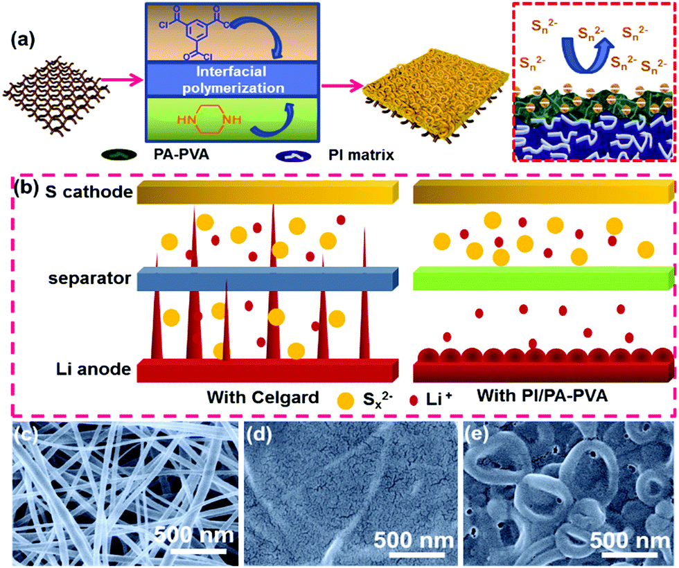 | ||
| Fig. 1 (a) Schematic diagrams of the preparation process of the PI/PA–PVA separator and the relevant repulsion mechanism for LPS. (b) Schematic diagrams of the growth of Li dendrites on anodes in Li–S batteries with Celgard and PI/PA–PVA separators. SEM images of the (c) PI, (d) PI/PA and (e) PI/PA–PVA separators. | ||
Results and discussion
The PI nanofiber membrane was fabricated as a separator by electrospinning with a synthesized polyamide acid solution, followed by imidization, which can be further used as the substrate for the preparation of the PI/PA and PI/PA–PVA separators due to the existence of both van der Waals (VDW) force and strong intermolecular hydrogen bonds.46,49,50 Zeta potentials of these PI nanofiber-based separators and the Celgard separator were measured to evaluate surface charge properties (Fig. S1, ESI†). As expected, the PI/PA–PVA separator is in a highly negatively-charged state as compared to the PI, PI/PA and Celgard separators. This is because the PI–PVA top layer can endow the PI/PA–PVA separator with a highly negative charge due to the interactions among PI, PA and PVA components induced by the existence of hydrogen bonds and the formed chemical bond through an esterification reaction between the carboxyl groups of PI and the hydroxy groups of PVA.51 Besides, the corresponding chemical structures of PI, PI/PA and PI/PA–PVA separators were extensively characterized via FTIR spectroscopy (Fig. S2, ESI†). In contrast with the PI separator, a new characteristic peak appears at 1630 cm−1 in the spectra of PI/PA and PI/PA–PVA separators, which is ascribed to the amide I band of aromatic PA.52 What is more, it is worth mentioning that, for PI/PA and PI/PA–PVA separators, the fragile broad peaks in the range of 3200–3500 cm−1 are assigned to O–H and N–H stretching vibrations, indicating the successful formation of PA via interfacial polymerization.53 Unlike the morphology of the Celgard separator (Fig. S3, ESI†), the PI separator consists of uniform nanofibers with a diameter of about 300 nm (Fig. 1c). After interfacial polymerization of the PI/PA separator, its PI nanofiber membrane surface was covered by a dense PA layer in a regular manner (Fig. 1d), which caused the corresponding decrease in both porosity and permeability. Remarkably, after adding a certain amount of PVA into the PI/PA separator, the PA–PVA layer with a dense Turing structure can be constructed over the PI substrate (Fig. 1e), which shows a thickness of about 15 μm for the Turing structure of the PA–PVA top layer and about 20 μm for the PI nanofiber membrane through the SEM image of the cross-section of the PI/PA–PVA separator and thereby enlarges the effective permeation area for electrolyte access (Fig. S4a, ESI†).Furthermore, the wettability, porosity and electrolyte uptake and retention of these separators were also quantitatively examined because these inherent properties take the prominent function in the comprehensive performance of Li–S batteries. The wettability of the separators for the electrolyte was typically evaluated via contact angle measurements. As shown in Fig. 2a and Table S1 (ESI†), it can be observed that the contact angle of the PI/PA–PVA separator is measured to be 0°, which is equal to that of the PI separator (0°) but significantly lower than that of the PI/PA separator (35.8°), indicating its favourable affinity toward the electrolyte. As for the Celgard separator, its contact angle raises to 49.2°, hence resulting in an unsatisfactory adsorption ability for the electrolyte.54,55 Then the membrane porosity of separators was analyzed using a liquid absorption method as it is mainly responsible for the electrolyte uptake performance in a battery system.26 Benefiting from the interconnected fibrous structure of nanofiber membranes, even though the porosity of the PI/PA–PVA separator was determined to be 75.1% smaller than those of the PI/PA (76.6%) and PI separators (92.1%) as shown in Table S1 (ESI†), it is still much higher than that of the Celgard separator (41.3%), thus approving the electrolyte uptake. Accordingly, the electrolyte uptake values of PI, PI/PA and PI/PA–PVA separators were calculated to be 2011%, 1321% and 1640%, respectively, while it declines to 156% for the Celgard separator under steady state conditions after 15 minutes, as demonstrated in Fig. 2b and Table S1 (ESI†). In addition, the electrolyte retention capability is another crucial parameter to determine the durability of the liquid electrolyte entrapped in the separators. As displayed in Fig. 2c and Table S2 (ESI†), when stored at 50 °C, the electrolyte retention values of PI and PI/PA–PVA separators were stabilized at 70.2% and 52.6% after 80 min, whereas it decreases to 41.1% for the PI/PA separator after 80 min, and merely 11.5% for the Celgard separator after 190 min. Through the above comparison, it is known that the PI/PA–PVA separator affords the best electrolyte retention capability among these separators. Therefore, the introduction of the electronegative PA–PVA top layer with a dense Turing structure can not only improve the polarity of the PI/PA–PVA separator to provide better affinity toward the electrolyte but also availably block the electrolyte inside this separator.
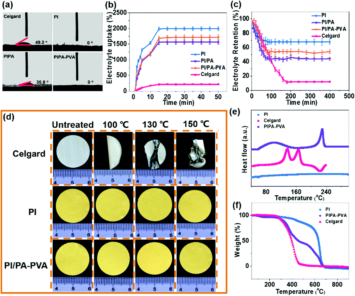 | ||
| Fig. 2 (a) Electrolyte contact angles, (b) electrolyte uptake and (c) electrolyte retention of the PI, PI/PA, PI/PA–PVA and Celgard separators. (d) Digital photos showing the thermal shrinkage of the PI, PI/PA–PVA and Celgard separators at different temperatures. (e) DSC and (f) TGA curves of the PI, PI/PA–PVA and Celgard separators. | ||
The thermal stability of the separator can be assessed by gauging its dimensional change under different gradient temperature conditions, which is related to the Li–S battery safety. As shown in Fig. 2d, the commercial Celgard separator shrinks and curls quickly and is eventually destroyed as the heating temperature increases from 100 °C to 150 °C.56,57 On the contrary, no visible dimensional variation occurs for PI and PI/PA–PVA separators in this temperature range, which is due to the excellent thermo-tolerance of the PI substrate. Furthermore, DSC measurements illustrate that there are two endothermic peaks at 136.5 °C and 166.2 °C in the curve of the Celgard separator while no apparent peaks can be recognized for the PI separator (Fig. 2e). Regarding the PI/PA–PVA separator, there are two endothermic peaks appearing at around 100 °C and 230 °C in the DSC curve, which are indexed to the melting point of PA and PVA ingredients, respectively. Besides, the TGA indicates that the weight loss of the Celgard and PI separators starts from about 295 °C and 414 °C, respectively (corresponding to 10wt% loss, Fig. 2f), whereas, for the PI/PA–PVA separator, the weight loss can be divided into three stages at about 308 °C, 350 °C and 532 °C, which are ascribed to the thermal degradation of PVA, PA and PI components, respectively. These results elucidate that the PA–PVA top layer will melt itself and block the separator pores at high Li–S battery working temperatures, while the PI substrate can maintain the complete dimension of the separator due to its excellent thermal tolerance. Consequently, its unique self-closing property can protect the batteries from short circuit at high working temperatures, which is significantly beneficial for the Li–S battery safety (Fig. S4b, ESI†).
The retarding ability of the separators for LPS can be considered as an indispensable parameter for the Li–S battery performance, which can be visually judged by diffusion tests that are conducted with a double-L device when the Li2S6 solution and pristine electrolyte are separated by two different membranes. As shown in Fig. S5a (ESI†), the palpable transmembrane penetration of LPS can be clearly detected for this device with the Celgard separator, while the electrolyte still remains clear even after 12 h when the PI/PA–PVA separator is utilized in this system, demonstrating its effectively prohibitive diffusion for LPS in the electrolyte solution (Fig. S5b, ESI†). This is mainly attributed to the highly negatively-charged environment constructed by the introduction of the PA–PVA top layer onto the PI substrate (Fig. S1, ESI†), which can restrain the electronegative LPS via electrostatic repulsion. At the same time, the Li–S battery performance is also crucially dependent on the Li+ transport property throughout the separators. Hence, the Li+ transference number and ionic conductivity were determined via AC impedance and chronoamperometry and EIS analysis as shown in Fig. 3a–d and Fig. S6 (ESI†), and the relevant results are shown in Fig. 3e. It can be seen that the Li+ transference numbers of PI, PI/PA, PI/PA–PVA and Celgard separators were calculated to be 0.54, 0.50, 0.70 and 0.45, respectively. Accordingly, the PI/PA–PVA separator shows the highest Li+ transference number among these separators. Moreover, the PI/PA–PVA separator reveals an excellent ionic conductivity of 2.28 when compared with PI (1.0), PI/PA (0.81), and Celgard separators (0.61). From the above results, although the membrane porosity of the PI/PA–PVA separator decreases after interfacial polymerization, the corresponding Li+ transference number and ionic conductivity still increase. This certainly benefits from its better electrolyte affinity and the highly electronegative PA–PVA top layer, which would facilitate the positively charged Li+ transport via electrostatic attraction. In contrast, the Celgard separator shows unsatisfied Li+ transfer ability and ionic conductivity due to its poor electrolyte affinity, low porosity and inferior electrolyte uptake and retention. Besides, from the I–V curves of the Li–S batteries assembled with PI, PI/PA–PVA and Celgard separators as shown in Fig. 3f, it can be concluded that the use of the PI/PA–PVA separator in Li–S batteries occupies a much broader electrochemical stability window than the other two separators, demonstrating that its appealing application can be extended to the field of high voltage Li–S batteries. Moreover, the open circuit voltage (OCV) was applied here to illustrate the self-discharge behaviour of Li–S batteries with PI, PI/PA, PI/PA–PVA and Celgard separators. As shown in Fig. S7 (ESI†), the OCVs of Li–S batteries with PI, PI/PA and Celgard separators decay seriously to 2.45 V, 2.55 V and 2.50 V in just a few hours, respectively. However, the OCV still maintains a larger value of 2.64 V after 13 h for the PI/PA–PVA separator. These results confirm that the self-discharge phenomenon can be effectively depressed in Li–S batteries when utilizing the PI/PA–PVA separator.
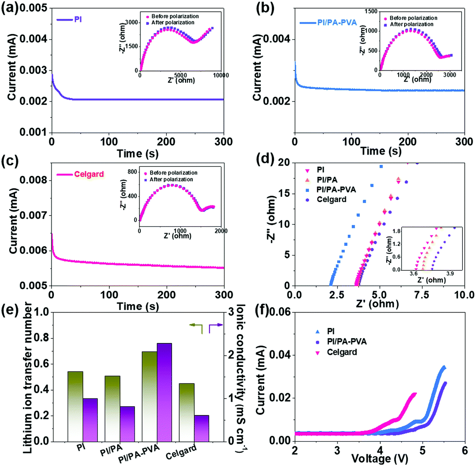 | ||
| Fig. 3 Chronoamperometry profiles of (a) PI/PA–PVA, (b) PI and (c) Celgard separators. The insets show the impedance values under the initial and steady-state current conditions. (d) Impedance plots estimating the Li+ conductivity of PI, PI/PA, PI/PA–PVA and Celgard separators. (e) Li+ transference number and ionic conductivity of PI, PI/PA, PI/PA–PVA and Celgard separators. (f) I–V curves of the Li–S batteries assembled with PI, PI/PA–PVA and Celgard separators. | ||
The CV curves of the Li–S batteries assembled with PI/PA–PVA, PI and Celgard separators at a scan rate of 0.1 mV s−1 are displayed in Fig. 4a and Fig. S8a, b (ESI†). Obviously, there are two cathodic peaks appearing at around 2.35 V and 2.10 V corresponding to the reduction of sulfur to long-chain LPS (SX2−, 4 < X ≤ 8) and further reduction to Li2S2 or Li2S, respectively. Meanwhile, the anodic peaks at around 2.33 V and 2.42 V are relative to the oxidation of LPS to sulfur.58 Compared with Li–S batteries with PI and Celgard separators, the CV curves of the initial three cycles are nearly overlapped for the Li–S battery with the PI/PA–PVA separator, indicating its high reversibility and improved LPS redox kinetics. In addition, to investigate the Li+ diffusion coefficients (DLi+) for these separators, the CV curves obtained at different scan rates were recorded (Fig. 4b and Fig. S8c, d, ESI†).59 The values can be calculated from the slope of the linear fitting curve between the square root of scan rate (V0.5) and the peak current (Ip) using Randles–Sevcik equation (Fig. 4c and Fig. S8e, f, ESI†), and the results are summarized in Fig. S9 (ESI†). The Li–S battery fabricated with the PI/PA–PVA separator possesses the highest Li+ diffusion coefficients (DLi+ (O2) = 5.13 × 10⁻⁶, DLi+ (R1) = 3.97 × 10⁻⁶, DLi+ (R2) = 2.09 × 10⁻⁶) among these separators even though its PI nanofiber substrate is covered by a dense top layer. These results demonstrate that the successful architecture of the negatively charged PA–PVA top layer imparts the PI/PA–PVA composite separators with strong inhibitive ability for LPS and a high Li+ diffusion coefficient when integrated with a Li–S battery.
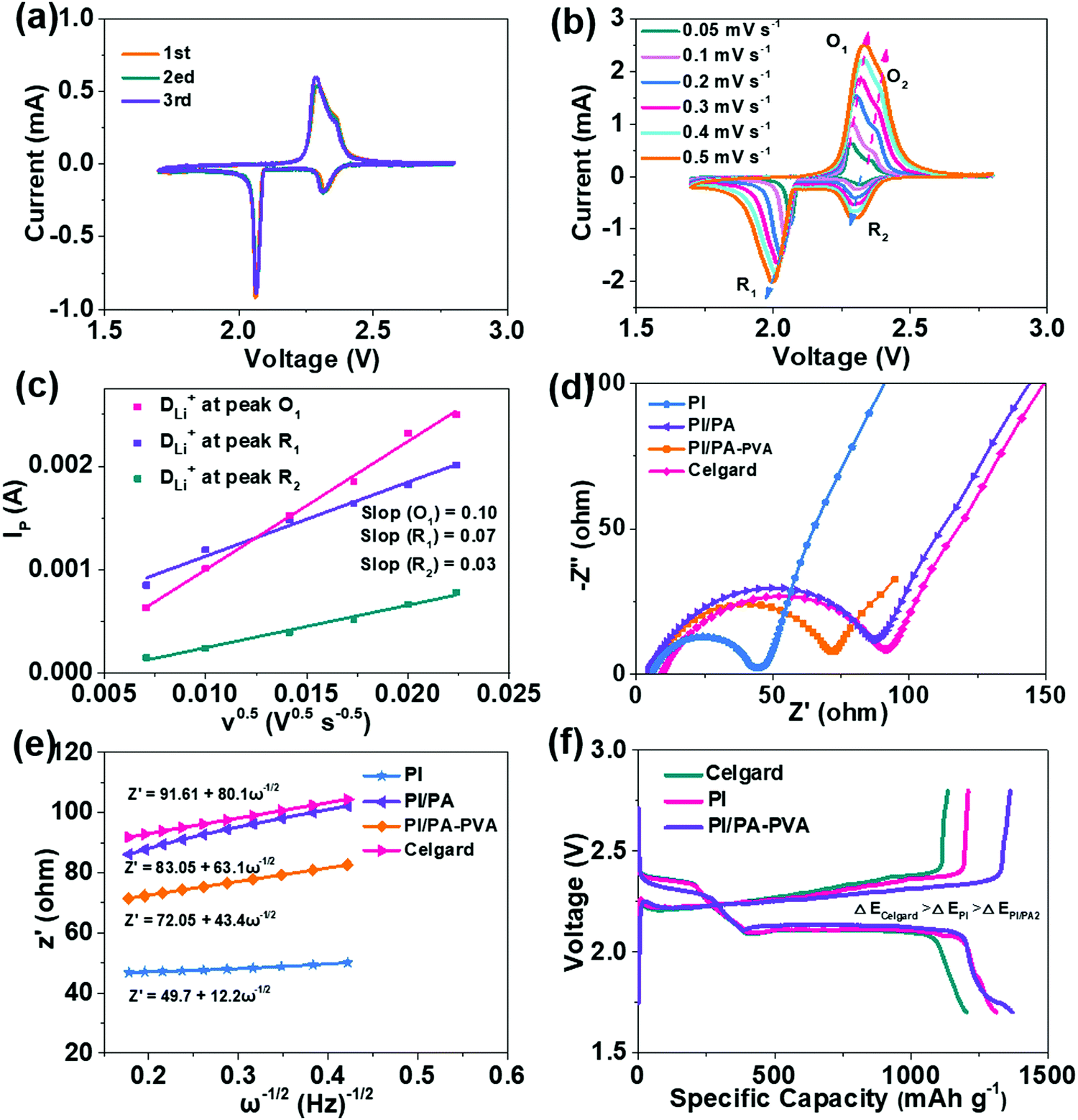 | ||
| Fig. 4 (a) CV curves of the battery with the PI/PA–PVA separator obtained at a scanning rate of 0.1 mV s−1. (b) CV curves of the battery with the PI/PA–PVA separator obtained at different scanning rates and (c) corresponding linear fits of peak currents. (d) Electrochemical impedance spectra of batteries with PI, PI/PA, PI/PA–PVA and Celgard separators after three test cycles and (e) relationships between Z′ and ω−0.5 in the low-frequency region. (f) Discharge and charge curves at 0.1C of batteries with Celgard, PI and PI/PA–PVA separators. | ||
The electrochemical kinetics of Li–S batteries assembled with PI, PI/PA, PI/PA–PVA and Celgard separators were determined using the EIS analysis as shown in Fig. 4d. The charge-transfer resistance (Rct) of Li–S batteries with PI nanofiber-based separators is rather smaller than that of the Celgard separator (91 Ω). Among them, the Rct of the Li–S battery with the PI/PA separator is much increased as compared with the value of the battery with the PI separator since the distributed pores over the PI nanofiber membrane are fully covered by the PA top layer. However, by comparison, the Rct can be further decreased for the Li–S battery with the PI/PA–PVA separator due to its formation of the PA–PVA top layer with a Turing structure with approvable features such as a high specific surface area, abundant permeation sites and desirable electrolyte affinity, which are beneficial for its faster Li+ diffusion rate. The relationships between the linear fittings of Z′ and the square root in the low-frequency region (ω−0.5) are shown in Fig. 4e, the slope of which represents the Warburg factor to determine the Li+ diffusion transportation.60 It can be observed that the slopes of Li–S batteries with PI, PI/PA and PI/PA–PVA separators are 12.2, 63.1 and 43.4, respectively, which are much less than that for the Celgard separator (80.1), further confirming that the PI nanofiber-based separators show better Li+ transportation in the Li–S battery. The galvanostatic discharge–charge profiles of Li–S batteries assembled with PI, PI/PA–PVA and Celgard separators at 0.1C are displayed in Fig. 4f. The two plateaus on discharge curves represent the redox of sulfur to long-chain LPS and further to short-chain LPS, while the plateau on charge curves refer to the transition of short-chain LPS to sulfur. Apparently, the Li–S battery with the PI/PA–PVA separator exhibits a much lower overpotential than those with the PI and Celgard separators, indicating its superior electrochemical reversibility.
In order to further unveil electrochemical properties, the discharge–charge curves at different C-rates are analyzed for Li–S batteries with these separators (Fig. 5a–c and Fig. S10, ESI†). It can be seen that all of the discharge curves display a typical two-plateau characteristic under lower current densities. In this regard, the PI/PA–PVA separator affords the highest specific capacity among them, which decreases with increasing the current rate from 0.1C to 5C. In particular, the initial specific capacity of the Li–S battery with the PI/PA–PVA separator can reach values as high as 1499 mA g−1 at 0.1C. Besides, when the current-rate is switched from 5C back to 0.1C, the Li–S battery assembled with the PI/PA–PVA separator has exhibited better recovery ability of discharge capacity than those with PI, PI/PA and Celgard separators, thus reflecting its excellent stability (Fig. 5d). Furthermore, the cycle stabilities of Li–S batteries assembled with these separators were further evaluated at 0.2C. As shown in Fig. 5e, their rapid capacity loss during the initial cycles are mainly triggered by the formation of SEI and the dissolution and shuttling of lithium polysulfides.61–63 More specifically, for the PI separator, the high initial capacity decays very fast in the subsequent cycles, but its decay rate is much lower than that of the Celgard separator. After interfacial polymerization of the PI/PA separator, the cycle stability of the Li–S battery is promoted because of the inhibited shuttling of LPS and the better Li+ transportation by the negatively charged PA top layers.64 Moreover, the electronegativity of the PA layer is further enhanced after the addition of PVA for the formation of the PI/PA–PVA separator, which in turn guarantees a high utilization rate of the S active component and strengthens the cycle stability of the Li–S battery (Fig. 5f). It can be inferred that the loss phenomenon of the S active component on the cathode of the Li–S battery with the PI/PA–PVA separator can be effectively restrained, which can also be visually identified via energy dispersive X-ray spectroscopy (EDS) (Fig. S11, ESI†). As a consequence, the Li–S battery with the PI/PA–PVA separator presents a stable discharge capacity of 852 mA h g−1 with an ultralow fading rate of 0.1% per cycle after 500 cycles (Fig. 5g and Table S2, ESI†).
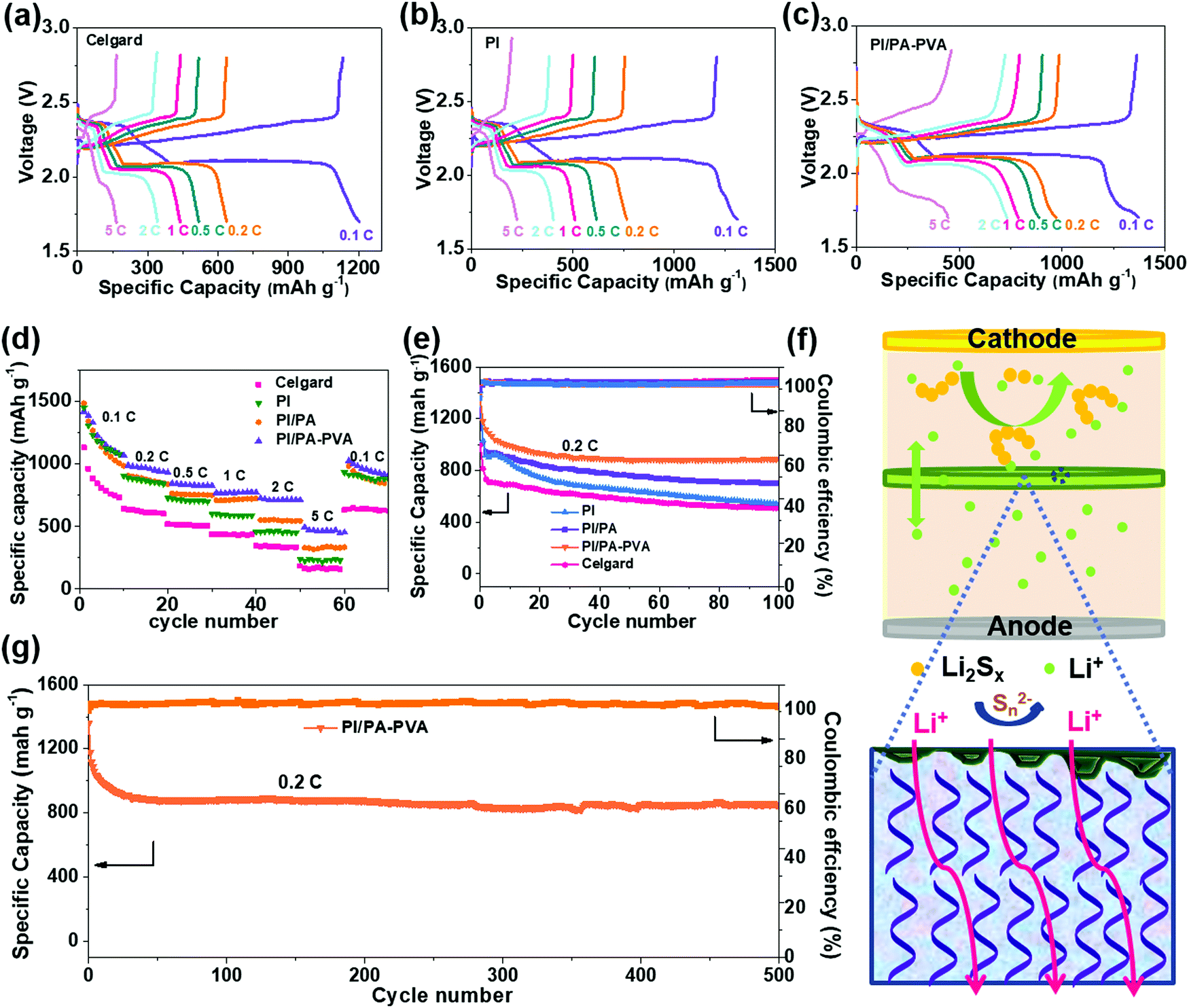 | ||
| Fig. 5 (a–c) First cycle discharge and charge curves at different rates for Li–S batteries with Celgard, PI and PI/PA–PVA separators. (d) Rate performance at 0.1C, 0.2C, 0.5C, 1C, 2C, and 5C and (e) galvanostatic cycling performance at 0.2C of Li–S batteries with PI, PI/PA, PI/PA–PVA and Celgard separators. (f) Schematic illustration showing the rejection mechanism of the PI/PA–PVA separator for LPS during the discharge process. (g) Long cycling performance of batteries with PI/PA–PVA separators at 0.2C. | ||
Furthermore, Li/Li symmetric batteries were integrated with PI/PA–PVA and Celgard separators in order to investigate the interfacial stability of the Li anode in the electrolyte. It can be observed from Fig. 6a that both batteries display relatively high overpotentials in the first few cycles due to the electrode activation and the formation of the SEI layer.65 For the Li–S battery with the PI/PA–PVA separator, the striping and plating of Li gives a low and stable overpotential below 100 mV for over 600 h, indicating a uniform Li deposition and a stable SEI layer formed on the anode. In contrast, the Li–S battery with the Celgard separator exhibits an ultrahigh and unstable overpotential which is more than 200 mV and it increases gradually with cycle time. This unwanted phenomenon mainly results from the formation of Li dendrites on the anode in Li–S batteries, thus causing the continuous destruction and rebuilding of the SEI layer. Besides, the surface morphologies of the Li anode before and after cycling were analyzed via SEM characterization. The pristine Li tablet has a flat and smooth surface morphology (Fig. S12, ESI†). After cycling of the Li–S battery assembled with the Celgard separator, the Li anode was corroded seriously accompanied with visible Li dendrites (Fig. 6b). In contrast, the Li anode remains relatively flat when using the PI/PA–PVA separator (Fig. 6c). In addition, the EDS mapping analysis visually illustrates that there is a large amount of sulfur remaining on the Li anode when using the Celgard separator, which is ascribed to the diffusion of LPS (Fig. 6d). But, for the battery using the PI/PA–PVA separator, there is little sulfur left on the Li anode after cycling (Fig. 6e). The above evidence directly demonstrates that the PI/PA–PVA separator can prevent the Li anode from the shuttle effect of LPS and dendrite growth simultaneously. This is mainly because the negatively charged PA–PVA layer with a dense Turing structure can not only suppress the LPS shuttling through the separator, but also promote the rapid and uniform transmembrane diffusion of Li+ which results in decelerated Li+ depletion and improved homogeneous Li deposition.
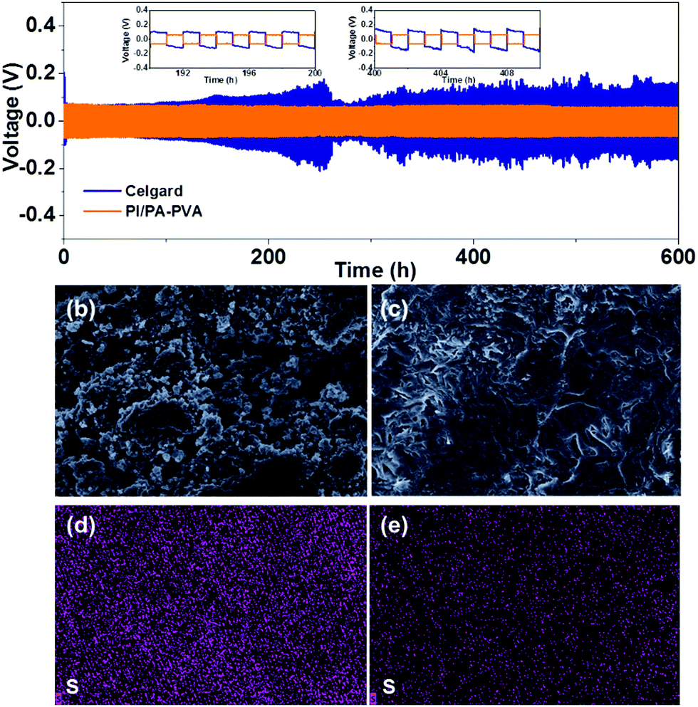 | ||
| Fig. 6 (a) Voltage–time profile of Li–Li symmetric cells using Celgard and PI/PA–PVA separators at 1 mA cm−2 with a capacity of 1 mA h cm−2. (b–e) SEM images and the corresponding elemental mappings of lithium anodes after rate performance tests with Celgard and PI/PA–PVA separators. | ||
Experimental
Chemical and materials
Trimesoyl chloride (TMC, >98.0%), piperazine anhydrous (PIP, >99.0%), polyvinyl alcohol (PVA, Mw 85![[thin space (1/6-em)]](https://www.rsc.org/images/entities/char_2009.gif) 000–124000, 87–89% hydrolyzed), pyromellitic dianhydride (PMDA) and 4,4′-oxydianiline (ODA) were purchased from Sigma-Aldrich. N-Hexane and N,N-methyl-2-pyrrolidone (NMP) were supplied by Shanghai Chemistry Company, which were further dehydrated with CaH2 and purified via further distillation.
000–124000, 87–89% hydrolyzed), pyromellitic dianhydride (PMDA) and 4,4′-oxydianiline (ODA) were purchased from Sigma-Aldrich. N-Hexane and N,N-methyl-2-pyrrolidone (NMP) were supplied by Shanghai Chemistry Company, which were further dehydrated with CaH2 and purified via further distillation.
Preparation of the composite separators
Firstly, ODA (0.64 g, 1.50 mmol) was dissolved in NMP (30 mL), and then PMDA (1.50 mmol) was added at 0 °C with mechanical stirring. The mixture was maintained at 0 °C for 3 h to completely polymerize and then the polyamide acid (PAA) spinning solution was obtained (Fig. S13, ESI†). Then the electrospinning process was conducted at room temperature at a pushing speed of 0.06 mm min−1. The distance between the tip of the spinneret and the collector was 20 cm with a voltage of 18–25 kV. PI nanofiber membranes with a thickness of about 30 μm were obtained via the imidization of PAA nanofiber membranes at 300 °C for 3 h. After that, interfacial polymerization was conducted at room temperature and the specific conditions of the interfacial polymerization processes are listed in Table S3 (ESI†). Firstly, the porous PI nanofiber membrane was immersed in an aqueous solution of PIP with 0.6 wt% triethylamine as the acid acceptor (and PVA for partial samples) for 5 min. The soaked PI substrate was dried at room temperature until there was no excess liquid on the surface. Subsequently, n-hexane containing TMC was dropped on the PI substrate and maintained for 1 min, followed by post-treatment at 80 °C for 10 min to form the complete PA–PVA layer. Finally, the as-prepared composite membrane was washed with de-ionized (DI) water to remove the residual monomer and finally vacuum-dried at 50 °C for 12 h. The samples containing PVA are named PI/PA–PVA, while those without PVA are denoted as PI/PA.Materials characterization
Fourier transform infrared spectroscopy (FTIR, NicoletIn10MX/Nicolet6700, NicoletIn10MX/Nicolet6700, Thermo Fisher, USA) was utilized to characterize the chemical structures of the membranes. Thermogravimetric analysis (TGA, NETZSCH TG 209 F1 Libra) was performed under an air atmosphere and differential scanning calorimetry (DSC, Q2000, TA, USA) was conducted from 40 to 240 °C with a heating rate of 20 °C min−1 to analyze the thermal properties of different separators. The morphological structures of the membranes were detected using a field emission scanning electron microscope (FESEM, S4800, Hitachi, Japan). Contact angles (Shanghai Zhongchen Digital Technology Apparatus Co., Ltd) were measured to characterize the affinity of separators to the electrolyte.The porosity of the separators was characterized through a liquid absorption method and calculated according to the following eqn (1):66
| Porosity = (Ww − Wd)/(ρ × V) | (1) |
The electrolyte uptake and retention of the separators is calculated through the following eqn (2):
| Electrolyte uptake = (W1 − W0)/(W0 × 100%) | (2) |
| Electrolyte retention = [(Wx − W0)/(W1 − W0)] × 100% | (3) |
Evaluation of the electrochemical performance
The sulfur cathode was prepared by casting a mixture of 70 wt% sulfur, 20 wt% carbon powders, and 10 wt% PVDF in NMP on an Al current collector with a sulfur loading of 1.5–2.2 mg cm−2. CR2032 coin type cells were assembled using sulfur cathodes and lithium metal anodes in an argon-filled glove box. The diameters of the separator and Li anode were 18 mm and 16 mm, respectively. For all batteries, the electrolyte used was 30 μL of 1.0 M LiTFSI in DOL/DME (1:1 by volume) with 2 wt% LiNO3. The galvanostatic discharge–charge performance was tested on a battery-testing system (LAND CT2001A, Wuhan, China). Cyclic voltammetry (CV) and electrochemical impedance spectroscopy (EIS) were conducted on an electrochemical workstation (CHI660E, Wuhan, China) with the voltage ranging from 1.7 to 2.8 V.
The ionic conductivity was detected via EIS with the frequency ranging from 0.1 Hz to 100 kHz and calculated according to the following eqn (4):
| ó = L/(Rb × A) | (4) |
The lithium ion transference number (tLi+) of the separators was also evaluated via EIS combined with chronoamperometry, which can be calculated according to the following eqn (5):67
| tLi+ = Is(ΔV − I0R0)/I0(ΔV − IsRs) | (5) |
Linear sweep voltammetry (LSV) was performed on another electrochemical workstation (CHI660D, Wuhan, China) with a scan rate of 1 mV s−1. The cells used for this measurement were fabricated by placing the separator between a stainless steel and a lithium foil.
Conclusions
In summary, we designed and fabricated a multifunctional PI/PA–PVA separator with a self-closing top layer with a Turing structure via electrospinning and interfacial polymerization. The synergy of the nanofibrous PI membrane and the PA–PVA top layer endows it with better wettability, high electrolyte uptake and good retention. Meanwhile, the highly negatively charged PA–PVA layer with a dense Turing structure can suppress the shuttle effect of LPS, promote the transfer of the positively charged Li+ and simultaneously regulate the uniform deposition of Li on the anode to restrain the growth of Li dendrites. Besides, the self-closing property of the PA–PVA layer and the outstanding thermal stability of the PI substrate bestow excellent safety performance to the Li–S battery at high temperatures. As a result, the Li–S battery assembled with the PI/PA–PVA separator exhibited an initial specific capacity of 1499 mA g−1 at 0.1C and outstanding cycle stability with a negligible fading rate of 0.1% per cycle at 0.2C over 500 cycles. We believe that the fabrication strategy proposed here can provide a new method for developing high-performance separators for commercially viable Li–S batteries.Conflicts of interest
The authors declare no conflict of interest.Acknowledgements
This project was financially supported by the Startup Research Fund of Dongguan University of Technology (KCYKYQD2017015), the Postdoctoral Startup Research Fund of Dongguan University of Technology (No. 196100040019), and the Leading Talents of Innovation and Entrepreneurship of the Dongguan City D2017(16).Notes and references
- Y. Z. Wang, X. Y. Shan, L. P. Ma, J. W. Wang, D. W. Wang, Z. Q. Peng, H. M. Cheng and F. Li, A Desolvated Solid-Solid-Solid Interface for a High-Capacitance Electric Double Layer, Adv. Energy Mater., 2019, 9, 1803715 CrossRef.
- M. P. Down, E. Martínez-Periñán, C. W. Foster, E. Lorenzo, G. C. Smith and C. E. Banks, Next-Generation Additive Manufacturing of Complete Standalone Sodium-Ion Energy Storage Architectures, Adv. Energy Mater., 2019, 9, 1803019 CrossRef.
- Y. L. Ji, M. A. Goulet, D. A. Pollack, D. G. Kwabi, S. J. Jin, D. De Porcellinis, E. F. Kerr, R. G. Gordon and M. J. Aziz, A Phosphonate-Functionalized Quinone Redox Flow Battery at Near-Neutral pH with Record Capacity Retention Rate, Adv. Energy Mater., 2019, 9, 1900039 CrossRef.
- L. T. Ma, S. M. Chen, D. H. Wang, Q. Yang, F. N. Mo, G. J. Liang, N. Li, H. Y. Shang, J. A. Zapien and C. Y. Zhi, Super-Stretchable Zinc Air Batteries Based on an Alkaline-Tolerant Dual-Network Hydrogel Electrolyte, Adv. Energy Mater., 2019, 9, 1803046 CrossRef.
- A. Sugahara, Y. Ando, S. Kajiyama, K. Yazawa, K. Gotoh, M. Otani and M. A. Yamada, Negative dielectric constant of water confined innanosheets, Nat. Commun., 2019, 10, 1038 CrossRef.
- H. J. Peng, W. T. Xu, L. Zhu, D. W. Wang, J. Q. Huang, X. B. Cheng, Z. Yuan, F. Wei and Q. Zhang, 3D Carbonaceous Current Collectors: The Origin of Enhanced Cycling Stability for High-Sulfur-Loading Lithium-Sulfur Batteries, Adv. Funct. Mater., 2016, 26, 6351 CrossRef CAS.
- Z. H. Li, Q. He, X. Xu, Y. Zhao, X. W. Liu, C. Zhou, D. Ai, L. X. Xia and L. Q. Mai, A 3D Nitrogen-Doped Graphene/TiN Nanowires Composite as a Strong Polysulfide Anchor for Lithium-Sulfur Batteries with Enhanced Rate Performance and High Areal Capacity, Adv. Mater., 2018, 30, 1804089 CrossRef.
- C. Luo, Y. J. Zhu, O. Borodin, T. Gao, X. L. Fan, Y. H. Xu, K. Xu and C. S. Wang, Activation of Oxygen-Stabilized Sulfur for Li and Na Batteries, Adv. Funct. Mater., 2016, 26, 745 CrossRef CAS.
- Q. Pang, X. Liang, C. Y. Kwok and L. F. Nazar, Advances in lithium-sulfur batteries based on multifunctional cathodes and electrolytes, Nat. Energy, 2016, 1, 16132 CrossRef CAS.
- H. Q. Wang, W. C. Zhang, J. Z. Xu and Z. P. Guo, Advances in Polar Materials for Lithium-Sulfur Batteries, Adv. Funct. Mater., 2018, 28, 1707520 CrossRef.
- K. Dokko, N. Tachikawa, K. Yamauchi, M. Tsuchiya, A. Yamazaki, E. Takashima, J.-W. Park, K. Ueno, S. Seki and N. Serizawa, Solvate Ionic Liquid Electrolyte for Li-S Batteries, J. Electrochem. Soc., 2013, 160, A1304 CrossRef CAS.
- Z. B. Cheng, H. Pan, H. Zhong, Z. B. Xiao, X. J. Li and R. H. Wang, Porous Organic Polymers for Polysulfide Trapping in Lithium-Sulfur Batteries, Adv. Funct. Mater., 2018, 28, 1707597 CrossRef.
- X. Shen, X. B. Cheng, P. Shi, J. Q. Huang, X. Q. Zhang, C. Yan, T. Li and Q. Zhang, Lithium-matrix composite anode protected by a solid electrolyte layer for stable lithium metal batteries, J. Energy Chem., 2019, 37, 29 CrossRef.
- Y. Y. Zhao, Y. S. Ye, F. Wu, Y. J. Li, L. Li and R. J. Chen, Anode Interface Engineering and Architecture Design for High-Performance Lithium-Sulfur Batteries, Adv. Mater., 2019, 31, 1806532 CrossRef.
- L. L. Kong, L. Wang, Z. C. Ni, S. Liu, G. R. Li and X. P. Gao, Lithium-Magnesium Alloy as a Stable Anode for Lithium-Sulfur Battery, Adv. Funct. Mater., 2019, 29, 1808756 CrossRef.
- F. Pei, A. Fu, W. B. Ye, J. Peng, X. L. Fang, M. S. Wang and N. F. Zheng, Robust Lithium Metal Anodes Realized by Lithiophilic 3D Porous Current Collectors for Constructing High-Energy Lithium-Sulfur Batteries, ACS Nano, 2019, 13, 8337 CrossRef CAS.
- M. D. Tikekar, S. Choudhury, Z. Tu and L. A. Archer, Design principles for electrolytes and interfaces for stable lithium-metal batteries, Nat. Energy, 2016, 1, 16114 CrossRef CAS.
- H. F. Yan, H. C. Wang, D. H. Wang, X. Li, Z. L. Gong and Y. Yang, In Situ Generated Li2S-C Nanocomposite for High-Capacity and Long-Life All-Solid-State Lithium Sulfur Batteries with Ultrahigh Areal Mass Loading, Nano Lett., 2019, 19, 3280 CrossRef CAS.
- S. Kim, H. Oguchi, N. Toyama, T. Sato, S. Takagi, T. Otomo, D. Arunkumar, N. Kuwata, J. Kawamura and S. I. Orimo, A complex hydride lithium superionic conductor for high-energy-density all-solid-state lithium metal batteries, Nat. Commun., 2019, 10, 1081 CrossRef.
- R. C. Xu, J. Yue, S. F. Liu, J. P. Tu, F. D. Han, P. Liu and C. S. Wang, Cathode-Supported All-Solid-State Lithium-Sulfur Batteries with High Cell-Level Energy Density, ACS Energy Lett., 2019, 4, 1073 CrossRef CAS.
- X. Q. Zhang, X. B. Cheng, X. Chen, C. Yan and Q. Zhang, Fluoroethylene Carbonate Additives to Render Uniform Li Deposits in Lithium Metal Batteries, Adv. Funct. Mater., 2017, 27, 1605989 CrossRef.
- Z. Peng, F. H. Ren, S. S. Yang, M. Q. Wang, J. Sun, D. Y. Wang, W. Xu and J. G. Zhang, A highly stable host for lithium metal anode enabled by Li9Al4-Li3N-AlN structure, Nano Energy, 2019, 59, 110 CrossRef CAS.
- M. F. Lagadec, R. Zahn and V. Wood, Characterization and performance evaluation of lithium-ion battery separators, Nat. Energy, 2019, 4, 16 CrossRef CAS.
- Y. K. Ahn, J. Park, D. Shin, S. Cho, S. Y. Park, H. Kim, Y. Piao, J. Yoo and Y. S. Kim, Enhanced electrochemical capabilities of lithium ion batteries by structurally ideal AAO separator, J. Mater. Chem. A, 2015, 3, 10715 RSC.
- Y. M. Liu, X. Y. Qin, S. Q. Zhang, G. M. Liang, F. Y. Kang, G. H. Chen and B. H. Li, Fe3O4-Decorated Porous Graphene Interlayer for High-Performance Lithium-Sulfur Batteries, ACS Appl. Mater. Interfaces, 2018, 10, 26264 CrossRef CAS.
- Y. Wang, S. Q. Wang, J. Q. Fang, L. X. Ding and H. H. Wang, A nano-silica modified polyimide nanofiber separator with enhanced thermal and wetting properties for high safety lithium-ion batteries, J. Membr. Sci., 2017, 537, 248 CrossRef CAS.
- L. Pan, H. B. Wang, C. L. Wu, C. B. Liao and L. Li, Tannic-Acid-Coated Polypropylene Membrane as a Separator for Lithium-Ion Batteries, ACS Appl. Mater. Interfaces, 2015, 7, 16003 CrossRef CAS.
- J. H. Ahn, H. J. Shin, S. Abbas, K. Y. Lee and H. Y. Ha, Plasma-functionalized carbon-layered separators for improved performance of lithium sulfur batteries, J. Mater. Chem. A, 2019, 7, 3772 RSC.
- H. T. Qu, J. W. Ju, B. B. Chen, N. Xue, H. P. Du, X. Q. Han, J. J. Zhang, G. J. Xu, Z. Yu, X. G. Wang and G. L. Cui, Inorganic separators enable significantly suppressed polysulfide shuttling in high-performance lithium-sulfur batteries, J. Mater. Chem. A, 2018, 6, 23720 RSC.
- M. Tian, F. Pei, M. S. Yao, Z. H. Fu, L. L. Lin, G. D. Wu, G. Xu, H. Kitagawa and X. L. Fang, Ultrathin MOF nanosheet assembled highly oriented microporous membrane as an interlayer for lithium-sulfur batteries, Energy Storage Mater., 2019, 21, 14–21 CrossRef.
- Y. B. He, Z. Chang, S. C. Wu, Y. Qiao, S. Y. Bai, K. Z. Jiang, P. He and H. S. Zhou, Simultaneously Inhibiting Lithium Dendrites Growth and Polysulfides Shuttle by a Flexible MOF-Based Membrane in Li-S Batteries, Adv. Energy Mater., 2018, 8, 1802130 CrossRef.
- H. H. Chen, Y. W. Xiao, C. Chen, J. Y. Yang, C. Gao, Y. S. Chen, J. S. Wu, Y. Shen, W. N. Zhang, S. Li, F. W. Huo and B. Zheng, Conductive MOF-Modified Separator for Mitigating the Shuttle Effect of Lithium-Sulfur Battery through a Filtration Method, ACS Appl. Mater. Interfaces, 2019, 11, 11459 CrossRef CAS.
- X. J. Hong, C. L. Song, Y. Yang, H. C. Tan, G. H. Li, Y. P. Cai and H. X. Wang, Cerium Based Metal-Organic Frameworks as an Efficient Separator Coating Catalyzing the Conversion of Polysulfides for High Performance Lithium-Sulfur Batteries, ACS Nano, 2019, 13, 1923 CAS.
- X. Liu, J. Q. Huang, Q. Zhang and L. Q. Mai, Nanostructured Metal Oxides and Sulfides for Lithium-Sulfur Batteries, Adv. Mater., 2017, 29, 1601759 CrossRef.
- T. Yim, S. H. Han, N. H. Park, M. S. Park, J. H. Lee, J. Shin, J. W. Choi, Y. Jung, Y. N. Jo, J. S. Yu and K. J. Kim, Effective Polysulfide Rejection by Dipole-Aligned BaTiO3 Coated Separator in Lithium-Sulfur Batteries, Adv. Funct. Mater., 2016, 26, 7817 CrossRef CAS.
- J. Y. Hwang, H. M. Kim, S. Shin and Y. K. Sun, Designing a High-Performance Lithium Sulfur Batteries Based on Layered Double Hydroxides Carbon Nanotubes Composite Cathode and a Dual-Functional Graphene-Polypropylene-Al2O3 Separator, Adv. Funct. Mater., 2018, 28, 1704294 CrossRef.
- X. H. Feng, Q. Wang, R. R. Li and H. Li, CoFe2O4 coated carbon fiber paper fabricated via a spray pyrolysis method for trapping lithium polysulfide in Li-S batteries, Appl. Surf. Sci., 2019, 478, 341 CrossRef CAS.
- H. Y. Pan, Z. Tan, H. H. Zhou, L. L. Jiang, Z. Y. Huang, Q. X. Feng, Q. Zhou, S. Ma and Y. F. Kuang, Fe3C-N-Doped Carbon Modified Separator for High Performance Lithium-Sulfur Batteries, J. Energy Chem., 2019, 39, 101 CrossRef.
- X. B. Zhu, Y. Ouyang, J. W. Chen, X. G. Zhu, X. Luo, F. L. Lai, H. Zhang, Y. E. Miao and T. X. Liu, In situ extracted poly(acrylic acid) contributing to electrospun nanofiber separators with precisely tuned pore structures for ultra-stable lithium-sulfur batteries, J. Mater. Chem. A, 2019, 7, 3253 RSC.
- X. Luo, X. B. Lu, G. Y. Zhou, X. Y. Zhao, Y. Ouyang, X. B. Zhu, Y. E. Miao and T. X. Liu, Ion-Selective Polyamide Acid Nanofiber Separators for High-Rate and Stable Lithium-Sulfur Batteries, ACS Appl. Mater. Interfaces, 2018, 10, 42198 CrossRef CAS.
- W. Xu, J. L. Wang, F. Ding, X. L. Chen, E. Nasybulin, Y. H. Zhang and J. G. Zhang, Lithium metal anodes for rechargeable batteries, Energy Environ. Sci., 2014, 7, 513 RSC.
- N. Liu, Z. D. Lu, J. Zhao, M. T. McDowell, H. W. Lee, W. T. Zhao and Y. Cui, A pomegranate-inspired nanoscale design for large-volume-change lithium battery anodes, Nat. Nanotechnol., 2014, 9, 187 CrossRef CAS.
- L. Kong, Q. Jin, X. T. Zhang, B. Q. Li, J. X. Chen, W. C. Zhu, J. Q. Huang and Q. Zhang, Towards Full Demonstration of High Areal Loading Sulfur Cathode in Lithium–Sulfur Batteries, J. Energy Chem., 2019, 39, 17 CrossRef.
- J. Q. Huang, Q. Zhang, H. J. Peng, X. Y. Liu, W. Z. Qian and F. Wei, Ionic Shield for Polysulfides Towards Highly - Stable Lithium-Sulfur Batteries, Energy Environ. Sci., 2014, 7, 347 RSC.
- J. E. Cadotte, R. S. King, R. J. Majerle and R. J. Petersen, Interfacial Synthesis In The Preparation Of Reverse-Osmosis Membranes, J. Macromol. Sci., Chem., 1981, 15, 727 CrossRef.
- Z. Tan, S. F. Chen, X. S. Peng, L. Zhang and C. J. Gao, Polyamide membranes with nanoscale Turing structures for water purification, Science, 2018, 360, 518 CrossRef CAS.
- Y. Xu, T. Yuan, Z. H. Bian, H. Sun, Y. P. Pang, C. X. Peng, J. H. Yang and S. Y. Zheng, Electrospun flexible Si/C@CNF nonwoven anode for high capacity and durable lithium-ion battery, Compos. Commun., 2019, 11, 1 CrossRef.
- W. Ouyang, S. W. Liu, K. Q. Yao, L. Y. Zhao, L. H. Cao, S. H. Jiang and H. Q. Hou, Ultrafine hollow TiO2 nanofibers from core-shell composite fibers and their photocatalytic properties, Compos. Commun., 2018, 9, 76–80 CrossRef.
- X. Luo, X. B. Lu, X. D. Chen, Y. Chen, C. Y. Yu, D. W. Su, G. X. Wang and L. F. Cui, A functional hyperbranched binder enabling ultra-stable sulfur cathode for high-performance lithium-sulfur battery, J. Energy Chem., 2020, 50, 63 CrossRef.
- B. J. Liu, W. Hu, G. P. Robertson and M. D. Guiver, Poly(aryl ether ketone)s with carboxylic acid groups: synthesis, sulfonation and crosslinking, J. Mater. Chem. A, 2008, 18, 4675 RSC.
- D. Hanaor, M. Michelazzi, C. Leonelli and C. C. Sorrell, The effects of carboxylic acids on the aqueous dispersion and electrophoretic deposition of ZrO2, J. Eur. Ceram. Soc., 2012, 32, 235 CrossRef CAS.
- A. Barth, Infrared spectroscopy of proteins, Biochim. Biophys. Acta, Biomembr., 2007, 1767, 1073 CrossRef CAS.
- M. N. Rantho, M. J. Madito, F. O. Ochai-Ejeh and N. Manyala, Asymmetric supercapacitor based on vanadium disulfide nanosheets as a cathode and carbonized iron cations adsorbed onto polyaniline as an anode, Electrochim. Acta, 2018, 260, 11 CrossRef CAS.
- X. F. Gui, L. L. Liu, S. X. Gao, L. F. Sun, K. Xu and M. C. Chen, A novel silsesquioxanes modified electrospun composite fibrous separator by in-situ crosslinking method for lithium-ion batteries, Mater. Lett., 2019, 242, 66 CrossRef CAS.
- G. Q. Dong, B. X. Liu, G. H. Sun, G. F. Tian, S. L. Qi and D. Z. Wu, TiO2 nanoshell@polyimide nanofiber membrane prepared via a surface-alkaline-etching and in-situ complexation-hydrolysis strategy for advanced and safe LIB separator, J. Membr. Sci., 2019, 577, 249 CrossRef CAS.
- M. B. Ibrahim and R. M. Kovach, A Klaina Cycle Application For Power-Generation, Energy, 1993, 18, 961 CrossRef CAS.
- G. C. Zguris, Advances in recombinant battery separator mat (RBSM) separators for lead-acid batteries – a review, J. Power Sources, 2002, 107, 187 CrossRef CAS.
- Y. H. Xu, Y. J. Zhu, F. D. Han, C. Luo and C. S. Wang, 3D Si/C Fiber Paper Electrodes Fabricated Using a Combined Electrospray/Electrospinning Technique for Li-Ion Batteries, Adv. Energy Mater., 2015, 5, 1400753 CrossRef.
- Y. B. Wang, C. J. Chen, H. Xie, T. T. Gao, Y. G. Yao, G. Pastel, X. G. Han, Y. J. Li, J. P. Zhao, K. K. Fu and L. B. Hu, 3D-Printed All-Fiber Li-Ion Battery toward Wearable Energy Storage, Adv. Funct. Mater., 2017, 27, 1703140 CrossRef.
- G. Y. Zhou, Y. E. Miao, Z. X. Wei, L. L. Mo, F. L. Lai, Y. Wu, J. M. Ma and T. X. Liu, Bioinspired Micro/Nanofluidic Ion Transport Channels for Organic Cathodes in High-Rate and Ultrastable Lithium/Sodium-Ion Batteries, Adv. Funct. Mater., 2018, 28, 1804629 CrossRef.
- R. M. Kasse, N. R. Geise, J. S. Ko, J. N. Weker, H. G. Steinruck and M. F. Toney, Understanding additive controlled lithium morphology in lithium metal batteries, J. Mater. Chem. A, 2020, 8, 16960 RSC.
- K. K. Hu, X. Z. Guan, R. J. Lv, G. J. Li, Z. L. Hu, L. B. Ren, A. X. Wang, X. J. Liu and J. Y. Luo, Stabilizing zinc metal anodes by artificial solid electrolyte interphase through a surface ion-exchanging strategy, Chem. Eng. J., 2020, 396, 125363 CrossRef CAS.
- S. Y. Lang, Z. Z. Shen, X. C. Hu, Y. Shi, Y. G. Guo, F. F. Jia, F. Y. Wang, R. Wang and L. J. Wan, Tunable structure and dynamics of solid electrolyte interphase at lithium metal anode, Nano Energy, 2020, 75, 104967 CrossRef CAS.
- E. P. Chan, J. J. Walish, E. L. Thomas and C. M. Stafford, Block Copolymer Photonic Gel for Mechanochromic Sensing, Adv. Mater., 2011, 23, 4702 CrossRef CAS.
- J. Y. Wu, H. X. Zeng, X. W. Li, X. Xiang, Y. G. Liao, Z. G. Xue, Y. S. Ye and X. L. Xie, Ultralight Layer-by-Layer Self-Assembled MoS2-Polymer Modified Separator for Simultaneously Trapping Polysulfides and Suppressing Lithium Dendrites, Adv. Energy Mater., 2018, 8, 1802430 CrossRef.
- J. H. Dai, C. Shi, C. Li, X. Shen, L. Q. Peng, D. Z. Wu, D. H. Sun, P. Zhang and J. B. Zhao, A rational design of separator with substantially enhanced thermal features for lithium-ion batteries by the polydopamine-ceramic composite modification of polyolefin membranes, Energy Environ. Sci., 2016, 9, 3252 RSC.
- J. Evans, C. A. Vincent and P. G. Bruce, Electrochemical Measurement of Transference Numbers in Polymer Electrolytes, Polymer, 1987, 28, 2324 CrossRef CAS.
Footnotes |
| † Electronic supplementary information (ESI) available: Photograph of the synthesized PAA in NMP solution; surface zeta potentials of different separators; FTIR spectra of different separators; SEM image of the Celgard separator; SEM images of cross-section of PI/PA–PVA separator; photographs showing the polysulfide diffusion across the Celgard and PI/PA–PVA separators for different time; chronoamperometry profile of the PI/PA separator and the corresponding impedance values; open circuit voltage profiles showing the self-discharge behavior of Li–S batteries with PI, PI/PA–PVA and Celgard separators; CV curves of Li–S batteries with PI and Celgard separators; Lithium ion diffusion coefficients for different separators; discharge–charge profiles of Li–S batteries with the PI/PA separator at different rates; elemental mappings of sulfur on the cathode faced with Celgard and PI/PA–PVA separators after rate test; SEM image of the pristine lithium anode. See DOI: 10.1039/d0ma00653j |
| ‡ These authors contributed equally to this work. |
| This journal is © The Royal Society of Chemistry 2020 |