 Open Access Article
Creative Commons Attribution 3.0 Unported Licence
Radical enhancement of molecular thermoelectric efficiency†
Sara
Sangtarash
 ab and
Hatef
Sadeghi
 *b
*b
aPhysics Department, Lancaster University, Lancaster LA1 4YB, UK
bSchool of Engineering, University of Warwick, Coventry CV4 7AL, UK. E-mail: hatef.sadeghi@warwick.ac.uk
First published on 26th January 2020
Abstract
There is a worldwide race to find materials with high thermoelectric efficiency to convert waste heat to useful energy in consumer electronics and server farms. Here, we propose a radically new method to enhance simultaneously the electrical conductance and thermopower and suppress heat transport through ultra-thin materials formed by single radical molecules. This leads to a significant enhancement of room temperature thermoelectric efficiency. The proposed strategy utilises the formation of transport resonances due to singly occupied spin orbitals in radical molecules. This enhances the electrical conductance by a couple of orders of magnitude in molecular junctions formed by nitroxide radicals compared to the non-radical counterpart. It also increases the Seebeck coefficient to high values of 200 μV K−1. Consequently, the power factor increases by more than two orders of magnitude. In addition, the asymmetry and destructive phonon interference that was induced by the stable organic radical side group significantly decreases the phonon thermal conductance. The enhanced power factor and suppressed thermal conductance in the nitroxide radical lead to the significant enhancement of room temperature ZT to values ca. 0.8. Our result confirms the great potential of stable organic radicals to form ultra-thin film thermoelectric materials with unprecedented thermoelectric efficiency.
Introduction
By 2030, twenty percent of the world's electricity will be used by computers and the internet, much of which is lost as waste heat.1 This waste heat could be recovered and used to generate electricity economically, provided materials with a high thermoelectric efficiency could be identified.2–4 Despite several decades of development, the state-of-the-art thermoelectric materials5 are not sufficiently efficient to deliver a viable technology platform for energy harvesting from consumer electronics or on-chip cooling of CMOS-based devices.2,6 The efficiency of a thermoelectric device is proportional to a dimensionless figure of merit7,8ZT = S2GT/κ, where S is the Seebeck coefficient, G is the electrical conductance, T is the temperature and κ = κel + κph is the thermal conductance9 due to electrons κel and phonons κph. Therefore low-κ, high-G and high-S materials are needed. However, this is constrained by the interdependency of G, S and κ. Consequently, the world record ZT is about unity5,10 at room temperature in inorganic materials11 which are toxic (e.g. PbTe12) and their global supply is limited (e.g. Te).13 An alternative solution is to use organic molecular scale ultra-thin film materials.In molecular scale junctions, electrons behave phase coherently and can mediate long-range phase-coherent tunneling even at room temperature.14–17 This creates the possibility of engineering quantum interference (QI) in these junctions for thermoelectricity. Sharp transport resonances are mediated by QI in molecular structures.18 This could lead to huge enhancements of G and S provided the energy levels of frontier orbitals are close to the Fermi energy (EF) of electrode. This is evident from high power factor (S2G) obtained by shifting EF close to a molecular resonance in the C60 molecular junction using an electrostatic gating.6,19 However, using a third gate electrode is not desirable in a thermoelectric (TE) device because a TE device is expected to generate power but not to consume it through the electrostatic gating. An alternative solution would be to design molecular structures such that the energy level of frontier orbitals is pushed toward the Fermi energy (EF) of the electrode. In what follows, we demonstrate that this can be achieved using stable organic radicals.20 The single filled orbital in radicals has a tendency to gain or donate an electron and move down in energy; therefore, its energy level has to be close to the EF of the electrode.
Results and discussion
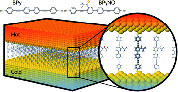
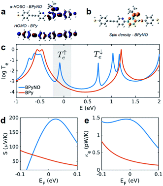
In this paper, we demonstrate that spin orbitals (SO) in nitroxide21 stable organic radicals can be used to design molecular structures with unprecedented thermoelectric efficiency. Fig. 1 shows the molecular structure of 2,2′-bipyridine (BPy) and 2,2′-bipyridine functionalized with tert-butyl nitroxide radical (BPyNO) cores connected to two thiobenzene anchors through acetylene linkers. BPyNO radicals have been demonstrated to be stable under ambient conditions with no decomposition for several months.21 In order to further enhance the stability of the molecular film formed by a massively parallel array of BPyNO, suitable encapsulation similar to that applied for 2D materials22 can be applied. BPy is a conjugated molecule and its highest occupied molecular orbital (HOMO) is extended over the molecule (Fig. 2a). The highest occupied spin orbital (HOSO) for majority spins of BPyNO is localized on the NO fragment and neighbouring phenyl ring (Fig. 2a). Spin density calculation (see Methods) reveals that this is due to the localization of majority spins on nitroxide radicals (Fig. 2b). Note that α-HOSO (highest occupied spin orbital), α-LUSO (lowest unoccupied spin orbital), β-HOSO and β-LUSO may be referred to also as spin-up HOMO, spin-up LUMO, spin-down HOMO and spin-down LUMO, respectively.To study transport properties of junctions formed by BPy and BPyNO between the gold electrodes, we obtain material specific mean-field Hamiltonians from the optimised geometry of junctions using density functional theory (DFT).23 We then combine the obtained Hamiltonians with our transport code7,24 to calculate the transmission coefficient7Te(E) for electrons traversing from the hot electrode to the cold one (Fig. 1) through BPy and BPyNO (see Computational methods). Te(E) is combined with the Landauer formula7 to obtain the electrical conductance. At low temperatures, the conductance G = G0Te(EF) where G0 is the quantum conductance and EF is the Fermi energy of the electrode. At room temperature, the electrical conductance is obtained by the thermal averaging of transmission coefficients calculated using the Fermi function (see Computational methods).
Fig. 2c shows the transmission coefficient Te(E) for electrons with energy E traversing through the BPy and BPyNO junctions. The red curve in Fig. 2c shows Te for BPy. The room temperature electrical conductance of the BPy junction is ca. 4 × 10⁻⁴G0 at DFT Fermi energy (E = 0 eV). The electron transport is mainly through the HOMO level because of the extended HOMO state (see Table S1 of the ESI†). Furthermore, due to the charge transport between sulphur atoms and gold electrodes, in molecular junctions formed by thiol anchors, transport occurs to be through the HOMO state.25 Since the electronic structure of BPyNO is spin polarised, we compute the total  from the transmission coefficient of majority (↑) and minority (↓) spins. The total Te of the BPyNO junction is shown by the blue curve in Fig. 2c. Clearly, two new resonances are formed in the HOMO–LUMO gap of the parent BPy. These new resonances are due to the majority (↑) and minority (↓) spin orbitals localised on the nitroxide radical (see the orbitals of BPyNO and BPy in the ESI†).
  and
and  for BPyNO radicals are shown in Fig. S1 of the ESI.†
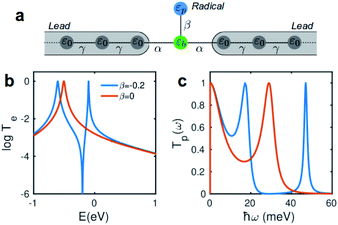
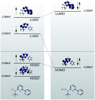
Due to quantum interference between the transmitted wave through the backbone and reflected wave by the singly occupied orbital of the pendant group, a Fano-resonance forms. This is shown by the simple tight-binding model in Fig. 3b. When a pendant orbital is attached to the one level system (Fig. 3a), two resonances are formed due to the backbone and pendant sites. The resonances are close to the energy levels of these orbitals. The resonance due to α-HOSO is close to EF in BPyNO (shown also with the grey region in Fig. 2c). The BPyNO radical has a tendency to gain (see Table S3 of the ESI†) an electron or share its electron (e.g. with a hydrogen atom to form –O–H) and minimize its energy. Fig. 4 shows the spin orbitals of the BPyNO molecular core and molecular orbitals of BPyNO with a hydrogen atom attached to oxygen to form the non-radical counterpart of BPyNO. When the hydrogen atom is detached from the core, the HOMO level of the non-radical BPyNO splits into two α-HOSO and β-LUSO states and moves up in energy.
The conductance of BPyNO is ca. 3 × 10⁻³G0 at DFT Fermi energy. Due to the new resonance transport through majority spins (see spin density plots in Fig. 2b), the conductance of BPyNO, on average, is about an order of magnitude higher than that of BPy around DFT Fermi energy. This is even higher closer to the resonance. This new resonance not only enhances the electrical conductance significantly, but also has a large effect on the room temperature Seebeck coefficient S (Fig. 2d). Note that S is proportional to the slope of the electron transmission coefficient Te evaluated at the Fermi energy (Sα∂![[thin space (1/6-em)]](https://www.rsc.org/images/entities/char_2009.gif) ln
ln![[thin space (1/6-em)]](https://www.rsc.org/images/entities/char_2009.gif) T(E)/∂E at E = EF).4,7 As a consequence of the sharp slope of α-HOSO resonance in BPyNO close to EF, the Seebeck coefficient increases 4 times compared to that of BPy and reaches high values of ca. +200 μV K−1 in BPyNO. The sign of S is positive as a consequence of HOSO dominated transport in BPyNO.26
T(E)/∂E at E = EF).4,7 As a consequence of the sharp slope of α-HOSO resonance in BPyNO close to EF, the Seebeck coefficient increases 4 times compared to that of BPy and reaches high values of ca. +200 μV K−1 in BPyNO. The sign of S is positive as a consequence of HOSO dominated transport in BPyNO.26
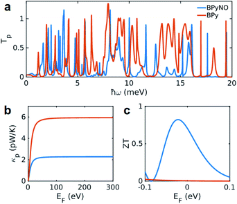
The heat is transmitted by both electrons and phonons.3Fig. 2e shows the thermal conductance due to electrons obtained from Te in Fig. 2c (see Computational methods). The heat transport due to electrons is higher in BPyNO but its absolute value is very low in the range of 0.6–1.5 pW K−1 compared to other molecular junctions.3,18 In order to calculate thermal conductance due to phonons, we use material specific ab initio calculation. We calculate the transmission coefficient7 of phonons Tp(ω) with energy ℏω traversing through BPy and BPyNO from one electrode to the other. The thermal conductance due to phonons (κp) then can be calculated from Tp(ω) using a Landauer like formula (see Computational methods).
Fig. 5a shows the phonon transmission coefficient Tp(ω) for BPy and BPyNO junctions. Clearly Tp is suppressed in BPyNO compared to that of BPy for two reasons. First, the nitroxide radical makes the molecule asymmetric. Secondly, it reflects transmitting phonons through the BPy backbone. Consequently, the width of the resonances decreases.7 This is also confirmed by the simple tight binding model in Fig. 3c. Furthermore, some of the vibrational modes are suppressed e.g. modes at 6 meV, 9.5 meV and 13 meV (see movies in the ESI† that show the visualization of modes at these frequencies for both BPy and BPyNO). These two effects combined lead to a 3 times lower phonon thermal conductance in BPyNO (Fig. 5b). Tp is suppressed in BPyNO such that the electron and phonon contributions to the thermal conductance become comparable. We obtain the total room temperature thermal conductance of ca. 4.5 pW K−1 in BPyNO. The thermal conductance is dominated mainly by phonons in BPy leading to a total room temperature thermal conductance of ca. 6 pW K−1. From the obtained G, S and κ, we can now compute the full thermoelectric figure of merit7ZT as shown in Fig. 5c. ZT enhances significantly in the nitroxide radical functionalized junction (blue curve in Fig. 5c) compared to that of the parent BPy (red curve in Fig. 5c). A room temperature ZT of ca. 0.8 is accessible in the BPyNO radical for a wide energy range in the vicinity of EF. This is 160 times higher than room temperature ZT = 0.005 of BPy at EF.
Molecules are expected to show a high Seebeck coefficient because they pose sharp transport resonance features, thanks to their well separated discrete energy levels. However, a relatively small Seebeck coefficient has been measured in molecules so far.3 Among them, C60 shows the highest Seebeck coefficient of about −18 μV K−1 to −20 μV K−4. This leads to a power factor in the range of 0.03 pW per molecule. There is no thermal conductance measurement of C60 but using the predicted value,27 a low room-temperature ZT of 0.1 is expected. The challenge in exploiting quantum interference in molecules for thermoelectricity lies in controlling the alignment of the molecular levels and moving quantum interference induced resonances close to the Fermi level of the electrodes. Resonance transport close to the Fermi level through spin orbitals that we propose is a generic feature of stable organic radicals which can be utilised to overcome this challenge and enhance the thermoelectric efficiency of molecular junctions. The massively parallel array of BPyNO in self-assembled monolayers can then be formed to create ultra-thin molecular films with high ZT to convert waste heat to electricity.
Conclusions
In this paper, we demonstrated for the first time that the thermoelectric figure of merit of junctions formed by the nitroxide stable radical enhances significantly from ca. 0.005 in the parent BPy to 0.8 in the daughter BPyNO. This enhancement is a generic feature of radicals because they create resonances close to the Fermi energy of the electrode. This ground breaking strategy can be utilized to design molecular junctions and ultra-thin film thermoelectric materials for efficient conversion of waste heat to electricity or on-chip cooling of CMOS-based technology in consumer electronic devices.Computational methods
Geometry optimization
The geometry of each structure studied in this paper was relaxed to a force tolerance of 10 meV Å−1 using the SIESTA23 implementation of density functional theory (DFT), with a double-ζ polarized basis set (DZP) and the Generalized Gradient Approximation (GGA) functional with Perdew–Burke–Ernzerhof (PBE) parameterization. A real-space grid was defined with an equivalent energy cut-off of 250 Ry. To calculate molecular orbitals and spin density of gas phase molecules, we employed an experimentally parameterised B3LYP functional using Gaussian g09v2 (ref. 28) with a 6-311++g basis set and tight convergence criteria.Electron transport
To calculate the electronic properties of the junctions, from the converged DFT calculation, the underlying mean-field Hamiltonian H was combined with our quantum transport code, Gollum.24 This yields the transmission coefficient Te(E) for electrons of energy E (passing from the source to the drain) via the relationship Te(E) = Tr(ΓeL(E)GRe(E)ΓeR(E)GR†e(E)) where ΓeL,R(E) = i(ΣeL,R(E) − Σe†L,R(E)) describes the level broadening due to the coupling between left L and right R electrodes and the central scattering region, ΣeL,R(E) is the retarded self-energy associated with this coupling and GRe = (ES − H − ΣeL − ΣeR)−1 is the retarded Green's function, where H is the Hamiltonian and S is the overlap matrix obtained from the SIESTA implementation of DFT. The DFT+Σ approach has been employed for spectral adjustment.7Phonon transport
Following the method described in ref. 7 and 8 a set of xyz coordinates were generated by displacing each atom from the relaxed xyz geometry in the positive and negative x, y and z directions with δq′ = 0.01 Å. The forces Fiq = (Fix, Fiy, Fiz) in three directions qi = (xi, yi, zi) on each atom were then calculated and used to construct the dynamical matrix where the mass matrix
  and
and  for i ≠ j were obtained from finite differences. To satisfy momentum conservation, the K for i = j (diagonal terms) is calculated from
  . The phonon transmission Tp(ω) then can be calculated from the relationship Tp(ω) = Trace(ΓpL(ω)GRp(ω)ΓpR(ω)GR†p(ω)) where ΓpL,R(ω) = i(ΣpL,R(ω) − Σp†L,R(ω)) describes the level broadening due to the coupling to the left L and right R electrodes, ΣpL,R(ω) is the retarded self-frequency associated with this coupling and GRp = (ω2I − D − ΣpL − ΣpR)−1 is the retarded Green's function, where D and I are the dynamical and the unit matrices, respectively. The phonon thermal conductance κp at temperature T is then calculated from
  where fBE(ω,T) = (eℏω/kBT − 1)−1 is the Bose–Einstein distribution function and ℏ is reduced Planck's constant and kB is Boltzmann's constant.
Thermoelectric properties
Using the approach explained in ref. 7, the electrical conductance G = G0L0, the electronic contribution of the thermal conductance κel = (L0L2 − L12)/hTL0 and the Seebeck coefficient S = −L1/eTL0 are calculated from the electron transmission coefficient Te(E) where the momentums and fFD is the Fermi–Dirac probability distribution function fFD = (e(E−EF)/kBT + 1) − 1, T is the temperature, EF is the Fermi energy, G0 = 2e2/h is the conductance quantum, e is the electron charge and h is Planck's constant. The full thermoelectric figure of merit ZT is then calculated using ZT(EF,T) = G(EF,T)S(EF,T)2T/κ(EF,T) where G(EF,T) is the electrical conductance, S(EF,T) is the Seebeck coefficient, and κ(EF,T) = κel(EF,T) + κph(T) is the thermal conductance due to the electrons and phonons.
Data availability
The input files to reproduce simulation data can be found at https://warwick.ac.uk/nanolab.Conflicts of interest
There are no conflicts to declare.Acknowledgements
H. S. acknowledges the UKRI for Future Leaders Fellowship no. MR/S015329/1. S. S. acknowledges the Leverhulme Trust for Early Career Fellowship no. ECF-2018-375.Notes and references
- A. Shehabi, S. J. Smith, D. Sartor, R. Brown, M. Herrlin, J. Koomey, E. Masanet, N. Horner, I. Azevedo and W. Lintner, Lawrence Berkeley Natl. Lab. Berkeley, CA, Tech. Rep., LBNL-1005775 Search PubMed.
- F. J. Disalvo, Science, 1999, 285, 703–706 CrossRef CAS PubMed.
- L. Cui, R. Miao, C. Jiang, E. Meyhofer and P. Reddy, J. Chem. Phys., 2017, 146, 092201 CrossRef.
- L. Rincón-García, C. Evangeli, G. Rubio-Bollinger and N. Agraït, Chem. Soc. Rev., 2016, 45, 4285–4306 RSC.
- G. J. Snyder and E. S. Toberer, Nat. Mater., 2008, 7, 105–114 CrossRef CAS PubMed.
- B. Russ, A. Glaudell, J. J. Urban, M. L. Chabinyc and R. A. Segalman, Nat. Rev. Mater., 2016, 1, 16050 CrossRef CAS.
- H. Sadeghi, Nanotechnology, 2018, 29, 373001 CrossRef PubMed.
- H. Sadeghi, S. Sangtarash and C. J. Lambert, Nano Lett., 2015, 15, 7467–7472 CrossRef CAS PubMed.
- N. Sergueev, S. Shin, M. Kaviany and B. Dunietz, Phys. Rev. B: Condens. Matter Mater. Phys., 2011, 83, 195415 CrossRef.
- M. Samadi, N. Sarikhani, M. Zirak, H. Zhang, H.-L. Zhang and A. Z. Moshfegh, Nanoscale Horiz., 2018, 3, 90–204 RSC.
- P. Luo, F. Zhuge, Q. Zhang, Y. Chen, L. Lv, Y. Huang, H. Li and T. Zhai, Nanoscale Horiz., 2019, 4, 26–51 RSC.
- L. E. Bell, Science, 2008, 321, 1457–1461 CrossRef CAS PubMed.
- A. Zevalkink, E. S. Toberer, W. G. Zeier, E. Flage-Larsen and G. J. Snyder, Energy Environ. Sci., 2011, 4, 510–518 RSC.
- E. Leary, B. Limburg, A. Alanazy, S. Sangtarash, I. Grace, K. Swada, L. J. Esdaile, M. Noori, M. T. González, G. Rubio-Bollinger, H. Sadeghi, A. Hodgson, N. Agraït, S. J. Higgins, C. J. Lambert, H. L. Anderson and R. J. Nichols, J. Am. Chem. Soc., 2018, 140, 12877–12883 CrossRef CAS PubMed.
- N. Algethami, H. Sadeghi, S. Sangtarash and C. J. Lambert, Nano Lett., 2018, 18, 4482–4486 CrossRef CAS PubMed.
- M. H. Garner, W. Bro-Jørgensen, P. D. Pedersen and G. C. Solomon, J. Phys. Chem. C, 2018, 122, 26777–26789 CrossRef CAS.
- X. Zhao, C. Huang, M. Gulcur, A. S. Batsanov, M. Baghernejad, W. Hong, M. R. Bryce and T. Wandlowski, Chem. Mater., 2013, 25, 4340–4347 CrossRef CAS.
- H. Sadeghi, J. Phys. Chem. C, 2019, 123, 12556–12562 CAS.
- P. Gehring, A. Harzheim, J. Spièce, Y. Sheng, G. Rogers, C. Evangeli, A. Mishra, B. J. Robinson, K. Porfyrakis, J. H. Warner, O. V. Kolosov, G. A. D. Briggs and J. A. Mol, Nano Lett., 2017, 17, 7055–7061 CrossRef CAS PubMed.
- R. G. Hicks, Org. Biomol. Chem., 2007, 5, 1321 RSC.
- K. Osanai, A. Okazawa, T. Nogami and T. Ishida, J. Am. Chem. Soc., 2006, 128, 14008–14009 CrossRef CAS PubMed.
- Q. Li, Y. Zhao, J. Guo, Q. Zhou, Q. Chen and J. Wang, Nanoscale, 2018, 10, 3799–3804 RSC.
- J. M. J. M. Soler, E. Artacho, J. D. Gale, A. García, J. Junquera, P. Ordejón and D. Sánchez-Portal, J. Phys.: Condens. Matter, 2002, 14, 2745–2779 CrossRef CAS.
- J. Ferrer, C. J. Lambert, V. M. García-Suárez, D. Z. Manrique, D. Visontai, L. Oroszlany, R. Rodríguez-Ferradás, I. Grace, S. W. D. Bailey, K. Gillemot, H. Sadeghi and L. A. Algharagholy, New J. Phys., 2014, 16, 093029 CrossRef.
- R. Stadler and K. W. Jacobsen, Phys. Rev. B: Condens. Matter Mater. Phys., 2006, 74, 161405 CrossRef.
- H. Sadeghi, Phys. Chem. Chem. Phys., 2019, 21, 2378–2381 RSC.
- J. C. Klöckner, R. Siebler, J. C. Cuevas and F. Pauly, Phys. Rev. B, 2017, 95, 245404 CrossRef.
- M. J. Frisch, Gaussian G9, 2016 Search PubMed.
Footnote |
| † Electronic supplementary information (ESI) available: Gas phase molecular orbital calculations. See DOI: 10.1039/c9na00649d |
| This journal is © The Royal Society of Chemistry 2020 |

