 Open Access Article
Nanostructured metal chalcogenides confined in hollow structures for promoting energy storage
Ying
Liu
,
Zhiwen
Che
 ,
Xuyun
Lu
 ,
Xiaosi
Zhou
 ,
Min
Han
 ,
Jianchun
Bao
 * and
Zhihui
Dai
 *
*
Jiangsu Collaborative Innovation Center of Biomedical Functional Materials, School of Chemistry and Materials Science, Nanjing Normal University, Nanjing 210023, P. R. China. E-mail: baojianchun@njnu.edu.cn; daizhihuii@njnu.edu.cn
First published on 26th December 2019
Abstract
The engineering of progressive nanostructures with subtle construction and abundant active sites is a key factor for the advance of highly efficient energy storage devices. Nanostructured metal chalcogenides confined in hollow structures possess abundant electroactive sites, more ions and electron pathways, and high local conductivity, as well as large interior free space in a quasi-closed structure, thus showing promising prospects for boosting energy-related applications. This review focuses on the most recent progress in the creation of diverse confined hollow metal chalcogenides (CHMCs), and their electrochemical applications. Particularly, by highlighting certain typical examples from these studies, a deep understanding of the formation mechanism of confined hollow structures and the decisive role of microstructure engineering in related performances are discussed and analyzed, aiming at prompting the nanoscale engineering and conceptual design of some advanced confined metal chalcogenide nanostructures. This will appeal to not only the chemistry-, energy-, and materials-related fields, but also environmental protection and nanotechnology, thus opening up new opportunities for applications of CHMCs in various fields, such as catalysis, adsorption and separation, and energy conversion and storage.
Introduction
Nanostructured metal chalcogenides (MCs) have drawn considerable attention during the past few decades owing to their rich redox chemistry, diverse crystal structures and high electrochemical activity.1–3 These virtues lead them to great achievements in energy storage systems, including lithium-ion batteries (LIBs), lithium–sulfur (Li–S) batteries, sodium-ion batteries (SIBs), supercapacitors, etc.4–8 Particularly, compared with the traditional intercalated LiMO2 cathodes (M = Mn, Ni, Co or their mixtures) of LIBs, MCs usually possess ameliorative electrochemical reversibility originating from their faster charge transfer kinetics, and higher theoretical specific capacities when used as electrode materials for batteries.9 For instance, FeS2 has a theoretical specific capacity of 894 mA h g−1 and MoS2 demonstrates a theoretical specific capacity of 670 mA h g−1, both of which are much higher than that of the LiMO2 cathodes (less than 200 mA h g−1).10 Moreover, MCs usually possess better electrical conductivity, thermal stability and mechanical stability than their corresponding metal oxides.11 Notwithstanding these virtues, the practical application of MCs is still confronted with some serious problems, such as the limited number of accessible active sites, unsatisfactory electrical conductivity, blocked ion and mass transmission channels, knotty shuttle effect of lithium/sodium polysulfides and pronounced volume variation during the discharge/charge process.To alleviate these problems, diverse strategies, such as microstructure and component modulating,12 heteroatom doping,13 and hybridization with conductive matrixes,14 have been developed. Among these methods, hybridization with conductive matrixes, such as graphene, carbon frameworks, metal foam and foil, is of extraordinary interest given its obvious promotion effects. Distinctively, compared with the open-ended graphene and metal foam/foil, quasi-closed hollow frameworks are more appealing because of their unique intrinsic features including distinguishable interior voids, low density, high loading capacity and high surface-to-volume ratio, as well as short mass- and charge-transport lengths, thus representing a promising avenue for mitigating the above-mentioned obstacles of MCs.15,16 In general, these nanostructured MCs are encapsulated within the interior space of well-defined hollow frameworks to form confined hollow MCs (CHMCs), the construction of which endows MCs with many new functionalities for various electrochemical systems. To be specific, the nano-sized building blocks of MCs can both offer extra available electroactive sites for energy storage, and improve the tap density of 3D hollow structures. Meanwhile, the hollow shell can ensure an augmented contact area between the electrolyte and electroactive materials, which is beneficial for the fast diffusion of ions/electrons. Besides, it can also act as a barrier to prevent the encapsulated electroactive nanoparticles (NPs) from aggregating and loss. As for the hollow cavity, it can effectively alleviate the pulverization and dissolution of electrode materials by accommodating the pronounced volume variation associated with repeated charging/discharging processes.17,18 These unique structural characteristics make CHMCs promising electrode materials for diverse energy storage devices, and laudable electrochemical performances in terms of rate capability, specific capacity and cycling stability are achieved.
To date, diverse CHMCs have been created, in which the interior confined MCs mainly exist in the forms of NPs19 or nanosheets (NSs),20 while the morphologies of the external shell can be nano/microspheres,21 polyhedrons,22 nanotubes,23 and even nanoflowers.24 Such multiformity makes CHMCs a charming research topic. In spite of these successes, the study of CHMCs is still in its infancy, and more advanced confined hollow nanostructures with multifunctional compositions and controlled configurations, and related mechanisms remain to be explored. Considering that previous reviews have reported diverse 2D or simple hollow structures of metal sulfides and oxides, and their energy-related applications,25–29 this review focuses on CHMCs and the correlation between CHMC structural features and their electrochemical behaviours, aiming at providing some insight into the design and synthesis of advanced CHMCs. The content of this review can be divided into three parts: firstly, we summarized the very recent progress in the smart architecture of CHMCs through compositional and geometrical manipulation. Secondly, we systematically discussed the effect of structural engineering on optimizing various electrochemical performances. Increasing the diversity of CHMCs in a designed manner is expected to bring more possibilities in modulating the properties of functional nanostructures for many applications. Lastly, some future investigations on novel CHMCs are proposed to tackle the current and prospective possible challenges.
Results and discussion
Synthesis and formation mechanism of confined hollow structures
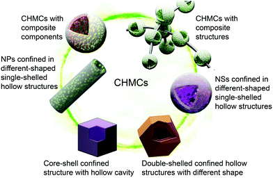
The CHMCs covered in this review mainly include sulfides of tin, iron, cobalt, nickel, molybdenum, and tungsten, and selenides of iron, cobalt, and molybdenum, as well as mixed metal sulfides or selenides. Based on their geometric architectures, subunits and chemical compositions, these CHMCs are classified into six categories: (1) double-shelled confined hollow structures with different shapes, such as nanoboxes and dodecahedral confined hollow structures, (2) core–shell confined structures with a hollow cavity, (3) hierarchical NP- and (4) NS-based confined structures encapsulated within different-shaped single-shelled hollow structures, (5) CHMCs with composite structures and (6) composite components (Fig. 1). Importantly, these CHMCs are basically obtained by combinatorial methods, in which a hard template method is firstly employed to establish reaction skeletons while a wealth of template-free methods, including those based on selective etching, ion exchange, Kirkendall effect and Ostwald ripening are subsequently adopted for the construction of the secondary structure. Besides, high temperature annealing is also often used for carbon framework production. Apart from the hard template method, a solvothermal strategy is usually adopted for the template-free synthesis of CHMCs.Double-shelled confined hollow structures with different shapes
Double or multi-shelled spherical hollow structures are the most common and available confined architectures adopted in electrochemical fields, but relevant reports are focused on metal oxides and hydroxides.30,31 Compared with metal oxides, MCs have a multitude of possible stoichiometric compositions, valence states, crystal structures and morphologies, the characteristics of which endow them with higher electrochemical activity.2 Thus there has recently been an increasing interest in fabricating MC-based confined hollow structures, and studies referenced herein are centred on non-spherical double-shelled CHMCs. Nevertheless, it is much more challenging to construct uniform polyhedral confined hollow structures due to the paucity of applicable anisotropic templates, difficulty in obtaining eligible coatings around high-curvature scaffolds, and poor preservation of shapes with high residual stress.2,32Although with great difficulties, several polyhedral CHMCs still have been successfully created by various ingenious approaches. For instance, hierarchical hollow nanoboxes of NiS with a double-shell have been obtained via a facile template-assisted method.33 As illustrated in Fig. 2a, Fe2O3 nanocubes with a uniform size of about 500 nm are firstly prepared as the initial template by a co-precipitation method. Then by means of a modified Stöber method, Fe2O3@SiO2 nanoboxes, in which the SiO2 coating is measured to be about 100 nm, are obtained. Afterwards, these core–shell nanoboxes are etched with HCl to remove the Fe2O3 cores. The obtained SiO2 hollow nanoboxes not only act as the hard template but also serve as the starting material for subsequent reactions. Concretely, they are hydrothermally treated in Ni2+-containing alkaline solution (100 °C, 12 h) to realize double-shelled nickel silicate (Ni3Si4O10(OH)2·5H2O) hollow nanoboxes. Note that the formation of double shells in this process is the result of the nanoscale Kirkendall effect. Because in the hydrothermal process, the silicate anions (originating from SiO2 dissolution) preferentially react with Ni2+ to form layered nickel silicate and deposit on the surface of SiO2 nanoboxes. As the reaction proceeds, SiO2 continuously dissolves and diffuses outwards, leading to a gap between the remaining SiO2 core and the nickel silicate shell. When the gap enlarges to a certain degree, the dissolved silicate anions would react with the inwardly diffused Ni2+. As a result, the second nickel silicate shell would form on the surface of the remaining SiO2 core. After 12 h of continuous reaction, double-shelled hollow nanostructures of nickel silicate are eventually obtained. This process basically does not change the cubic morphology of SiO2 nanoboxes except for a rougher surface. Finally, the as-prepared nickel silicate nanoboxes are chemically converted into double-shelled NiS hollow nanoboxes through a solution-based sulfidation reaction with Na2S. Fig. 2b–d display the TEM images of the resultant NiS nanoboxes, from which double-shelled hollow nanostructures with a well-defined pseudo-cubic void are clearly observed. The outer shell shows a similar morphological feature to that of the inner shell, with an obvious gap between them, meaning a unique box-in-box architecture. The thickness of the outer shell is measured to be around 50 nm (Fig. 2c), nearly identical to that of the inner shell. Moreover, both of the double shells are constructed by ultrathin and curved NSs with a small thickness of a few nanometers (Fig. 2d). Then, a high surface area of 140.28 m2 g−1 and small pore size below 10 nm are achieved for this double-shelled hollow nanobox of NiS. It is noteworthy that this template-assisted synthetic method can also be easily extended to the preparation of other double-shelled hollow metal sulfides, such as CuS (Fig. 2e and f) and MnS (Fig. 2g and h), signifying the universality of such a strategy.
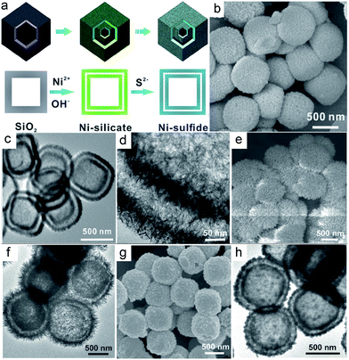 | ||
| Fig. 2 (a) Schematic illustration of the formation process of the nickel sulfide box-in-box hollow structure. (b) FESEM and (c and d) TEM image of the NiS box-in-box hollow structures. (e) FESEM and (f) TEM images of CuS box-in-box hollow structures. (g) FESEM and (h) TEM images of MnS box-in-box hollow structures. Reproduced from ref. 33, with permission from Wiley, 2014. | ||
Besides nanoboxes, complicated polyhedrons, such as dodecahedrons and some irregular ones have also been developed with the assistance of different polyhedron templates. For example, Lou's group synthesized a novel double-shelled zinc–cobalt sulfide (Zn-Co-S) rhombic dodecahedral cage (RDC) when a bimetallic zinc/cobalt-based zeolitic imidazolate framework (Zn/Co-ZIF) was employed as the rhombic dodecahedral hard template (Fig. 3a).34 Briefly, the Zn/Co-ZIF template (with a size of about 1.9 μm) is firstly subjected to selective chemical etching with tannic acid to generate yolk-shelled Zn/Co-ZIF RDCs. Afterwards, these yolk-shelled structures are transformed into the desired double-shelled Zn-Co-S RDCs (with a size of about 1.6 μm) via a solvothermal reaction with thioacetamide at 150 °C. The obtained double-shelled hollow nanostructure is similar to the above box-in-box hollow structure of NiS, but obviously, the synthesis of Zn-Co-S RDCs herein is more simple. This is mainly ascribed to their different etching mechanisms. Firstly, tannic acid is easily absorbed on the surface of Zn/Co-ZIF dodecahedrons and protects the dodecahedrons from destruction. Next, tannic acid can hardly penetrate into the body of Zn/Co-ZIF owing to its large molecular size. Consequently, such a surface-functionalized template would enable the selective etching of the unprotected interlayer of Zn/Co-ZIF dodecahedrons, thus contributing to the yolk-shelled Zn/Co-ZIF RDCs. Fig. 3b and c show the SEM images of the resultant Zn-Co-S RDCs, from which well-defined hollow dodecahedrons with double-shells (as revealed by the broken Zn-Co-S RDC shown in Fig. 3c) are clearly observed. The TEM images in Fig. 3d–f indicate that the inner and outer shells of the Zn-Co-S RDCs have a rhombic dodecahedral morphology, both of which are constructed by small NPs. According to energy-dispersive X-ray (EDX) analyses, the Zn/Co molar ratio in Zn-Co-S RDCs is about 0.6![[thin space (1/6-em)]](https://www.rsc.org/images/entities/char_2009.gif) :
:![[thin space (1/6-em)]](https://www.rsc.org/images/entities/char_2009.gif) 1. This value can be simply adjusted by changing the feeding ratio of zinc/cobalt nitrate in the synthesis of Zn/Co-ZIF dodecahedrons, while the related morphology is well maintained.
1. This value can be simply adjusted by changing the feeding ratio of zinc/cobalt nitrate in the synthesis of Zn/Co-ZIF dodecahedrons, while the related morphology is well maintained.
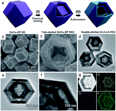 | ||
| Fig. 3 (a) Schematic illustration of the formation process of double-shelled Zn-Co-S RDCs. (b and c) FESEM, and (d–f) TEM images of the double-shelled Zn-Co-S RDCs. (g) HAADF-STEM image and elemental maps of Zn, Co, and S of a double-shelled Zn-Co-S RDC. Reproduced from ref. 34, with permission from Wiley, 2017. | ||
Core–shell confined structure with a hollow cavity
Besides the above double-shelled hollow structures with space between the shells, there are still some reports on core–shell hollow structures in which the shell is in close contact with the interior cavity.11,22 A carbonization process is usually involved in their synthesis. Taking the preparation of bullet-like Cu9S5@NC hollow NPs as an example, a combinatorial route, including the initial hard template method and subsequent ion exchange and carbonization treatments, is adopted.22 As illustrated in Fig. 4a, a bullet-like ZnO solid template was firstly prepared by a facile reflux method. Then by means of a facile anion exchange strategy, the above ZnO bullets were sulfurized to form ZnS hollow bullets. To improve the conductivity of the whole nanostructure, a layer of nitrogen-doped carbon shell was subsequently covered on the surface of ZnS to form the ZnS@NC nanostructure via coating with polydopamine (PDA) and then annealing at evaluated temperature. Finally, a cation exchange strategy between Zn2+ and Cu2+ was conducted to realize the construction of desired bullet-like Cu9S5@NC hollow nanostructures (Fig. 4b–d). Delightedly, such a self-templating method is also applicable for preparing Cu9S5 hollow particles with different shapes, such as hollow spheres, microboxes and nanotubes.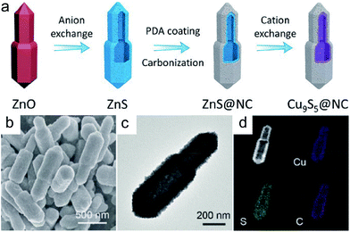 | ||
| Fig. 4 (a) Schematic illustration of the synthesis of bullet-like Cu9S5@NC hollow particles. (b) FESEM, (c) TEM, and (d) elemental mapping images of the Cu9S5@NC hollow bullet. Reproduced from ref. 22, with permission from Wiley, 2019. | ||
Nanoparticles confined in different-shaped single-shelled hollow structures
Apart from double-shelled confined hollow structures and core–shell confined structures with a hollow cavity, single-shelled hollow structures with diverse electroactive MC NPs embedded in their interior cavities have also been developed. For example, Yoon's group prepared a single-shelled hollow N-doped carbon (NC) sphere encompassing a millerite NiS core (denoted as NiS-NC HS).35Fig. 5a schematically illustrates the synthetic procedure of the NiS-NC HS, as well as its Ni3S2 and Ni3S2-NC counterparts. Briefly, the surface of the metallic Ni templates was firstly coated with a layer of polydopamine (PDA), followed by annealing carbonization to produce Ni-NC NPs. Subsequently, the Ni-NC NPs were partly etched with HCl to create confined Ni-NC HS. Note that a void space (between the NC shell and Ni core) was produced during the etching process, which plays a decisive role in subsequent preparation of the desired NiS-NC HS because appropriate void space can accommodate the volume expansion of the metallic Ni core during the sulfidation process. Otherwise, the NC shells would be broken, leading to a collapsed NC shell accompanied by an aggregated Ni3S2 core. Lastly, the above Ni-NC HS was sulfurated with thiourea to realize NiS-NC HS. In the absence of PDA coating and annealing, coalescing metallic-rich Ni3S2 NPs are obtained. This means both the envelope of the carbon shell and subsequent etching to release certain free space are necessary for preparing the unique NiS-NC HS.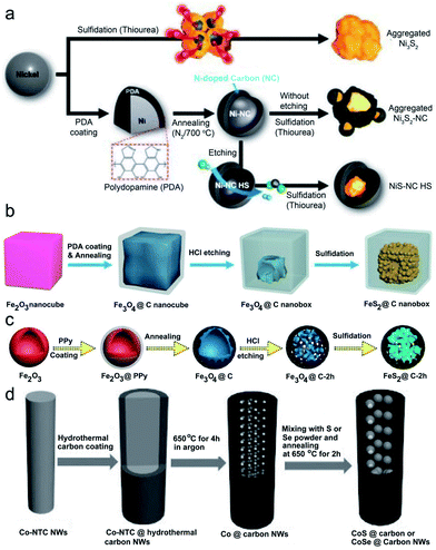 | ||
| Fig. 5 (a) Schematic illustration of the synthesis of NiS-NC HS in comparison to Ni3S2 and Ni3S2 NC. Reproduced from ref. 35, with permission from Wiley, 2018. (b) Schematic illustration of the synthesis of FeS2@C yolk–shell nanoboxes. Reproduced from ref. 36, with permission from the Royal Society of Chemistry, 2017. (c) Schematic illustration of the synthesis of peapod-like CoS⊂carbon NWs and CoSe⊂carbon NWs. Reproduced from ref. 37, with permission from the Royal Society of Chemistry, 2018. (d) Schematic illustration of the synthesis of peapod-like nanoarchitecture. Reproduced from ref. 38, with permission from Wiley, 2016. | ||
Encouragingly, similar synthetic routes, including the initial coating, annealing and subsequent etching, sulfidation or selenization, are also applicable for developing other different component MCs@carbon confined hollow structures. Taking the synthesis of FeS2@C yolk–shell nanoboxes as an example (Fig. 5b),36 Fe2O3 nanocubes are adopted as the initial template, and then after step-by-step coating, annealing and etching, Fe3O4@C nanoboxes are obtained. Such Fe3O4@C nanoboxes are finally transformed into the desired FeS2@C nanoboxes via an annealing sulfidation process with sulphur powder based on the reaction of Fe3O4 + 8S → 3FeS2 + 2SO2↑, which is different from the above case of NiS-NC HS. The latter is realized by means of a hydrothermal reaction with thiourea (Ni + H2S → NiS + H2↑, H2S originates from thiourea decomposition). Replacing the Fe2O3 nanocubes with Fe2O3 hollow spheres, Li et al. fabricated a different type of FeS2@C nanostructure with FeS2 NSs encapsulated in porous hollow carbon sphere (as displayed in Fig. 5c).37 The formation of FeS2 NSs is mainly attributed to the tiny size of the Fe3O4 intermediate and thus its ability to be easily vulcanized. Other than the FeS2@C, peapod-like carbon-encapsulated cobalt chalcogenide nanowires (CoS⊂carbon NWs and CoSe⊂carbon NWs) have also been successfully developed via the above method when cobalt-nitrilotriacetic acid (Co-NTC) NWs are selected as the hard template (Fig. 5d).38 Differently, during the annealing process, the carbon shell is pyrolyzed into amorphous carbon walls and coated on the surface of the initial Co-NTC NWs. Meanwhile, the NTC is pyrolyzed into low density porous carbon cores, and the Co ion is reduced into metal NPs which preferably embed into the porous carbon cores, finally offering peapod-like structured Co⊂carbon NWs. These metallic Co NPs are highly active, and thus would easily allow the permeation of S or Se powder through the carbon layers at high temperature to form the desired CoS⊂carbon and CoSe⊂carbon NWs. Obviously, this “top-down” synthesis approach is similar to the previously reported template-assisted method, but no extra etching step is needed, and thus is of great convenience for broad applications.
Besides nanospheres and nanopolyhedrons, nanotubes (especially carbon nanotubes) have also been frequently adopted as containers for improving the electrochemical performance of various materials. Furthermore, the 1D cavity of carbon nanotubes has been proposed as the nanoreactor for promoting different catalytic reactions (by introducing active materials into the cavity). However, there are few reports related to confined structures of CMs in carbon nanotubes. Apart from the above “top-down” synthetic method, several simple methods using carbon nanotubes as the nanoscale reactor have been developed to prepare CHMCs.40,41 Zhang and Liu's group adopted a solvothermal and subsequent heat treatment.39Fig. 6a depicts the detailed synthetic procedure of the Fe–S@CNT, which mainly includes (1) vapor deposition of sulfur/ferrocene into the hollow nanochannels of CNTs to form S-ferrocene@CNTs; (2) annealing in an inert atmosphere for producing Fe–S NPs inside the CNTs (Fe–S@CNTs). The CNTs herein are of great importance in stimulating the decomposition of ferrocene and subsequent sulfidation because the interior of CNTs has a strong affinity for the reactant molecules, creating a higher local concentration and pressure of reactants inside the CNT reactor than the open environment, and thus finally increases the reaction rate and yield. Besides, by means of a facile in situ chemical transformation, Sun's group designed a novel bamboo-like confined hollow structure with Fe1−xS NPs encapsulated within bamboo-like carbon nanotubes (Fe1−xS@CNTs).40 Importantly, these composites are cross-linked with each other to form a 3D network, which can serve as a conductive highway for rapid electron transportation. Fig. 6b shows the template-free formation process of the delicate Fe1−xS@CNTs. To be specific, a mixture of melamine and FeCl3, obtained from sustaining stirring at low temperature and mechanical grinding, was firstly pyrolyzed under an inert atmosphere to produce an Fe-based precursor. During this process, melamine was decomposed and the released C/N species liberally cracked on the surface of Fe particles (derived from FeCl3 decomposition), followed by diffusion into the particles to form the Fe3C/Fe@CNT composite. Moreover, numerous pores were generated under this process, contributing to a high surface area of 269.5 m2 g−1 and pore volume of 0.674 cm−3 g−1. Finally, the Fe3C/Fe@CNTs were in situ chemically converted to the Fe1−xS@CNTs composite by means of annealing with sulfur powder. Fig. 6c–f present the morphology and microstructure characteristics of the above Fe1−xS@CNTs, and a hollow bamboo-like morphology with a diameter of 20–50 nm was observed. Moreover, the encapsulated Fe1−xS NPs are highly dispersed throughout the CNTs (not limited to the end). Such a template-free synthetic approach will simplify the experimental procedures and omit the consequent treatment of removing the template.
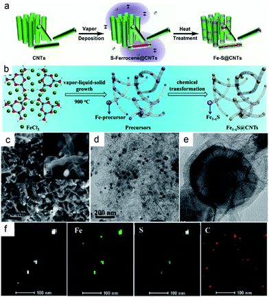 | ||
| Fig. 6 (a) Schematic illustration of the synthesis of Fe–S@CNT. Reproduced from ref. 39, with permission from Wiley, 2016. (b) Schematic illustration of the synthesis of Fe1−xS@CNTs. (c) SEM (d) TEM (e) HRTEM (f) STEM and corresponding elemental mapping images of the Fe1−xS@CNTs. Reproduced from ref. 40, with permission from American Chemical Society, 2017. | ||
Nanosheets confined in different-shaped single-shelled hollow structures
Recently, the synthesis of confined MCs NSs in different-shaped single-shelled hollow structures has become a hot research topic due to the unique structural virtues of 2D NSs, such as high specific surface area, short ion transport paths and rich physicochemical properties. For instance, Chen's group fabricated a novel confined hollow structure with petal-like MoS2 NSs embedded in hollow mesoporous carbon spheres (HMCSs) (denoted as MoS2@C).41Fig. 7 displays the multi-step synthetic route, in which tetraethylorthosilicate (TEOS) and resorcinol formaldehyde (RF) oligomers are firstly co-condensed on SiO2 particles to form the SiO2@SiO2/RF core–shell nanostructure (average size of 320 ± 30 nm). Secondly, these SiO2@SiO2/RFs are transformed into SiO2@SiO2/C nanospheres via calcination and carbonization. Thirdly, the SiO2 cores are chemically etched by NaOH to generate HMCSs. Lastly and most importantly, a hydrothermal method is employed to grow MoS2 NSs in the cavities of the HMCSs, in which process HMCSs play crucial roles in achieving the desired petal-like MoS2@C yolk–shell structure. Concretely, under hydrothermal conditions, thiourea can easily react with water to produce H2S gas, which tends to adsorb on the rough inner wall of HMCSs. Meanwhile, the MoO42− diffuses into the hollow cavity of HMCSs freely via the mesoporous shell. Upon the accumulation of H2S to a certain concentration, it would react with the interior MoO42−, leading to the formation of the MoS2 crystal nucleus inside the HMCSs. Afterwards, the HMCSs would act as nanoreactors to support the continuous confined growth of MoS2 NSs, and finally give rise to the petal-like MoS2@C. Note that if the mesoporous carbon shell is replaced by an ordinary one without mesoporous, the MoS2 NSs will directly grow on the outside surface of the carbon shell, which structure is easily broken during long-term cycling tests if applied in battery devices.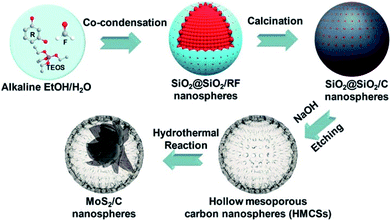 | ||
| Fig. 7 Schematic illustration of the synthesis of yolk–shell MoS2@C nanospheres. Reproduced from ref. 41, with permission from American Chemical Society, 2017. | ||
Delightedly, the above synthetic approach is also applicable for preparing other metal sulfides@carbon yolk–shell structures. As an example, replacing Na2MoO4·2H2O and thiourea with WCl6·2H2O and thioacetamide, hierarchical triple-shelled WS2–C–WS2 hollow nanospheres (denoted as HTSHNs WS2/C) with ultrathin WS2 NSs perpendicularly connected within the HMCS scaffold are obtained (Fig. 8).42 What's different is that the metal cations (W6+) herein are electrostatically adsorbed onto the HMCSs, followed by hydrolysis to form WOx nanocrystals dispersed inside and outside the carbon walls. Finally, these WOx nanocrystals are converted to WS2 NSs through the hydrothermal reaction with H2S. Besides metal sulfides, the above synthetic approach can also be applied to the construction of metal selenides. For example, Sun's group fabricated an encapsulated-type confined hollow structure comprising hollow carbon nanospheres (HCNSs) and few-layer MoSe2 NSs with expanded (002) planes.43 A mixture of selenium powder (Se) and hydrazine hydrate (N2H4H2O, 80%) is selected as the selenide precursor herein. The production of expanded (002) planes for MoSe2 is due to the intercalating effect (i.e., restricting the growth of MoSe2 NSs over certain planes) of ethylenediamine (H2N–CH2–CH2–NH2). Moreover, it also controls the 2D growth of MoSe2 in the hollow carbon shell frameworks to generate few-layer structures. As a result, the unique carbon-stabilized MoSe2@HCNS hybrid framework with expanded (002) crystal planes and few-layer MoSe2 NSs is realized.
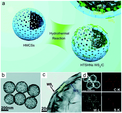 | ||
| Fig. 8 (a) Concept of synthesizing HTSHNs WS2/C. (b and c) TEM, (d) STEM and the corresponding EDX elemental maps of C, W, and S of HTSHNs WS2/C composites. Reproduced from ref. 42, with permission from the Royal Society of Chemistry, 2018. | ||
The above CHMCs with NSs inside are synthesized using the SiO2 template. Our group and the Lou group have recently developed a series of advanced structures with SnS2 NSs confined within different-shaped hollow carbon shells by simply changing the template adopted.20 As displayed in Fig. 9, uniform MnOx nanorods, Fe2O3 nanocubes, and SiO2 nanospheres are employed as the initial templates. Then by means of a simple solvothermal reaction, a layer of SnO2 nanocrystals is grown on their surface to form the core–shell structured MnOx@SnO2 nanorods, Fe2O3@SnO2 nanocubes, and SiO2@SnO2 nanospheres, Subsequently, dopamine polymerization (to form polydopamine PDA) is carried out on the surface of the above core–shell nanostructures, followed by selective etching with oxalic acid to produce SnO2@PDA hollow structures. Note that NaOH can etch PDA, and thus the SiO2 cores in the SiO2@SnO2 nanospheres are firstly removed with NaOH, and next, PDA coating is conducted. Afterwards, the above SnO2@PDA hollow structures are annealed at 500 °C under an Ar atmosphere to generate well-crystallized SnO2@C nanotubes, nanoboxes, and hollow nanospheres, respectively. Finally, these SnO2@C nanostructures are sulfurized at 350 °C under an H2S/Ar atmosphere to achieve the desired SnS2@CNTs, SnS2@CNBs, and SnS2@CNSs, respectively. Such a general templating strategy can also be extended to many other similar MCs for catalysis or energy related applications.
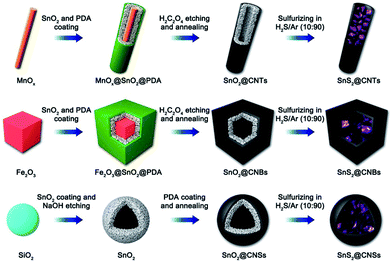 | ||
| Fig. 9 Schematic illustration of the synthesis processes of SnS2@CNTs, SnS2@CNBs, and SnS2@CNSs. Reproduced from ref. 20, with permission from Elsevier, 2018. | ||
Distinctively, by means of a well-designed template-free solvothermal method and carbonization treatment, Jiao and Feng's group created a porous hierarchical structure of Co9S8@carbon hollow microspheres (Co9S8@CHSs).44Fig. 10 shows the detailed template-free preparation procedure of the Co9S8@CHSs, which mainly includes the production of Co9S8@C precursor microspheres with hierarchical hollow structures, and subsequent transformation to the desired Co9S8@CHSs. Specifically, in the solvothermal system with glucose, thiourea and Co2+ dispersed in mixed solvent (EG and DMF), plenty of microspheres covered with flimsy carbon layers were firstly formed within a very short time and some of them evolved into core–shell structures when the reaction proceeds to about 1 h. Increasing the reaction time to 2 h, a folded carbon layer emerged which covered the surface of the spheres, and the spheres changed from core–shell to hollow structure. With the prolongation of reaction time, the thickness of the carbon layer increases gradually and the hollow structure has been formed completely after 6 h. Obviously, the generation of the hollow structure of Co9S8@CHSs should be ascribed to the Kirkendall effect. Such a template-free hydrothermal strategy is simple, environment-friendly and easy to operate, and thus is advantageous for advancing a wealth of other confined hollow structures of MCs. For instance, Qian and Zhu's group employed such a strategy for preparing MoS2@C hollow nanotubes.23 Briefly, the Mo3O10(C2H10N2) nanowire was firstly fabricated consulting the reported method, and then it was hydrothermally sulfurated to realize the desired MoS2@C hollow nanotube in the presence of glucose. When the reaction time proceeds to 2 h, some NSs emerged on the surface of the initial nanowires and amorphous carbon formed synchronically. As the time expands to 8 h, the central part of the initial nanowire becomes transparent, suggesting the transformation of Mo3O10(C2H10N2) to MoS2. Such conversion is basically completed until the reaction time achieves 12 h, accompanied by the generation of the carbon shell originating from glucose carbonization. These results indicate that the formation of the hollow structure should also be ascribed to the Kirkendall effect, in which process MoS2 is formed based on the continuous consumption of MoO3. Notably, it was found that, in the absence of glucose, MoS2 microflowers (rather than nanotubes) comprised of aggregated MoS2 NSs, are obtained. The main reason is that carbon takes shape along with the formation of MoS2 NSs, and the formed carbon shell can maintain the tubular-like morphology of MoS2 during the subsequent sulfuration process. This explanation is consistent with the formation of the above Co9S8@CHSs, i.e., without the tubular carbon shell to fix the shape, spherical nanostructures are obtained.
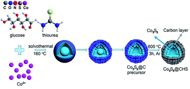 | ||
| Fig. 10 Schematic diagram of the synthesis route for Co9S8@CHSs. Reproduced from ref. 44, with permission from American Chemical Society, 2019. | ||
CHMCS with composite structures
Increasing the structural diversity of CHMCs can improve or even change the electrochemical behaviors of the resultant composite materials owing to the advantages and synergetic effects of different microstructures themselves.45 Generally, the structural diversification units can be 1D nanowires/nanotubes, 2D NSs or 3D nanoframes/skeletons. For example, Jin and co-workers developed a sulfur host material in which Co3S4 nanoboxes are connected in series by 1D CNTs, forming an integrated conductive network (S@CNTs/Co3S4-NBs).46 Such implant structure will boost the electrical conductivity of the sulfur species encapsulated in Co3S4-NBs, thus greatly enhancing the utilization rate of sulfur species. Fig. 11a presents the self-template synthetic process of the S@CNTs/Co3S4-NBs with three steps. Firstly, uniform ZIF-67 nanocubes were in situ nucleated, grown and threaded on carboxyl group (–COOH) functionalized CNTs to produce the CNTs/ZIF-67 precursor. Afterwards, this precursor was chemically converted to CNTs/Co3S4-NBs by means of solvothermal sulfuration and subsequent annealing treatments. Herein, a Kirkendall effect is responsible for the formation of hollow Co3S4-NBs due to the different diffusion rates of cobalt and sulfur species. Finally, a melt-diffusion method is employed to enrich the interior cavity of the above Co3S4-NBs with sulfur, leading to the desired S@CNTs/Co3S4-NB composite. In addition to this 1D CNT connected composite structure, Wang et al. fabricated a graphene sandwiched composite with SnS@C nanospheres intercalated in 2D graphene lamella (SnS@C-rGO), forming a honeycomb-like network architecture.47 The SnS@C nanospheres herein are constructed from nanoscale SnS NSs and hollow mesoporous carbon spheres, which could enable fast ion transport kinetics arising from decreased diffusion pathways. Moreover, their interconnected framework could enhance the electrical conductivity of the whole electrode. Fig. 11b reveals the formation process of the SnS@C-rGO composite, which is similar to that of the above petal-like MoS2@C structure, but the resultant yolk–shell nanospheres are further confined within GO NSs, followed by calcination to realize the desired SnS@C-rGO nanocomposite.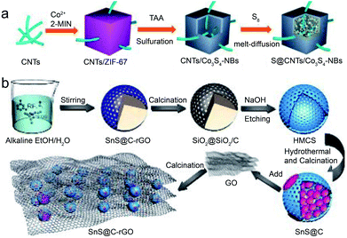 | ||
| Fig. 11 Schematic illustration of the synthesis of (a) S@CNTs/Co3S4-NBs. Reproduced from ref. 46, with permission from American Chemical Society, 2017. (b) Schematic illustration of the synthesis of the 3D SnS@C-rGO nanocomposite. Reproduced from ref. 47, with permission from Wiley, 2019. | ||
Besides, Sun and Wu's group developed a more complicated composite consisting of cobalt sulfide quantum dots (Co9S8 QDs with size less than 4 nm), mesoporous hollow carbon polyhedral (HCP) and 3D reduced graphene oxide (rGO) nanoframes to form a hierarchical sponge-like architecture.48 Specifically, the Co9S8 QDs are homogeneously embedded in the HCP matrix, which is further encapsulated in the macropores of the 3D rGO framework, forming a double carbon-confined hierarchical composite. Such a composite has colorful structural characteristics: (1) the HCP can prevent the excessive growth and aggregation of Co9S8 QDs, as well as expanding their lattice parameters for enhanced reactivity; (2) the rGO skeleton and HCP can provide double confinement for fixing and dispersing the host Co9S8 QDs; (3) such an integrated composite enables rapid electron transfer and prevents the additional capacity originated from the conductive agents. Obviously, this (Co9S8 QD@HCP) @rGO composite has extraordinary traits for energy storage systems compared with conventional Co9S8@C or Co9S8-C materials. Fig. 12 illustrates the ice-template-assisted combinatorial synthesis procedure of the (Co9S8 QD@HCP) @rGO composite, which mainly includes three steps: firstly, positively charged Co2+ was adsorbed onto the surface of negatively charged GO through electrostatic interactions. Then 2-methylimidazole was added and in situ grown to form a Co-based zeolitic imidazolate framework (ZIF-67) crystal on the surface of GO (ZIF-67@GO). Secondly, such a ZIF-67@GO suspension was frozen at −15 °C to obtain an ice crystal, followed by freeze drying to generate the ZIF-67@GO sponge-like precursor. The formation of the 3D scaffold sponge structure is the result of the removal of residual water molecules by high vacuum sublimation while the ice crystal acts as the template. Thirdly, after a simultaneous thermal reduction, carbonization and sulfidation of the above precursor, desired sponge-like (Co9S8 QD@HCP) @rGO composites are created. During this annealing process, the central cobalt ions and organic ligands from ZIF-67 were converted into Co9S8 QDs and HCP, respectively, while the GO was reduced to macroporous 3D rGO.
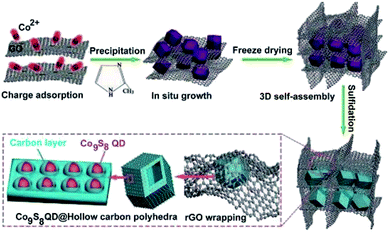 | ||
| Fig. 12 Schematic illustration of the fabrication procedure of (Co9S8 QD@HCP) @rGO sponge-like composites. Reproduced from ref. 48, with permission from Wiley, 2017. | ||
CHMCS with composite components
In order to meet some special needs for catalysis or energy systems, the rational design and construction of multi-component confined hollow structures comprising two or more reactive components with individual characteristics are desired.45 For example, ZnSe is a promising anode material for LIBs/SIBs owing to its high theoretical capacities and the abundance of zinc. However, the low electronic conductivity and enormous volume variation (during the charge–discharge process) of ZnSe make its application a great challenge. As a typical layered metal chalcogenide, MoSe2 has exhibited favorable performance for energy storage devices thanks to its large interlayer spacing (0.65 nm) and higher electrical conductivity. Therefore, the combination of ZnSe and MoSe is of great possibility for overcoming the drawbacks of the individual component and achieving commendable electrochemical performances. Chen and Qian's group has recently prepared a multi-component confined hollow structure with few-layered MoSe2 NSs and ultra-small ZnSe NPs homogeneously confined in a porous carbon matrix.18 The MoSe2 NSs herein are grown uniformly around the ZnSe NPs. Fig. 13a displays the template-free synthetic procedure of the above advanced ZnSe/MoSe2@C structure. To be specific, Keggin-type heteropolyanions (POMs) and H3PMo12O40 (PMA) (used as the Mo precursor) were firstly embedded into the customized cavities of ZIF-8 (serving as the Zn precursor) to form polymetallic MOFs via a self-assembly process. Then, by means of a facile annealing selenization strategy, few-layer MoSe2 NSs were grown around the ZnSe NPs, both of which were confined within the hollow porous carbon spheres, forming the desired ZnSe/MoSe2@C structure. In this step, Zn2+ clusters react with Se powder to form ZnSe NPs while the Mo species is reduced synchronously to form laminar MoSe2. The generation of the interior hollow architecture is ascribed to the utilization of PMA as the guest and the removal of excess organic solvent molecules during the selenization process. Other than the above hybrid nanostructure composed of two sole MCs, confined bimetallic or multi-MCs can also function well in various electrochemical fields due to the synergistic effect between different metal atoms. As an example, Li et al. synthesized a hollow bimetallic sulfide nanosphere assembled from NiCo2S4 NPs embedded in ultrathin carbon NSs (NiCo2S4@C HNSs).49Fig. 13b illustrates the detailed preparation process, which mainly includes the initial template-assisted precipitation of the NiCo precursor and subsequent in situ chemical conversion to NiCo2S4. Concretely, monodisperse SiO2 nanospheres were firstly activated in alkaline urea solution. Then under high-temperature hydrothermal conditions, the interfacial reaction between activated SiO2 and different metal ions occurs, leading to the formation and deposition of Ni2/3Co4/3(CO3)(OH)2 NSs around SiO2. Meanwhile, glucose is incorporated into carbon NSs, forming an interconnected NS-assembled shell which is uniformly coated on the SiO2 surface. Afterwards, this carbon shell is graphitized via calcination in Ar to create the NiCo-precursor@C@SiO2 nanostructure. Lastly and importantly, by means of a sulfurization reaction with Na2S, the above NiCo-precursor@C@SiO2 material is chemically converted into NiCo2S4@C hollow nanospheres. The production of the hollow cavity is ascribed to the etching of the SiO2 core by OH− released from S2− hydrolysis. Moreover, along with the phase conversion from the NiCo-precursor into NiCo2S4, its structure transforms from NSs into scattered NPs due to the anion exchange reaction (Kirkendall effect) during the sulfurization reaction with continuous outward ion diffusion. Remarkably, benefiting from the in situ template removal strategy, the obtained NiCo2S4@C HNSs show uniform size, abundant mesopores and robust structure. Besides, the design of carbon NSs may also favor the structural stability, for that the connected carbon NS assembly can relieve the collapse of the hollow structures during the template removal process. These merits endow the NiCo2S4@C HNSs with remarkable advantages for application in electrochemical systems.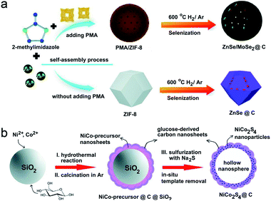 | ||
| Fig. 13 (a) Schematic synthesis of ZnSe/MoSe2@C and ZnSe@C nanocomposites. Reproduced from ref. 18, with permission from the Royal Society of Chemistry, 2019. (b) Schematic synthesis of NiCo2S4@C HNSs. Reproduced from ref. 49, with permission from the Royal Society of Chemistry, 2017. | ||
Apart from the above hybrid nanostructures and binary metal sulfides/selenides, doping of a small quantity of metal ions is also appealing for improving the electron transport, rate capability and cycle life of the resultant electrode materials. Typically, Lou et al. synthesized hierarchical Cu-doped CoSe2 microboxes constructed by ultrathin NSs via a facile two-step sequential ion exchange method.13Fig. 14a schematically illustrates the formation process of the Cu-doped CoSe2 microboxes, and Co–Co Prussian blue analogue (PBA) microcubes, prepared by a precipitation method, are selected as the starting material. Then, by means of an anion-exchange reaction with Se2− ions, Co–Co PBA was transformed into hierarchical CoSe2 microboxes assembled from ultrathin NSs. Finally, a cation-exchange approach was conducted to achieve the doping of Cu2+ into CoSe2 microboxes. Besides, Wang and Qin's group fabricated a porous bamboo-like hollow tube composed of N-doped-C and MoS2 layers aligned vertically in an alternating sequence (MoS2/N-doped-C).50Fig. 14b illustrates the synthetic process, which mainly includes (1) the fabrication of MoS2/oleylamine (OAm) tubes by a solvothermal method and (2) further annealing transformation to MoS2/N-doped-C. In the solvothermal process, MoO3 (Mo precursor) firstly reacted with S2− (released from S powder) to generate MoS2, and OAm intercalated into the interspaces of MoS2 layers synchronously. Such an organic/inorganic hybrid tube is formed based on a new formation mechanism, and ethanol/water mixed solvent and OAm additive play key roles in this process. In the presence of pure ethanol or water, only irregular particles were obtained, while in the absence of OAm, no tube structure was observed. Water may change the polarity of ethanol, then affects the process of OAm-capping primary MoS2 monolayers and finally leads to the self-assembly of tubes. OAm serves as both the capping agent to intercalate between MoS2 layers/encapsulate monolayer MoS2, and the N-doped-carbon source for subsequent conversion of MoS2/OAm to MoS2/N doped-C tubes through annealing.
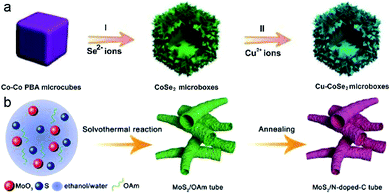 | ||
| Fig. 14 (a) Schematic synthesis of Cu–CoSe2 microboxes with two-step ion-exchange reactions. Reproduced from ref. 13, with permission from Wiley, 2018. (b) Schematic synthesis of MoS2/N-doped-C tube. Reproduced from ref. 50, with permission from Wiley, 2018. | ||
Table 1 summarizes the synthetic route, template and formation principle of diverse CHMCs reported in recent years, some of which representative works have been introduced and analyzed in detail above. By classification and comparison, it is found that the synthetic routes mainly include the hydrothermal process, ion exchange, sulfidation/selenization, surface coating, annealing carbonization, chemical etching, etc., in which the etching is usually realized with HF, NaOH, HCl, oxalic acid or OH− released from the hydrolysis of sulfide ions. Oxides (such as Cu2O, Fe2O3, and SiO2), MOF, metallic Ni, carbon sphere/tube, and some metal complexes are mostly adopted as templates to prepare confined hollow structures with different morphologies. Moreover, besides the etching methods, the interior void is basically achieved based on the principles of (1) Kirkendall effect, (2) Ostwald ripening, (3) galvanic replacement, (4) chemical etching, (5) solid-state decomposition and (6) dissolution–recrystallization. The construction of precursors, development of new templates, and control of reaction kinetics are of great importance for developing new synthetic strategies and novel CHMCs.
| Types of materials | Component | Template | Synthesis route | Interior void formation principle | Reference |
|---|---|---|---|---|---|
| Double-shelled nanobox | CuS@CoS2 NS | Cu2O, Co(OH)2 | Sulfidation and etching | Etching with Na2S2O3 solution | 7 |
| Double-shelled dodecahedral cage | Zn-Co-S | Zn/Co-ZIF rhombic dodecahedron | Sequential chemical etching and hydrothermal sulfurization | Etching with tannic acid | 34 |
| Double-shelled hollow structure | CoS NPs/CoS NS | ZIF-67 nanocube | Sequential modulation of template-assisted reactions of ZIF-67 with water and Na2S | Kirkendall effect | 6 |
| Box-in-box hollow structure | MS (M: Ni, Cu, Mn) NSs | Fe2O3 nanobox | Hydrolysis and sulfidation | SiO2 dissolving partially | 33 |
| Bullet-like hollow nanostructure | Cu9S5@NC | Bullet-like ZnO particle | Ion exchange and PDA coating and carbonization | Diffusion effect | 22 |
| Double-shelled hollow sphere | Nitrogen-doped double-shelled hollow carbon spheres-sulfur hybrid | TiO2 hollow sphere | Carbonization, etching and melt infiltration | Etching with HF | 17 |
| Hollow NPs embedded in a nanocage | Co9S8⊂C | ZIF-67 rhombic dodecahedral nanocrystal | Annealing and sulfidation | Kirkendall effect | 51 |
| “Brain-coral-like” mesoporous hollow confined structure | CoS2@N-doped C | ZIF-67 hollow sphere | Room-temperature solution method, carbonization, sulfidation and etching | Removal of cobalt by HCl etching | 52 |
| Yolk–shell nanobox | FeS2@C | Fe2O3 nanocube | Annealing, etching and sulfidation | Etching with HCl | 36 |
| NP inlaid hollow nanopolyhedron | Co9S8/C–S | ZIF-67 nanopolyhedron | Sulfidation annealing, and sulfur impregnation | Kirkendall effect | 4 |
| Nanodots confined within a porous network | ZnSe@N-doped carbon | Rhombic dodecahedral ZIF-8 | Pyrolysis and selenization | Pyrolysis and carbonization | 53 |
| NSs in a hollow nanostructure | SnS2@CNT; SnS2@CNB; SnS2@CNS | MnOx nanorod; Fe2O3 nanocube; SiO2 nanosphere | Hydrothermal treatment, annealing and sulfurization | H2C2O4 etching; NaOH etching | 20 |
| NSs confined in a hollow nanosphere | MoSe2@C | SiO2@SiO2/C | Hydrothermal treatment and confined growth of MoSe2 in a nanoreactor and etching | Etching with NaOH | 43 |
| NSs@hollow mesoporous sphere | SnS@C-rGO | SiO2@SiO2/RF | Hydrothermal treatment, calcination and etching | Etching with NaOH | 47 |
| NSs@3D porous sphere | FeS2@C | Hollow Fe2O3 nanosphere | Annealing, etching and sulfidation | — | 37 |
| Petal-like NSs in hollow mesoporous spheres | MoS2/C | SiO2@SiO2/RF nanosphere | Calcination, hydrothermal treatment and etching | Etching with NaOH | 41 |
| Hybrid nanobox | CoSe@C | ZIF-67 nanocube | Annealing and selenization | Diffusion effect | 54 |
| Core–hollow shell structure | NiS–C | Metallic Ni | Annealing, sulfidation and etching | Etching with HCl | 35 |
| Coconut-like core/shell hollow nanosphere | SnS/C | SnO2 hollow nanosphere | Micro-evaporation-plating and annealing/sulfidation and etching | Etching with NaOH | 55 |
| Sheet-on-sheet structured hollow nanosphere | MoS2/C | — | Polymerization of dopamine hydrochloride with Mo7O246− assisted by metal chelation and sulfuration | Tuning volume ratio of ethanol–water | 56 |
| A triple shell structure: NSs vertically embedded in a hollow mesoporous sphere | WS2–C | Hollow mesoporous carbon sphere | Hydrothermal treatment | — | 42 |
| Hierarchical nanostructures@hollow microsphere | Co9S8@C | — | Hydrothermal treatment and carbonization | Kirkendall effect | 44 |
| NPs distributed on a 3D hollow sphere | NiS@C | SiO2 nanosphere | Annealing, sulfidation and etching | Etching with OH− released from the hydrolysis of sulfide ions | 21 |
| 3D porous interconnected nanostructure | SnS/C | Sn2+–L-cysteine complex | Electrostatic spray deposition and annealing | — | 57 |
| Hollow heterostructure | Co3S4@MoS2 | ZIF-67 polyhedron | Two-step temperature-assisted hydrothermal synthesis and annealing | Diffusion effect | 58 |
| Hierarchical nanotubes constructed by NSs | SnS@C | MoO3 nanorod | Solvothermal treament, annealing and etching | Etching with ammonia | 59 |
| NPs confined within a hollow porous sphere | ZnSe/MoSe2@C | PMA/ZIF-8 | Self-assembly, calcination and selenization | Removal of excess organic solvent molecule | 18 |
| Nanocomposite confined in a hollow sphere | NiCo2(SxSe1−x)5/graphitic carbon | NiCo-MOF microsphere | Hydrothermal treatment, calcination and sulfidation/selenization | Solid-state decomposition | 60 |
| Hollow polyhedron hybrid | NiCo-LDH/Co9S8 (LDH: layered double hydroxide) | ZIF-67 | Annealing, hydrothermal treatment and sulfurization | Calcination treatment | 61 |
| Hierarchical core–shell nanocubes with hollow structure | CoS2/C@SnS2 | Co-MOF nanocube | Hydrothermal treatment | Anion exchange | 11 |
| Hollow sandwich structure | C–MoS2–C | Gibbsite | Hydrothermal and calcination | Etching with HCl | 62 |
| Sandwich-like three-layered hierarchical nanotube | TiO2@C@MoS2 | MnO2 nanowire | Annealing, hydrothermal treatment and etching | Acid etching | 63 |
| Cluster in a nanotube | Na2Se@SWCNT | — | Theoretical study | — | 64 |
| Peapod-like nanowire | CoS⊂C, CoSe⊂C | Cobalt-nitrilotriacetic acid nanowire | Hydrothermal, annealing and sulfuration | Porous carbon | 38 |
| Bamboo-like hollow tube | MoS2/N-doped C | MoS2/oleylamine tube | Hydrothermal and sulfuration | Self-assembly of tube in the mixed solvent (ethanol/water) | 65 |
| NPs encapsulated in a nanotube | Fe1−xS@C nanotubes | — | In situ solid-state approach, including pyrolysis and sulfidation | Vapor–liquid–solid mechanism | 40 |
| NPs encapsulated in a nanotube | Fe–S@CNTs | Carbon nanotube | Vapor deposition | — | 19 |
| NPs encapsulated in a nanotube | FeS2@C nanotube | Carbon nanotube | Annealing and sulfidation | — | 66 |
| Nanotube composite | MoS2@C | Mo3O10(C2H10N2) nanowire | Hydrothermal treatment sulfuration and carbonization | Kirkendall effect | 23 |
| Interlaced nanotube threaded hollow nanobox | Co3S4–C | Carbon nanotubes/ZF-67 | Solvothermal sulfuration and thermal annealing | Kirkendall effect | 46 |
| Confined NPs on a carbon nanotube network | CNT/CoS@C | — | Sulfidation and carbonization | Dissolution–recrystallization and Ostwald ripening | 67 |
| Hollow hybrid | SnO2/SnS2 | SnO2 hollow sphere | Two-step hydrothermal treatment | — | 68 |
| Hybrid hollow architecture | ZnS nanorods rooted in the porous carbon polyhedron | ZIF-8 polyhedron | Sulfidation and carbonization | Solid-state decomposition | 69 |
| Hollow nanosphere assembled from ultrathin NSs | NiCo2S4@C | SiO2 | Hydrothermal treatment, calcination, sulfidation and etching | Etching with OH− released from the hydrolysis of sulfide ions | 49 |
| Sponge-like composite | (Co9S8 quantum dots@hollow carbon polyhedral)@rGO | ZIF-67@GO | Thermal reduction, carbonization, and sulfidation | Carbonization of the organic ligands | 48 |
| Hollow sphere | S/C | SiO2 | Hydrothermal treatment, ball milling, carbonization and etching | Etching with HF | 70 |
| Hollow hybrid | Hollow CoS@porous carbon polyhedral/carbon nanotube | Co-based ZIF-67 template | Annealing and sulfidation | In situ carbonization | 71 |
| Hollow prism | M-MoS3 (M: Co, Ni) | M acetate hydroxide prism, Co-glycerate sphere, and ZIF-67 polyhedron | Precipitation, annealing | Outward flow of M2+ consuming the core template | 72 |
| Nanodots in a porous nanowire | FeS nanodots⊂porous graphitic carbon nanowire | — | Electrospinning technique, annealing and hydrothermal treatment | Graphitization of the amorphous carbon resulting in the formation of pores | 73 |
| Composite encapsulated in a hollow cube | NiCo2S4@nitrogen-doped carbon cube | Ni3[Co(CN)6]2@polydopamine nanocube | Self-polymerization, pyrolysis and vulcanization | — | 74 |
| Pistachio-shuck-like core/shell nanostructure | MoSe2/C | — | Reaction under high temperature and inert atmosphere | — | 3 |
| “Ship in a bottle” nanostructure | CoS2/C | Ketjen Black EC600JD carbon | Co2+ impregnation | — | 75 |
Applications in electrochemical energy storage and conversion
Among diverse alternatives, including MCs, metal oxides, Li-alloys (Si, Sn, Ge, Sb), etc., MCs are extraordinarily appealing because of their similar layered structure to graphite but superior capacity. For example, MoS2, a representative two-dimensional (2D) layer material, has a higher theoretical capacity of 669 mA h g−1. Nevertheless, the practical applications of these MCs are still hampered by the huge volume expansion and contraction during lithiation and delithiation processes, which will subsequently lead to (1) the pulverization and run away of the active component; (2) loss of electrical contact between the active component and conductive matrix; (3) production of a thick and insulating solid electrolyte interphase (SEI). Consequently, rapid capacity fading occurs for these anode materials. Besides, the limited electrical conductivity of MCs also blocks their further progress.
The rational engineering of advanced CHMCs is one possible solution to circumvent these issues (Fig. 15). For example, Lou's group developed a confined nanobox with a CoSe-enriched inner shell and an amorphous carbon-enriched outer shell (CoSe@carbon), using a template-assisted strategy.54 When evaluated as anode materials for LIBs, these unique CoSe@carbon nanoboxes manifest decent lithium-storage performance in terms of high specific capacity, exceptional rate capability, and excellent cycling stability (Fig. 16a–c). Moreover, this confined nanobox shows a high initial coulombic efficiency of 78.3% with small irreversible capacity loss during the first discharge/charge cycle. Such superiority mainly arises from the confined hollow architecture of the CoSe@carbon nanoboxes, i.e., their hollow interior can relieve the stress produced from CoSe-involved conversion reactions during continuous lithiation/delithiation processes, while the carbon-enriched outer shell can effectively protect the CoSe NPs from pulverization/shedding, and meanwhile, the carbon matrix can serve as highways for facile and rapid charge transport, thus ensuring effective lithium insertion/extraction even at high current densities.
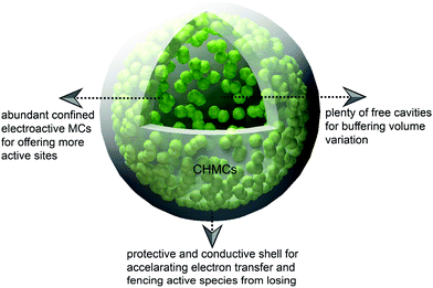 | ||
| Fig. 15 Schematic illustration of the relationship between the structural features of CHMCs and their energy storage performances. | ||
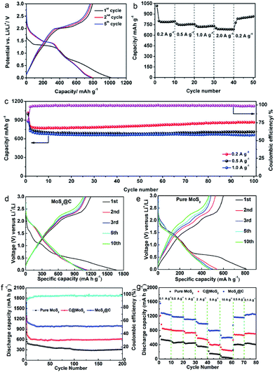 | ||
| Fig. 16 (a) Discharge/charge voltage profiles at 0.2 A g−1, (b) rate performance at current densities ranging from 0.2 to 2.0 A g−1, and (c) cycling performance at 0.2, 0.5, and 1.0 A g−1 and the coulombic efficiency at 0.2 A g−1 for CoSe@carbon nanoboxes. Reproduced from ref. 54, with permission from Wiley, 2016. Charge/discharge voltage profiles of the (d) MoS2@C and (e) pure MoS2 at 1 A g−1. (f) Cycling performance of pure MoS2, C@MoS2, and MoS2@C nanospheres and coulombic efficiency of MoS2@C nanospheres at 1 A g−1. (g) Cycling performance at various current densities (0.1 to 10 A g−1). Reproduced from ref. 41, with permission from American Chemical Society, 2017. | ||
Functionalizing the carbon shell with plenty of pores can further promote the transport of charge/Li+, contributing to preeminent lithium storage performances. For the yolk–shell structured MoS2@C anode with petal-like MoS2 NSs confined within the cavity of hollow mesoporous carbon spheres,41 besides enhancing the electrical conductivity/structural stability of MoS2@C, the CHMCs are also helpful in accelerating the permeation of the electrolyte/reactant inside the HMCSs via their mesoporous shell, thus bringing about sufficient contact between the electrode material and electrolyte/reactant for fast Li+ diffusion and migration. Consequently, a commendable reversible capacity of 993 mA h g−1 at 1 A g−1 after 200 cycles, a rate capability of 595 mA h g−1 at 10 A g−1, and long-term cycle durability (962 mA h g−1 at 1 A g−1 after 1000 cycles and 624 mA h g−1 at 5 A g−1 after 400 cycles) are achieved for LIBs (Fig. 16d–g), outperforming the pure MoS2 and C@MoS2 counterparts. Additionally, Tu and co-workers constructed a hierarchical microsphere assembly (MoS2/C) comprised of interconnected MoS2 NSs and a thin carbon outer layer by means of a template-free strategy.24 The NSs herein are self-assembled to form microspheres, thus producing abundant holes between each other, which can also serve as electrolyte/ion/electron transfer paths for brilliant capacity and rate capability. Besides, the wrapped carbon shell contributes to the enhancement of both the electrical conductivity and structural stability of the whole assembly. By virtue of these structural characteristics, the MoS2/C microspheres display preeminent Li/Na-ion storage bifunctionality (Fig. 17), including superior capacity (Li+: 1017 mA h g−1 at 100 mA g−1 and Na+: 531 mA h g−1 at 100 mA g−1), rate capability (Li+: 434 mA h g−1 at 1 A g−1 and Na+: 102 mA h g−1 at 1 A g−1), and cycling stability (Li+: 902 mA h g−1 after 200 cycles and Na+: 342 mA h g−1 over 100 cycles).
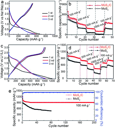 | ||
| Fig. 17 (a) Charge/discharge profiles at 100 mA g−1, and (b) rate performance from 100 mA g−1 to 1000 mA g−1 for MoS2/C electrodes in SIBs. (c) Charge/discharge profiles at 100 mA g−1, (d) rate performance from 100 mA g−1 to 1000 mA g−1, and (e) cycling performance at 100 mA g−1 for MoS2/C electrodes in LIBs. Reproduced from ref. 24, with permission from Wiley, 2018. | ||
Cui's group reported the use of polarized metal sulfides (TiS2) to bind Li2S/Li2Sn species,83 and improved electrochemical behaviour is realized thanks to the strong binding strength between TiS2 and LiPS species (the calculated binding energy between Li2S and single-layer TiS2 is 2.99 eV, which is 10 times higher than that between Li2S and single-layer graphene) and the high conductivity of TiS2. In spite of this, the resultant life span is still unsatisfactory owing to the pronounced volume change under continuous cycling.
Restricting the LiPS species in confined hollow nanostructures (with the property of polarization) which have chemical interactions with the LIPS is an ingenious strategy to prevent the LiPS from losing and shuttling because it can serve as a reservoir for buffering the volume variation of the sulfur cathode during the repeated lithiation and delithiation process.84 So far, the reported materials mainly include modified carbon materials, polymers and some inorganic materials, among which MCs have shown attractive effects.84 For example, Jin and Liu's group prepared an efficient sulfur host material with hollow Co3S4 nanoboxes interconnected by carbon nanotubes (denoted as CNTs/Co3S4-NBs) by a self-templating approach.46 In this composite material, the Co3S4-NBs work well in arresting and storing the LiPS in their cavities via chemical bonding (due to the polar feature of the Co3S4-NBs) and structural confinement effects. Meanwhile, the 3D CNT network enhances the charge transfer properties of the whole framework (the carbon in Li–S batteries is mainly responsible for enhanced electrical conductivity rather than bonding the LIPS due to its nonpolar nature). As a result, this S@CNTs/Co3S4-NB cathode presents superior reversible capacity (a high initial discharge capacity of 1535 mA h g−1 and remains at 1254 mA h g−1 after 100 cycles), rate performance (discharge capacities of 1330, 1165, 988, 859, and 702 mA h g−1 at 0.2, 0.5, 1.0, 2.0, and 5.0C, respectively), and long cycling stability (a capacity decay of 0.042% per cycle at 1.0C and 0.068% per cycle at 2.0C for 500 cycles), exceeding the S@Co3S4-NB and S@CNT counterparts (Fig. 18). Besides, Qiao and Wang's group developed another sulfur host material with nanosized NiS uniformly distributed on carbon hollow spheres (S/NiS@C-HS) using an in situ thermal reduction and post sulfidation method.21 The NiS in S/NiS@C-HS has a high affinity for the polysulfides via chemical interactions while the C-HS can act as both the physical confinement pocket for polysulfide storage and 3D highway for rapid electron transfer. Moreover, the NiS core has strong chemical coupling with the C-HS shell, which favors fast charge transfer and redox kinetics of the sulfur cathode. Consequently, this composite material delivers a capacity decay as low as 0.013% per cycle and a capacity of 695 mA h g−1 at 0.5C after 300 cycles at a high sulfur loading of 2.3 mg cm−2 (Fig. 19).
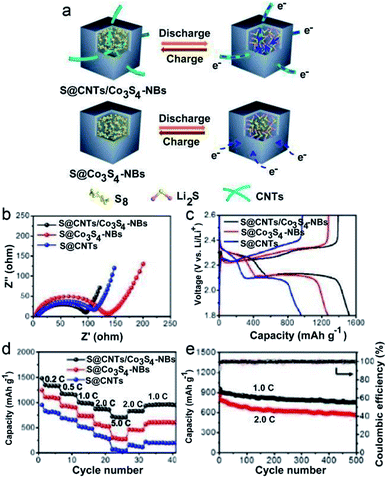 | ||
| Fig. 18 (a) Structural advantages of the S@CNTs/Co3S4-NB cathode over the S@Co3S4-NB cathode during charge–discharge processes. (b) EIS curves, (c) galvanostatic charge–discharge voltage profiles at 0.2C and (d) rate capabilities of the S@CNTs/Co3S4-NB, S@Co3S4-NB and S@CNT electrodes. (e) Long-term cycle performances of the S@CNTs/Co3S4-NB electrode at 1.0 and 2.0C. Reproduced from ref. 46, with permission from American Chemical Society, 2017. | ||
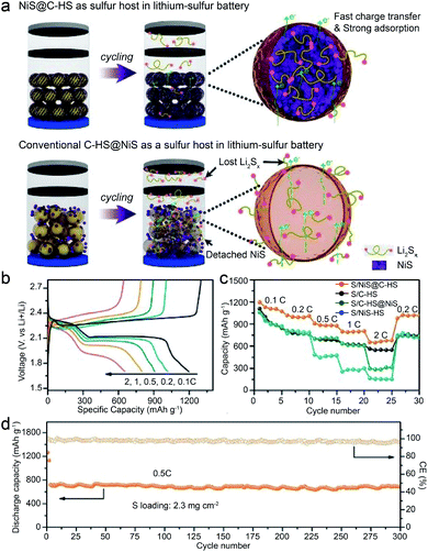 | ||
| Fig. 19 (a) Schematic illustration of NiS@C-HS and C-HS@NiS as sulfur hosts for improving Li–S battery performances. (b) Discharge/charge curves of S/NiS@C-HS at different rates. (c) Rate capabilities of sulfur cathodes at 0.2C. (d) Cycling performances and CE of the S/NiS@C-HS at 0.5C. Reproduced from ref. 21, with permission from Wiley, 2017. | ||
Beyond confinement, the utilization of the soluble characteristic of LIPS is also certified to be an effective method for enhanced Li–S batteries behaviors. This is achieved based on the dynamic precipitation and dissolution equilibrium of LiPS when extra polysulfides are added into the electrolyte.84 For instance, Peng et al. took advantage of high concentration polysulfides as extrinsic healing agents to homogenize the distribution of polysulfides.85 In detail, in the absence of extrinsic polysulfides, the test-generated polysulfides would lead to LiPS with inhomogeneous distribution and thus uneven precipitates. Differently, if high concentration of polysulfide is pre-existed in the electrolyte, the dramatic variation in polysulfides distribution would be mitigated, contributing to relatively homogeneous distributed polysulfides. This would facilitate the mediation of phase transfer, and finally lead to decent Li–S battery properties. Overall, benefiting from the self-healing function of LiPS, Li–S batteries can realize rapid kinetics, higher discharge capacity and stable cycling performance. It is worth mentioning that apart from polysulfides, other additives, such as LiNO3![[thin space (1/6-em)]](https://www.rsc.org/images/entities/char_2009.gif) 86 and P2S5
86 and P2S5![[thin space (1/6-em)]](https://www.rsc.org/images/entities/char_2009.gif) 87 can also offer admirable Li–S battery performance. Considering that the theme of this review is confined hollow structures, details of these additives are not discussed herein.
87 can also offer admirable Li–S battery performance. Considering that the theme of this review is confined hollow structures, details of these additives are not discussed herein.
In attempts to mitigate these problems, the fabrication of CHMCs is of great importance due to their high theoretical specific capacity (such as TiS2), good stability and rich interior space. Hence, more attempts have been made to explore appropriate CHMCs for SIBs. For example, tin disulfide (SnS2) is regarded as a promising anode material for SIBs with high specific capacity, and unfolds great ability for Na+ uptake and release. However, the low conductivity and large volume variation during reaction with Na+ largely hinder its practical application.20,94 To address this issue, our group has recently developed a series of advanced confined hollow structures, including SnS2 NSs confined in hollow carbon nanotubes (SnS2@CNBs), nanoboxes (SnS2@CNBs) and carbon nanospheres (SnS2@CNSs).20 Delightedly, compared with the common SnS2/C nanohybrids, these confined hollow structures all manifest superior sodium storage properties. Especially, SnS2@CNSs exhibit the brightest performances with a specific capacity of about 634 mA h g−1 at 0.2 A g−1 and excellent rate capability of 410 mA h g−1 at 5 A g−1 (Fig. 20). Such superiority mainly originates from their unique structural advantages, i.e., the thin carbon shell can enhance the electrical conductivity of the whole electrode, and protect the active SnS2 component from aggregation, as well as buffering the volume expansion during cycling; besides, the ultrathin SnS2 NSs with high surface area can facilitate Na+ diffusion, leading to capacitance-dominated reactions and high rate performances.
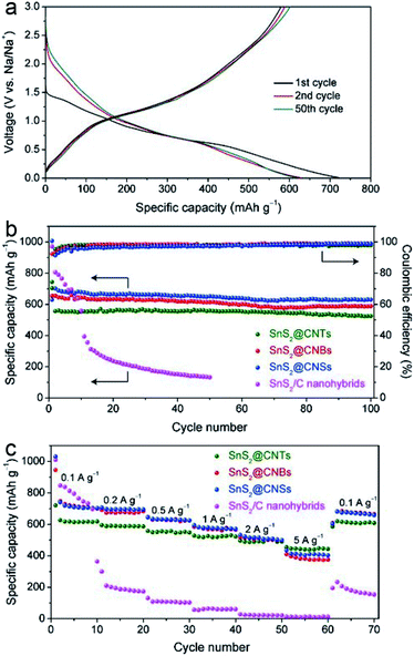 | ||
| Fig. 20 (a) Charge–discharge voltage profiles of SnS2@CNTs at 0.1 A g−1. (b) Cycling performances and corresponding coulombic efficiencies of SnS2@CNTs, SnS2@CNBs, SnS2@CNSs, and SnS2/C nanohybrids at 0.2 A g−1. (c) Rate capabilities of SnS2@CNTs, SnS2@CNBs, SnS2@CNSs, and SnS2/C nanohybrids. Reproduced from ref. 20, with permission from Elsevier, 2018. | ||
Besides SnS2 NSs, other confined nanostructures, such as MoS2/C hierarchical hollow carbon nanospheres56 and SnS@C nanotubes59 also demonstrate glorious electrochemical performance for SIBs. For instance, Sun's group embedded MoSe2 NSs within the cavities of hollow carbon nanospheres to form MoSe2@HCNS construction.43 The MoSe2 herein displays few-layer crystal fringes (≤3) and expanded interlayer spacing (from 0.64 nm to 1.02 nm). Thanks to the expanded (002) crystal planes, 2D few-layer MoSe2 NS structure, and unique carbon shell-stabilized framework, such MoSe2@HCNS exhibits excellent cycling life with discharge capacities of 502 and 471 mA h g−1 over 1000 cycles at 1 and 3 A g−1, respectively. It is noteworthy that the coulombic efficiencies of all the rate performances exceed 98.3%. On further raising the current density to 10 A g−1, the capacity can remain at 382 mA h g−1, and the capacity will recover to 532 mA h g−1 once the current density decreases to 1 A g−1 after 200 cycles. Therefore, the MoSe2@HCNS displays great potential for application in SIBs.
Nanostructured MCs confined in hollow cavities possess a large specific surface area providing abundant reaction sites, vast free space for rapid transport of electrolyte, and importantly, 3D construction for inhibiting the restacking of nanosized MCs, which characteristics make them attractive for pseudocapacitor devices and some progress has been made. For example, Lou et al. developed a double-shelled rhombic dodecahedral cage (RDCs) of zinc–cobalt sulfide (Zn-Co-S) via a sequential chemical etching and sulfurization strategy.34 Benefiting from their unique structural and compositional advantages, this double-shelled Zn-Co-S RDC demonstrates superior hybrid supercapacitor behaviors with a specific capacitance of 1266 F g−1 at 1 A g−1 and long-term cycling stability (91% retention over 10![[thin space (1/6-em)]](https://www.rsc.org/images/entities/char_2009.gif) 000 cycles). By comparison, single-shelled Zn-Co-S RDCs exhibit much lower capacitance. This emphasizes the advantages of double-shelled confinement nanostructures that are capable of containing a higher weight fraction of active species and improving the electric contact. Besides Zn-Co-S RDCs, other double-shelled metal sulfides, such as hierarchical NiS box-in-box hollow structure,33 also exhibit high specific capacitance (668 F g−1 at 1 A g−1), excellent rate capability (71% capacitance retention at 20 A g−1), and good cycling stability (retention of 93.4% after 3000 cycles at 4 A g−1), signifying the superiority of double-shelled confined structures.
000 cycles). By comparison, single-shelled Zn-Co-S RDCs exhibit much lower capacitance. This emphasizes the advantages of double-shelled confinement nanostructures that are capable of containing a higher weight fraction of active species and improving the electric contact. Besides Zn-Co-S RDCs, other double-shelled metal sulfides, such as hierarchical NiS box-in-box hollow structure,33 also exhibit high specific capacitance (668 F g−1 at 1 A g−1), excellent rate capability (71% capacitance retention at 20 A g−1), and good cycling stability (retention of 93.4% after 3000 cycles at 4 A g−1), signifying the superiority of double-shelled confined structures.
Additionally, the carbon-coated confined structure is also efficient for enhanced supercapacitor performances. As an example, by taking advantage of the intrinsic and intended features of the NiS-NC HS comprising the N-doped carbon (NC) hollow shell and NiS core,35 the constructed core–shell structure effectively avoids the agglomeration of the neighboring NiS particles and the NiS dissolution or side reactions, thus showing an excellent specific capacitance of 1170.72 F g−1 (at 0.5 A g−1), Cs value of 260.03 F g−1 (at 0.5 A g−1) and stability (capacitance retention of 90.71% at 6 A g−1 after 4000 cycles) (Fig. 21). Besides, Lu's group developed a novel nanoplate-shaped electrode material with 2D layered MoS2 flakes confined within the hollow interlayer of hexagonal graphitic carbon platelets by a hydrothermal method followed by calcination and etching.77 The obtained sandwich-like assemblies, carbon–MoS2–carbon, show a high specific surface area of 543 m2 g−1 and pore size of about 5.3 nm. The hollow structure ensures plenty of well-defined interior voids which can buffer the volume changes during the charging and discharging process. Moreover, benefiting from their hollow carbon shell, high electronic conductivity is realized. As a result, such particular confined hollow structure exhibits remarkable capacitive behavior with a high specific capacitance of 248 F g−1 (0.12 F cm−2) at 0.1 A g−1 and decent stability over 3000 cycles for symmetric supercapacitor application. These performances are much superior to those of its hollow carbon counterpart, signifying that the superiority of the carbon–MoS2–carbon nanoplate benefits from both the high electronic conductivity of the carbon shell and the intrinsic electrochemical activity of MoS2 stuffing.
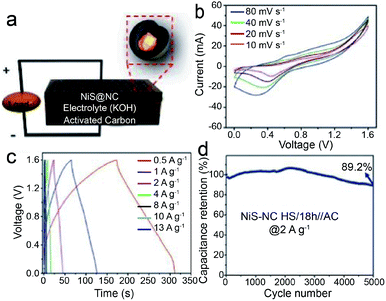 | ||
| Fig. 21 (a) An illustration of the asymmetric NiS-NC HS/18 h//AC supercapacitor, (b) CV curves at different scan rates, (c) GCD curves at different current densities, and (d) cyclic performance of NiS-NC HS/18 h//AC at a current density of 2 A g−1. Reproduced from ref. 35, with permission from Wiley, 2018. | ||
Table 2 summarizes the energy storage performances of different CHMCs, including rate capability, specific capacity, stability and application fields, which can serve as references and guide the fabrication of new-type CHMCs with enhanced energy storage performances.
| Types of materials | Rate capability (mA g−1) | Specific capacity (mA g−1) | Stability | Application field | Reference |
|---|---|---|---|---|---|
| CuS@CoS2 double-shelled nanobox | 304 mA h g−1 at 5 A g−1 | 625 mA h g−1 at 0.1 A g−1 | 79% capacity retention at 0.5 A g−1 after 500 cycles | SIBs | 7 |
| Double-shelled Zn-Co-S rhombic dodecahedral cage | 720 F g−1 at 20 A g−1 | 1266 F g−1 at 1 A g−1 | 91% capacity retention at 10 A g−1 after 10![[thin space (1/6-em)]](https://www.rsc.org/images/entities/char_2009.gif) 000 cycles 000 cycles |
Supercapacitor | 34 |
| CoS NPs/CoS NSs double-shelled hollow structure | 585 F g−1 at 20 A g−1 | 980 F g−1 at 1 A g−1 | 89% capacity retention at 5 A g−1 after 10![[thin space (1/6-em)]](https://www.rsc.org/images/entities/char_2009.gif) 000 cycles 000 cycles |
Supercapacitor | 6 |
| MS (M: Ni, Cu, Mn) box-in-box hollow structure | NiS: 472 F g−1 at 20 A g−1 | NiS: 668 F g−1 at 1 A g−1 | Retention of 93.4% after 3000 cycles at 4 A g−1 | Supercapacitor | 33 |
| “Brain-coral-like” mesoporous CoS2@N-doped carbon nanoshell | 525.3 mA h g−1 at 2C | 1300 mA h g−1 at 0.1C | 903 mA h g−1 at 0.1C after 100 cycles | Li–S battery | 52 |
| Hollow Co9S8 NPs embedded in a carbon nanocage | 278 mA h g−1 at 10C | 536 mA h g−1 at 0.2C and | 365 mA h g−1 at 1C after 150 cycles | Lithium-ion storage | 51 |
| FeS2@C yolk–shell nanobox | 403 mA h g−1 at 5 A g−1 | 560 mA h g−1 at 0.1 A g−1 | 330 mA h g−1 at 2 A g−1 after 800 cycles | SIBs | 36 |
| Metallic and polar Co9S8 inlaid carbon hollow nanopolyhedron | 690 mA h g−1 at 3C | 1160 mA h g−1 at 0.2C | 560 mA h g−1 at 2C after 1000 cycles | Li–S battery | 4 |
| ZnSe@N-doped carbon | 474 mA h g−1 at 12.8 A g−1 | 1162 mA h g−1 at 0.2 A g−1 | 1134 mA h g−1 at 0.6 A g−1 after 500 cycles | LIBs | 53 |
| SnS2 NSs in a hollow carbon nanostructure | SnS2@hollow carbon nanospheres: 517 mA h g−1 at 2 A g−1 | 709 mA h g−1 at 0.1 A g−1 | 631 mA h g−1 at 0.2 A g−1 after 100 cycles | SIBs | 20 |
| MoSe2 NSs confined in a hollow carbon nanosphere | 382 mA h g−1 at 10 A g−1 | 562 mA h g−1 at 1 A g−1 | 501 and 471 mA h g−1 at 1 and 3 A g−1 after 1000 cycles | SIBs | 43 |
| SnS nanosheet @hollow mesoporous carbon sphere-reduced graphene oxide | LIBs: 230 mA h g−1 at 3.2 A g−1; SIBs: 336 mA h g−1 at 1.6 A g−1 | LIBs: 1362 mA h g−1 at 0.2 A g−1; SIBs: 825 mA h g−1 at 0.2 A g−1 | LIBs: 1027 mA h g−1 at 0.2 A g−1 after 100 cycles. SIBs: 445 mA h g−1 at 0.1 A g−1 after 100 cycles | LIBs and SIBs | 47 |
| FeS2 NSs encapsulated in a 3D porous carbon sphere | 453.6 mA h g−1 at 2 A g−1 | 514.9 mA h g−1 at 0.5 A g−1 | 272.4 mA h g−1 at 5 A g−1 after 500 cycles | SIBs | 37 |
| Petal-like MoS2 NSs confined in a mesoporous carbon sphere | 595 mA h g−1 at 10 A g−1 | 1280 mA h g−1 at 0.1 A g−1 | 962 mA h g−1 at 1 A g−1 after 1000 cycles | LIBs | 41 |
| Bullet-like Cu9S5@nitrogen-doped carbon hollow structure | 237 mA h g−1 at 5 A g−1 | 385 mA h g−1 at 0.3 A g−1 | 79% capacity retention at 2 A g−1 after 4000 cycles | SIBs | 22 |
| CoSe@carbon nanobox | 686 mA h g−1 at 2.0 A g−1 | 787 mA h g−1 at 0.2 A g−1 | 94.5% (711 mA h g−1) of the 2nd cycle discharge capacity retention at 0.5 A g−1 in the 100th cycle | LIBs | 54 |
| NiS core–nitrogen-doped carbon hollow shell structure | 843.75 F g−1 at 10 A g−1 | 1170.72 F g−1 at 0.5 A g−1 | 90.71% capacitance retention at 6 A g−1 after 4000 cycles | Supercapacitor | 35 |
| Coconut-like monocrystalline SnS/C nanosphere | 557 mA h g−1 at 5 A g−1 | 936 mA h g−1 at 0.1 A g−1 | 936 mA h g−1 at 0.1 A g−1 for 50 cycles and 830 mA h g−1 at 0.5 A g−1 for another 250 cycles | LIBs | 55 |
| Coupled carbon NSs/MoS2 nanocrystal hierarchical hollow nanosphere | 262.7 mA h g−1 at 8 A g−1 | 574.7 mA h g−1 at 0.2 A g−1 | 410 mA h g−1 at 4 A g−1 after 1000 cycles | SIBs | 56 |
| Pistachio-shuck-like MoSe2/C core/shell nanostructure | 224 mA h g−1 at 2.0 A g−1 | 382 mA h g−1 at 0.2 A g−1 | 226 mA h g−1 at 1 A g−1 over 1000 cycles | Potassium-ion battery | 3 |
| WS2 NSs vertically embedded in hollow mesoporous carbon | 396 mA h g−1 at 10 A g−1 | 935 mA h g−1 at 0.1 A g−1 | 784 mA h g−1 at 1 A g−1 after 1000 cycles | LIBs | 42 |
| Hierarchical Co9S8@carbon hollow microsphere | 411 mA h g−1 at 5 A g−1 | 614 mA h g−1 at 0.1 A g−1 | 223 mA h g−1 at 5 A g−1 after 10![[thin space (1/6-em)]](https://www.rsc.org/images/entities/char_2009.gif) 000 cycles 000 cycles |
SIBs | 44 |
| 3D hybrid of NiS and hollow carbon spheres | 674 mA h g−1 at 2C | 1196 mA h g−1 at 0.1C | 695 mA h g−1 at 0.5C after 300 cycles | Li–S battery | 21 |
| Carbon-coated 3D porous interconnected SnS | Lithium storage: 329 mA h g−1 at 10 A g−1; SIBs: 145 mA h g−1 at 10 A g−1 | Lithium storage: 953 mA h g−1 at 0.1 A g−1; SIBs: 419 mA h g−1 at 0.1 A g−1 | 80% capacity retention after 300 cycles (lithium storage: 535 mA h g−1 at 1 A g−1; SIBs: 266 mA h g−1 at 1 A g−1) | LIBs and SIBs | 57 |
| Hierarchical nanotubes constructed by SnS NSs@C | 290 mA h g−1 at 5 A g−1 | 440 mA h g−1 at 0.2 A g−1 | 440 mA h g−1 at 0.2 A g−1 after 100 cycles | SIBs | 59 |
| MoSe2 confined within a ZnSe–C hollow porous sphere | Lithium storage: 363 mA h g−1 at 2 A g−1; SIBs: 328 mA h g−1 at 4 A g−1 | Lithium storage: 1051 mA h g−1 at 0.2 A g−1; SIBs: 468 mA h g−1 at 0.2 A g−1 | Lithium storage: 524 mA h g−1 at 4 A g−1 after 600 cycles; SIBs: 381 mA h g−1 at 4 A g−1 after 250 cycles | LIBs and SIBs | 18 |
| NiCo2(SxSe1−x)5/graphitic carbon | Pseudocapacitors: 440.1C g−1 at 20 A g−1. LIBs: 348.7 mA h g−1 at 5 A g−1 | Pseudocapacitors: 560.7C g−1 at 1 A g−1; LIBs: 906.1 mA h g−1 at 0.1 A g−1 | Pseudocapacitor 476.2C g−1 (93.7% capacity retention) at 6 A g−1 after 2000 cycles LIBs: 865.2 mA h g−1 at 0.2 A g−1 after 100 cycles | Pseudocapacitors and LIBs | 60 |
| NiCo-LDH/ Co9S8 (LDH: layered double hydroxide) | 1025C g−1 at 20 A g−1 | 1653C g−1 at 4 A g−1 | 95.4% capacity retention after 3000 cycles | Pseudocapacitors | 61 |
| SnS2 NSs coating on nanohollow CoS2/C | About 400.1 mA h g−1 at 10 A g−1 | 854.5 mA h g−1 at 0.1 A g−1 | 400.1 mA h g−1 at 10 A g−1 after 3500 cycles | SIBs | 11 |
| Hexagonal carbon–MoS2–carbon nanoplates with a hollow sandwich structure | 178 F g−1 at 1 A g−1 | 248 F g−1 at 0.1 A g−1 | 85% capacity retention at 1 A g−1 after 3000 cycles | Supercapacitor | 62 |
| Sandwich-like hierarchical TiO2@carbon@MoS2 tubular nanostructure | 612 mA h g−1 at 2 A g−1 | 925 mA h g−1 at 0.1 A g−1 | 590 mA h g−1 at 1 A g−1 after 200 cycles | LIBs | 63 |
| Na2Se confined within a single-walled carbon nanotube | Theoretical investigation | Sodium–selenium battery | 64 | ||
| Bamboo-like hollow tubes with a MoS2/N-doped-C interface | 131 mA h g−1 at 2 A g−1 | 330 mA h g−1 at 0.05 A g−1 | 151 mA h g−1 at 0.5 A g−1 after 1000 cycles | Potassium-ion battery | 65 |
| Fe1−xS encapsulated in a carbon nanotube | 326.3 mA h g−1 at 8 A g−1 | 492.7 mA h g−1 at 0.2 A g−1 | 449.2 mA h g−1 at 0.5 A g−1 after 200 cycles | SIBs | 40 |
| Carbon nanotubes filled with Fe–S NPs | 348 mA h g−1 at 2 A g−1 | 698 mA h g−1 at 0.05 A h−1 | 670 mA h g−1 at 0.05 A g−1 after 65 cycles | LIBs | 19 |
| FeS2 NPs encapsulated in a carbon nanotube | 345 mA h g−1 at 5 A g−1 | 800 mA h g−1 at 0.2 A g−1 | 525 mA h g−1 at 2 A g−1 after 1000 cycles | LIBs | 66 |
| Peapod-like carbon-encapsulated CoS or CoSe nanowire | CoS: 235 mA h g−1 at 5 A g−1 CoSe: 241 mA h g−1 at 5 A g−1 | CoS: 379 mA h g−1 at 0.1 A g−1 CoSe: 350 mA h g−1 at 0.1 A g−1 | CoS: 294 mA h g−1 at 0.1 A g−1 after 100 cycles CoSe: 299 mA h g−1 at 0.1 A g−1 after 100 cycles | SIBs | 38 |
| MoS2@C nanotube | LIBs: 850 mA h g−1 at 5C; SIBs: 370 mA h g−1 at 5C | LIBs: 1326.9 mA h g−1 at 0.1C; SIBs: 610 mA h g−1 at 0.1C | LIBs: 1058.4 mA h g−1 (90% capacity retention) at 0.5C after 300 cycles. SIBs: 480 mA h g−1 at 0.5C after 200 cycles. | LIBs and SIBs | 23 |
| Interlaced carbon nanotube threaded hollow Co3S4 nanobox | 702 mA h g−1 at 5C | 1254 mA h g−1 at 0.2C | 752 mA h g−1 at 1C after 500 cycles | Li–S battery | 46 |
| CNT/CoS@C | 276 mA h g−1 at 5 A g−1 | 562 mA h g−1 at 0.1 A g−1 | 398 mA h g−1 at 0.5 mA g−1 after 200 cycles | SIBs | 67 |
| Hollow SnO2/SnS2 hybrid | 245.4 mA h g−1 at 2.5 A g−1 | 497.8 mA h g−1 at 0.3 A g−1 | 485.6 mA h g−1 at 0.3 A g−1 after 100 cycles | SIBs | 68 |
| ZnS nanorods rooted in the porous carbon polyhedron | 608 mA h g−1 at 1.6 A g−1 | 1388 mA h g−1 at 0.1 A g−1 | 840 mA h g−1 at 0.6 A g−1 after 300 cycles | LIBs | 69 |
| Hollow nanospheres assembled from NiCo2S4@C NSs | 700 mA h g−1 at 3.2 A g−1 | 1592 mA h g−1 at 0.5 A g−1 | 1178 mA h g−1 at 0.5 A g−1 after 200 cycles | LIBs | 49 |
| (Co9S8 quantum dots@hollow carbon polyhedral)@rGO | 330 mA h g−1 at 6.4 A g−1 | 738 mA h g−1 at 0.2 A g−1 | 628 mA h g−1 at 0.3 A g−1 after 500 cycles | SIBs | 48 |
| Sulfur-grafted hollow carbon sphere | 110 mA h g−1 at 5 A g−1 | 581 mA h g−1 at 0.025 A g−1 | 93% capacity retention from the 5th to 1000th cycles at 3 A g−1 | Potassium-ion batteries | 70 |
| Nitrogen-doped double-shelled hollow carbon spheres-sulfur hybrid | 600 mA h g−1 at 2C | 1360 mA h g−1 at 0.2C | 940 mA h g−1 at 0.2C after 100 cycles | Li–S battery | 17 |
| CoS embedded within porous carbon polyhedral/carbon nanotubes | 752 mA h g−1 at 10 A g−1 | 1668 mA h g−1 at 0.2 A g−1 | 1668 mA h g−1 at 0.2 A g−1 after 100 cycles | LIBs | 71 |
| FeS nanodots⊂porous graphitic carbon nanowires | 322 mA h g−1 at 10C | 579 mA h g−1 at 0.1C | 400 mA h g−1 at 0.5C after 50 cycles | LIBs | 73 |
| NiCo2S4 encapsulated in a hollow nitrogen-doped carbon cube | 353 mA h g−1 at 1 A g−1 | 480 mA h g−1 at 0.1 A g−1 | 427 mA h g−1 at 0.5 A g−1 after 500 cycles | LIBs | 74 |
Conclusions
In summary, we have reviewed the recent progress in the synthetic strategies of diverse CHMCs as well as their growth mechanisms. These CHMCs can be mainly classified into six categories, including double-shelled confined hollow structures with different shapes, core–shell confined structure with a hollow cavity, hierarchical NPs/NS-based confined structures encapsulated within different-shaped single-shelled hollow shells, and CHMCs with composite structures/components. Thanks to their unique structure features, including plenty of free cavities for buffering large volume variation, abundant electroactive MCs for offering more active sites and a protective carbon/MC shell for preventing active species from losing,97 these CHMCs demonstrate admirable energy storage performances as electrode materials for LIBs, SIBs, Li–S batteries and supercapacitor systems. Although these studies provide massive advanced electrode materials which deepen our understanding of the link between confined hollow structure engineering and improved energy storage performance, there is still plenty of room for the further study of this research area. First, from the perspective of synthesis, precise control and fabrication of CHMCs through facile and large-scale synthesis methods are quite difficult. Further expanding the existing methods and developing new templates and strategies for complex confined structures would be very useful. Especially, the hollow structures will inevitably reduce the volumetric energy density of the electrodes because of the presence of interior cavities, so fine tuning the shell thickness and void size of the confined hollow structures is highly desirable in order to get a balance between high volumetric energy density and suitable void space for accommodating mechanical stress. Due to the difference in various energy storage systems, there are several issues, such as single-shell and multi-shell, shell composition, that need to be addressed toward rational design of confined hollow structures. Second, in situ electrochemistry studies combined with TEM, XPS and etc. need to be developed. The structural and chemical environment changes are usually accompanied by morphological and valence state changes that impact the electrochemical performances of materials. Therefore, various in situ techniques are of great potential in studying the microstructure transformation and ion diffusion at various length scales and high temporal resolution, offering important insights for designing structural and compositional modification strategies for improving system performance. Additionally, although theoretical calculation has been widely applied in electrochemical catalytic systems, there have been few reports on energy storage systems so far. The combination of experimental and theoretical calculation is expected to bring more possibilities in modulating the properties of CHMCs.Conflicts of interest
There are no conflicts to declare.Acknowledgements
This work was financially supported by the National Natural Science Foundation of China (21533012 and 21625502). The authors appreciate the financial support from the PAPD of Jiangsu Higher Education Institutions.Notes and references
- Y. Zhang, Q. Zhou, J. Zhu, Q. Yan, S. X. Dou and W. Sun, Adv. Funct. Mater., 2017, 27, 1702317 CrossRef.
- X.-Y. Yu, L. Yu and X. W. D. Lou, Adv. Energy Mater., 2016, 6, 1501333 CrossRef.
- W. Wang, B. Jiang, C. Qian, F. Lv, J. Feng, J. Zhou, K. Wang, C. Yang, Y. Yang and S. Guo, Adv. Mater., 2018, 30, 1801812 CrossRef.
- T. Chen, L. Ma, B. Cheng, R. Chen, Y. Hu, G. Zhu, Y. Wang, J. Liang, Z. Tie, J. Liu and Z. Jin, Nano Energy, 2017, 38, 239–248 CrossRef CAS.
- L. Yu, J. F. Yang and X. W. Lou, Angew. Chem., Int. Ed., 2016, 55, 13422–13426 CrossRef CAS PubMed.
- H. Hu, Bu Y. Guan and X. W. Lou, Chem, 2016, 1, 102–113 CAS.
- Y. Fang, B. Y. Guan, D. Luan and X. W. D. Lou, Angew. Chem., Int. Ed. Engl., 2019, 58, 7739–7743 CrossRef CAS.
- Z. Wei, L. Wang, M. Zhuo, W. Ni, H. Wang and J. Ma, J. Mater. Chem. A, 2018, 6, 12185–12214 RSC.
- H. Li, Y. Su, W. Sun and Y. Wang, Adv. Funct. Mater., 2016, 26, 8345–8353 CrossRef CAS.
- N.-S. Choi, Z. Chen, S. A. Freunberger, X. Ji, Y.-K. Sun, K. Amine, G. Yushin, L. F. Nazar, J. Cho and P. G. Bruce, Angew. Chem., Int. Ed., 2012, 51, 9994–10024 CrossRef CAS PubMed.
- L. Shi, D. Li, P. Yao, J. Yu, C. Li, B. Yang, C. Zhu and J. Xu, Small, 2018, 14, 1802716 CrossRef PubMed.
- J. Wang, D. Chao, J. Liu, L. Li, L. Lai, J. Lin and Z. Shen, Nano Energy, 2014, 7, 151–160 CrossRef CAS.
- Y. Fang, X. Y. Yu and X. W. D. Lou, Adv. Mater., 2018, 30, e1706668 CrossRef PubMed.
- X. Zhou, X. Zhu, X. Liu, Y. Xu, Y. Liu, Z. Dai and J. Bao, J. Phys. Chem. C, 2014, 118, 22426–22431 CrossRef CAS.
- J. Wang, Y. Cui and D. Wang, Adv. Mater., 2019, 31, e1801993 CrossRef PubMed.
- F. Xie, L. Zhang, C. Ye, M. Jaroniec and S. Z. Qiao, Adv. Mater., 2019, 31, e1800492 CrossRef.
- G. Zhou, Y. Zhao and A. Manthiram, Adv. Energy Mater., 2015, 5, 1402263 CrossRef.
- L. Zeng, Y. Fang, L. Xu, C. Zheng, M.-Q. Yang, J. He, H. Xue, Q. Qian, M. Wei and Q. Chen, Nanoscale, 2019, 11, 6766–6775 RSC.
- W. J. Yu, C. Liu, L. Zhang, P. X. Hou, F. Li, B. Zhang and H. M. Cheng, Adv. Sci., 2016, 3, 1600113 CrossRef PubMed.
- Y. Liu, X.-Y. Yu, Y. Fang, X. Zhu, J. Bao, X. Zhou and X. W. Lou, Joule, 2018, 2, 725–735 CrossRef CAS.
- C. Ye, L. Zhang, C. Guo, D. Li, A. Vasileff, H. Wang and S.-Z. Qiao, Adv. Funct. Mater., 2017, 27, 1702524 CrossRef.
- Y. Fang, X. Y. Yu and X. W. D. Lou, Angew. Chem., Int. Ed., 2019, 58, 7744–7748 CrossRef CAS PubMed.
- X. Zhang, X. Li, J. Liang, Y. Zhu and Y. Qian, Small, 2016, 12, 2484–2491 CrossRef CAS PubMed.
- W. Tang, X. Wang, Y. Zhong, D. Xie, X. Zhang, X. Xia, J. Wu, C. Gu and J. Tu, Chem.–Eur. J., 2018, 24, 11220–11226 CrossRef CAS.
- L. Shi and T. Zhao, J. Mater. Chem. A, 2017, 5, 3735–3758 RSC.
- X. Wang, J. Feng, Y. Bai, Q. Zhang and Y. Yin, Chem. Rev., 2016, 116, 10983–11060 CrossRef CAS PubMed.
- X. Cao, C. Tan, X. Zhang, W. Zhao and H. Zhang, Adv. Mater., 2016, 28, 6167–6196 CrossRef CAS PubMed.
- S. M. Oh, S. B. Patil, X. Jin and S. J. Hwang, Chem.–Eur. J., 2018, 24, 4757–4773 CrossRef CAS PubMed.
- Q. Yun, L. Li, Z. Hu, Q. Lu, B. Chen and H. Zhang, Adv. Mater., 2019, 1903826 Search PubMed.
- J. Wang, J. Wan and D. Wang, Acc. Chem. Res., 2019, 52, 2169–2178 CrossRef CAS PubMed.
- X. Zhao, J. Wang, R. Yu and D. Wang, J. Am. Chem. Soc., 2018, 140, 17114–17119 CrossRef CAS PubMed.
- H. Yang, S. Huang, X. Huang, F. Fan, W. Liang, X. H. Liu, L. Q. Chen, J. Y. Huang, J. Li, T. Zhu and S. Zhang, Nano Lett., 2012, 12, 1953–1958 CrossRef CAS PubMed.
- X.-Y. Yu, L. Yu, L. Shen, X. Song, H. Chen and X. W. D. Lou, Adv. Funct. Mater., 2014, 24, 7440–7446 CrossRef CAS.
- P. Zhang, B. Y. Guan, L. Yu and X. W. D. Lou, Angew. Chem., Int. Ed., 2017, 56, 7141–7145 CrossRef CAS PubMed.
- S. N. Tiruneh, B. K. Kang, H. W. Choi, S. B. Kwon, M. S. Kim and D. H. Yoon, Small, 2018, 14, e1802933 CrossRef PubMed.
- Z. Liu, T. Lu, T. Song, X.-Y. Yu, X. W. Lou and U. Paik, Energy Environ. Sci., 2017, 10, 1576–1580 RSC.
- F. Wang, G. Li, X. Meng, Y. Li, Q. Gao, Y. Xu and W. Cui, Inorg. Chem. Front., 2018, 5, 2462–2471 RSC.
- C. Wu, Y. Jiang, P. Kopold, P. A. van Aken, J. Maier and Y. Yu, Adv. Mater., 2016, 28, 7276–7283 CrossRef CAS PubMed.
- W.-J. Yu, C. Liu, L. Zhang, P.-X. Hou, F. Li, B. Zhang and H.-M. Cheng, Adv. Sci., 2016, 3, 1600113 CrossRef PubMed.
- Y. Xiao, J.-Y. Hwang, I. Belharouak and Y.-K. Sun, ACS Energy Lett., 2017, 2, 364–372 CrossRef CAS.
- X. Zhang, R. Zhao, Q. Wu, W. Li, C. Shen, L. Ni, H. Yan, G. Diao and M. Chen, ACS Nano, 2017, 11, 8429–8436 CrossRef CAS PubMed.
- X. Zhang, R. Zhao, Q. Wu, W. Li, C. Shen, L. Ni, H. Yan, G. Diao and M. Chen, J. Mater. Chem. A, 2018, 6, 19004–19012 RSC.
- H. Liu, H. Guo, B. Liu, M. Liang, Z. Lv, K. R. Adair and X. Sun, Adv. Funct. Mater., 2018, 28, 1707480 CrossRef.
- M. Yin, X. Feng, D. Zhao, Y. Zhao, H. Li, W. Zhou, H. Liu, X. Bai, H. Wang, C. Feng and Q. Jiao, ACS Sustainable Chem. Eng., 2019, 7, 6122–6130 CrossRef CAS.
- W. Zhu, Z. Chen, Y. Pan, R. Dai, Y. Wu, Z. Zhuang, D. Wang, Q. Peng, C. Chen and Y. Li, Adv. Mater., 2019, 31, e1800426 CrossRef PubMed.
- T. Chen, Z. Zhang, B. Cheng, R. Chen, Y. Hu, L. Ma, G. Zhu, J. Liu and Z. Jin, J. Am. Chem. Soc., 2017, 139, 12710–12715 CrossRef CAS PubMed.
- S. Zhang, G. Wang, Z. Zhang, B. Wang, J. Bai and H. Wang, Small, 2019, 15, e1900565 CrossRef PubMed.
- Z. Chen, R. Wu, M. Liu, H. Wang, H. Xu, Y. Guo, Y. Song, F. Fang, X. Yu and D. Sun, Adv. Funct. Mater., 2017, 27, 1702046 CrossRef.
- X. Wu, S. Li, B. Wang, J. Liu and M. Yu, Phys. Chem. Chem. Phys., 2017, 19, 11554–11562 RSC.
- B. Jia, Q. Yu, Y. Zhao, M. Qin, W. Wang, Z. Liu, C.-Y. Lao, Y. Liu, H. Wu, Z. Zhang and X. Qu, Adv. Funct. Mater., 2018, 28, 1803409 CrossRef.
- J. Liu, C. Wu, D. Xiao, P. Kopold, L. Gu, P. A. van Aken, J. Maier and Y. Yu, Small, 2016, 12, 2354–2364 CrossRef CAS PubMed.
- S. D. Seo, D. Park, S. Park and D. W. Kim, Adv. Funct. Mater., 2019, 29, 1903712 CrossRef.
- Z. Chen, R. Wu, H. Wang, K. H. L. Zhang, Y. Song, F. Wu, F. Fang and D. Sun, Nano Res., 2017, 11, 966–978 CrossRef.
- H. Hu, J. Zhang, B. Guan and X. W. Lou, Angew. Chem., Int. Ed., 2016, 55, 9514–9518 CrossRef CAS PubMed.
- Z. Deng, H. Jiang, Y. Hu, C. Li, Y. Liu and H. Liu, AIChE J., 2018, 64, 1965–1974 CrossRef CAS.
- Y. Yang, M. Luo, Y. Xing, S. Wang, W. Zhang, F. Lv, Y. Li, Y. Zhang, W. Wang and S. Guo, Adv. Mater., 2018, 30, e1706085 CrossRef PubMed.
- C. Zhu, P. Kopold, W. Li, P. A. van Aken, J. Maier and Y. Yu, Adv. Sci., 2015, 2, 1500200 CrossRef PubMed.
- Y. Guo, J. Tang, H. Qian, Z. Wang and Y. Yamauchi, Chem. Mater., 2017, 29, 5566–5573 CrossRef CAS.
- P. He, Y. Fang, X. Y. Yu and X. W. D. Lou, Angew. Chem., Int. Ed., 2017, 56, 12202–12205 CrossRef CAS PubMed.
- M. Yi, A. Wu, Q. Chen, D. Cai and H. Zhan, Chem. Eng. J., 2018, 351, 678–687 CrossRef CAS.
- G. Yilmaz, K. M. Yam, C. Zhang, H. J. Fan and G. W. Ho, Adv. Mater., 2017, 29, 1606814 CrossRef PubMed.
- T. Quan, N. Goubard-Bretesché, E. Härk, Z. Kochovski, S. Mei, N. Pinna, M. Ballauff and Y. Lu, Chem.–Eur. J., 2019, 25, 4757–4766 CrossRef CAS PubMed.
- S. Wang, B. Y. Guan, L. Yu and X. W. D. Lou, Adv. Mater., 2017, 29, 1702724 CrossRef PubMed.
- L. Wang, X. Zhang, L. Deng, J. Tang, H. Deng, W. Hu and Z. Liu, ACS Appl. Mater. Interfaces, 2019, 11, 4995–5002 CrossRef CAS PubMed.
- Q. Y. B. Jia, Y. Zhao, M. Qin, W. Wang, Z. Liu, C.-Y. Lao, Y. Liu, H. Wu, Z. Zhang and X. Qu, Adv. Funct. Mater., 2018, 1803409 CrossRef.
- L. Xu, Y. Hu, H. Zhang, H. Jiang and C. Li, ACS Sustainable Chem. Eng., 2016, 4, 4251–4255 CrossRef CAS.
- F. Han, C. Y. Jun Tan and Z. Gao, J. Power Sources, 2017, 339, 41–50 CrossRef CAS.
- K. Wang, Y. Huang, X. Qin, M. Wang, X. Sun and M. Yu, ChemElectroChem, 2017, 4, 2308–2313 CrossRef CAS.
- Z. Chen, R. Wu, H. Wang, Y. Jiang, L. Jin, Y. Guo, Y. Song, F. Fang and D. Sun, Chem. Eng. J., 2017, 326, 680–690 CrossRef CAS.
- J. Ding, H. Zhang, H. Zhou, J. Feng, X. Zheng, C. Zhong, E. Paek, W. Hu and D. Mitlin, Adv. Mater., 2019, 31, e1900429 CrossRef PubMed.
- R. Wu, D. P. Wang, X. Rui, B. Liu, K. Zhou, A. W. Law, Q. Yan, J. Wei and Z. Chen, Adv. Mater., 2015, 27, 3038–3044 CrossRef CAS PubMed.
- L. Yu, B. Y. Xia, X. Wang and X. W. Lou, Adv. Mater., 2016, 28, 92–97 CrossRef CAS PubMed.
- C. Zhu, Y. Wen, P. A. van Aken, J. Maier and Y. Yu, Adv. Funct. Mater., 2015, 25, 2335–2342 CrossRef CAS.
- D. Yuan, G. Huang, D. Yin, X. Wang, C. Wang and L. Wang, ACS Appl. Mater. Interfaces, 2017, 9, 18178–18186 CrossRef CAS PubMed.
- Z. Zhang, Y.-P. Deng, Z. Xing, D. Luo, S. Sy, Z. P. Cano, G. Liu, Y. Jiang and Z. Chen, ACS Nano, 2019, 13, 7062–7072 CrossRef CAS PubMed.
- Q. Yun, Q. Lu, X. Zhang, C. Tan and H. Zhang, Angew. Chem., Int. Ed., 2018, 57, 626–646 CrossRef CAS PubMed.
- F. Tu, X. Xu, P. Wang, L. Si, X. Zhou and J. Bao, J. Phys. Chem. C, 2017, 121, 3261–3269 CrossRef CAS.
- C. Xu, D. Niu, N. Zheng, H. Yu, J. He and Y. Li, ACS Sustainable Chem. Eng., 2018, 6, 5999–6007 CrossRef CAS.
- Q. Cui, Y. Zhong, L. Pan, H. Zhang, Y. Yang, D. Liu, F. Teng, Y. Bando, J. Yao and X. Wang, Adv. Sci., 2018, 5, 1700902 CrossRef PubMed.
- G. Chen, L. Yan, H. Luo and S. Guo, Adv. Mater., 2016, 28, 7580–7602 CrossRef CAS PubMed.
- Y. Xu, Y. Wen, Y. Zhu, K. Gaskell, K. A. Cychosz, B. Eichhorn, K. Xu and C. Wang, Adv. Funct. Mater., 2015, 25, 4312–4320 CrossRef CAS.
- A. Fu, C. Wang, F. Pei, J. Cui, X. Fang and N. Zheng, Small, 2019, 15, 1804786 CrossRef PubMed.
- Z. W. Seh, J. H. Yu, W. Li, P.-C. Hsu, H. Wang, Y. Sun, H. Yao, Q. Zhang and Y. Cui, Nat. Commun., 2014, 5, 5017 CrossRef CAS PubMed.
- T. Tang and Y. Hou, Small Methods, 2019, 1900001 CrossRef.
- H. J. Peng, J. Q. Huang, X. Y. Liu, X. B. Cheng, W. T. Xu, C. Z. Zhao, F. Wei and Q. Zhang, J. Am. Chem. Soc., 2017, 139, 8458–8466 CrossRef CAS PubMed.
- W. Li, H. Yao, K. Yan, G. Zheng, Z. Liang, Y. M. Chiang and Y. Cui, Nat. Commun., 2015, 6, 7436 CrossRef CAS PubMed.
- J. Liang, X. Li, Y. Zhao, L. V. Goncharova, G. Wang, K. R. Adair, C. Wang, R. Li, Y. Zhu, Y. Qian, L. Zhang, R. Yang, S. Lu and X. Sun, Adv. Mater., 2018, 30, e1804684 CrossRef.
- Y. Fang, X.-Y. Yu and X. W. Lou, Matter, 2019, 1, 90–114 CrossRef.
- S. Wang, Y. Fang, X. Wang and X. W. Lou, Angew. Chem., 2019, 131, 770–773 CrossRef.
- Z. Hu, Q. Liu, S. L. Chou and S. X. Dou, Adv. Mater., 2017, 29, 1700606 CrossRef PubMed.
- F. Li, Z. Wei, A. Manthiram, Y. Feng, J. Ma and L. Mai, J. Mater. Chem. A, 2019, 7, 9406–9431 RSC.
- L. Hu, X. Zhu, Y. Du, Y. Li, X. Zhou and J. Bao, Chem. Mater., 2015, 27, 8138–8145 CrossRef CAS.
- Y. Du, X. Zhu, X. Zhou, L. Hu, Z. Dai and J. Bao, J. Mater. Chem. A, 2015, 3, 6787–6791 RSC.
- Y. Du, X. Zhu, L. Si, Y. Li, X. Zhou and J. Bao, J. Phys. Chem. C, 2015, 119, 15874–15881 CrossRef CAS.
- L. Hou, H. Hua, R. Bao, Z. Chen, C. Yang, S. Zhu, G. Pang, L. Tong, C. Yuan and X. Zhang, ChemPlusChem, 2016, 81, 557–563 CrossRef CAS.
- L. Hou, Y. Shi, C. Wu, Y. Zhang, Y. Ma, X. Sun, J. Sun, X. Zhang and C. Yuan, Adv. Funct. Mater., 2018, 28, 1705921 CrossRef.
- Y. Wu, S. Hu, R. Xu, J. Wang, Z. Peng, Q. Zhang and Y. Yu, Nano Lett., 2019, 19, 1351–1358 CrossRef PubMed.
| This journal is © The Royal Society of Chemistry 2020 |


