 Open Access Article
Voltage-controlled skyrmion-based nanodevices for neuromorphic computing using a synthetic antiferromagnet†
Ziyang
Yu
a,
Maokang
Shen‡
b,
Zhongming
Zeng
 c,
Shiheng
Liang
d,
Yong
Liu
a,
Ming
Chen
a,
Zhenhua
Zhang
a,
Zhihong
Lu
 e,
Long
You
 b,
Xiaofei
Yang
b,
Yue
Zhang
b,
Xiaofei
Yang
b,
Yue
Zhang
 *b and
Rui
Xiong
*a
aKey Laboratory of Artificial Micro- and Nano-structures of Ministry of Education, School of Physics and Technology, Wuhan University, Wuhan, 430072, P. R. China. E-mail: xiongrui@whu.edu.cn
bSchool of Optical and Electronic Information, Huazhong University of Science and Technology, Wuhan, 430074, P. R. China. E-mail: yue-zhang@hust.edu.cn
cKey Laboratory of Multifunctional Nanomaterials and Smart Systems, Suzhou Institute of Nano-Tech and Nano-Bionics, Chinese Academy of Sciences, Suzhou, Jiangsu 215123, P. R. China
dDepartment of Physics, Hubei University, Wuhan 430062, P. R. China
eThe State Key Laboratory of Refractories and Metallurgy, School of Materials and Metallurgy, Wuhan University of Science and Technology, Wuhan, 430081, P. R. China
First published on 7th February 2020
Abstract
Spintronics exhibits significant potential for a neuromorphic computing system with high speed, high integration density, and low dissipation. In this article, we propose an ultralow-dissipation skyrmion-based nanodevice composed of a synthetic antiferromagnet (SAF) and a piezoelectric substrate for neuromorphic computing. Skyrmions/skyrmion bubbles can be generated in the upper layer of an SAF with a weak anisotropy energy (Ea). Applying a weak electric field on the heterostructure, interlayer antiferromagnetic coupling can be manipulated, giving rise to a continuous transition between a large skyrmion bubble and a small skyrmion. This thus induces a variation of the resistance of a magnetic tunneling junction that can mimic the potentiation/depression of a synapse and the leaky-integral-and-fire function of a neuron at a cost of a very low energy consumption of 0.3 fJ. These results pave a way to ultralow power neuromorphic computing applications.
Artificial neural networks (ANNs), which are based on a complicated connection of artificial neurons and synapses mimicking the neural network in the brain, have attracted extensive interest due to their powerful intelligence for information processing. However, the energy consumption of an ANN system developed on a traditional microelectronic element, such as a complementary metal oxide semiconductor, is much larger than that of the brain. Therefore, several functional devices are candidates for the implementation of an ANN, such as memristors,1 phase change memory,2,3 ferroelectric tunneling junctions,4 and spintronic devices.5–7 Among them, spintronic devices with the advantages of a high speed, a high integration degree, and low energy consumption have been unveiled to have great potential for developing novel ANN systems, for which extensive research on ANN applications based on spintronic devices such as spin-torque oscillators (STOs),5,6 spintronic memristors and neurons8–13 has been carried out.
Research on spintronic memristors and neurons is one of the major directions. A typical realization of spintronic memristors is based on the current-induced domain wall motion in the free layer of a magnetic tunnel junction (MTJ), in which the resistance can be tuned by adjusting the percentage of areas of two different domains separated by the domain wall, to mimic the plasticity of synapses.8–10 Therefrom, a spintronic memristor based on the current-induced motion of skyrmions has also been proposed and realized in experiments very recently, showing the accessibility to imitate the potentiation/depression of synapses.14,15 On the other hand, varieties of spintronic devices have also been exploited to mimic the leaky-integral-and-fire (LIF) function of biological neurons, such as current-induced skyrmion motion in a wedge-shaped nanotrack16 and thermal-assisted magnetic switching of an ultrathin film under current pulses.17 These devices are easy to fabricate due to their simple structure. However, the dissipation from electrical current may hinder their application for neuromorphic computing.
Recently, research on the manipulation of magnetization by electric field has led to a low power method to change the magnetic structure in a multiferroic heterostructure composed of ferroelectric and ferromagnetic materials.18–20 This paves a way for developing skyrmion-based devices for neuromorphic computing with low dissipation. For example, skyrmions in a wedge-shaped nanotrack may be driven by a sloped magnetic anisotropy energy under an external electric field, and the coordinates of skyrmions mimic the membrane potential of biological neurons.21 On the other hand, the radius of skyrmions is also modified via an electric-field-induced variation of magnetic anisotropy energy, resulting in the continuous variation of resistance of an MTJ.22,23 Recently, a voltage-driven memristor has been proposed for realizing an artificial synapse based on this voltage control of the size of skyrmions.24 These voltage-driven devices exhibit low dissipation. However, some important problems still need to be resolved. In the skyrmion-based artificial neuron with LIF spiking function, the position of skyrmions seems not easy to measure using simple electrical measurement. In the skyrmion-based artificial synapse, it is not easy to introduce a large variation in the skyrmion size through the manipulation of magnetic anisotropy energy, which limits the changing of resistance of the MTJ.24
Very recently, Wang et al. reported that in addition to magnetic anisotropy energy the Ruderman–Kittel–Kasuya–Yosida (RKKY) exchange coupling strength in a synthetic antiferromagnet (SAF) on a piezoelectric substrate can also be effectively tuned by electric field.25 In this work, we find that small variations in RKKY coupling strength in an SAF under a very weak electric field give rise to a significant transition between a large skyrmion with the radius of hundreds of nanometers and a very small one. This results in a large variation of the resistance of a skyrmion-based MTJ that can be easily detected by a nearby reading head, paving a way to build spintronic nanodevices for neuromorphic computing with high energy efficiency and easy detection.
Simulation methodology
Micromagnetic simulations were carried out using Object-Oriented MicroMagnetic-Framework (OOMMF) software with the code of interfacial Dzyaloshinskii–Moriya Interaction (DMI).26 The model is a circular SAF multilayer composed of ferromagnetic (FM) Pt/Co layers or ultrathin CoFeB layers with perpendicular magnetic anisotropy (PMA). They are representative compositions for numerical investigation on skyrmions. The two FM layers in the SAF have distinct magnetic anisotropy energy (Fig. 1). The magnetic moments in the lower FM layer are aligned in parallel due to its strong anisotropy energy, while a large/small skyrmion can be generated in the upper layer where the anisotropy energy is weaker.The parameters for the simulations are as follows: the radius (R) of the plate is between 50 nm and 200 nm. The thicknesses of the lower, the upper, and the interlayer are all 0.4 nm, respectively. The cell size is 1 nm × 1 nm × 0.4 nm. The saturation magnetization (MS) of Pt/Co and CoFeB is 5.8 × 10⁵ A m−1 and 1.1 × 10⁶ A m−1, respectively. The damping coefficient α of Pt/Co and CoFeB is 0.3 and 0.03, respectively.27,28 The exchange stiffness constant (A) is fixed as 1.5 × 10⁻¹¹ J m−1. The magnetic anisotropy constant of the lower FM (KL) of Pt/Co and CoFeB is fixed at 5 × 10⁶ J m−3 and 1 × 10⁷ J m−3, respectively. The magnetic anisotropy constant for the upper layer (KU) is between 1 × 10⁵ J m−3 and 6 × 10⁵ J m−3, and the DMI constant (D) varies between 2 mJ m−2 and 4 mJ m−2. The interfacial DMI exists in an ultrathin FM film with the breaking of inversion symmetry in the thickness direction, such as two nonmagnetic metal (usually heavy metals) layers with different thicknesses or compositions above and below the ultrathin FM layer (Fig. 1). This breaking of inversion symmetry can be realized in either a single FM layer or an SAF.26,29–31 In experiments, the anisotropy constant and the DMI constant can be manipulated by tuning the thickness of the heavy metal layer or the FM layer. The interlayer antiferromagnetic coupling energy density (Jex) between two FM layers is between −1.0 × 10⁻⁶ J m−2 and −1.0 × 10⁻⁴ J m−2. For an SAF (CoFeB/Ru/CoFeB) on a piezoelectric substrate, the Jex can be manipulated by an external electric field.25 Here, the electric-field-induced changing of magnetic anisotropy energy is neglected, of which the validity will be discussed in the ESI (S1).†
Transition between a large skyrmion and a small one
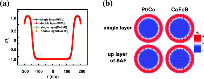
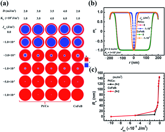
Initially, the single circular FM plate with an R of 200 nm was divided into two concentric circles. The magnetic moments of the inner one with a radius of 170 nm were set to be along the +z axis, while the remaining were along the −z direction. A stable skyrmion was generated after the initial relaxation. The temporal energy indicates that total energy decreases with time and becomes almost constant after relaxing for shorter than 1 ns. The relaxation lasted as long as 10 ns, which ensures that the skyrmion is stable enough, and a typical large skyrmion with a radius (Rs) of 165 nm was generated. The moments inside are parallel to the +z direction, which is also the orientation of the magnetic moments in the lower pinned FM layer. This is named a ferromagnetic skyrmion that is more stable in energy than its antiferromagnetic counterpart, i.e., the moments inside the skyrmion are antiparallel to those in the lower pinned FM layer (S2 in the ESI†). The moment orientation changes drastically from the +z to −z direction across a Néel-type DW at the boundary of the skyrmion. The canting of moments near the edge of the plate is due to the DMI-relevant edge effect.26 Even though the radius of the skyrmion is as large as 165 nm, it is still stabilized by DMI and different from the so-called skyrmion bubble that is generated in the system with very weak DMI.32 For a comparison, we also performed the same simulation of the upper layer (the KU values of Pt/Co and CoFeB are 4 × 10⁵ J m−3 and 1 × 10⁵ J m−3, respectively, and D = 3.5 mJ m−2) of the SAF with Jex = 0. The structure of the skyrmion in this SAF is almost the same as its counterpart in the single FM layer (Fig. 2). Therefore, the stray field from the ultrathin lower layer of the SAF had little impact on the structure of the skyrmion. On the other hand, the size of the skyrmion for Pt/Co and CoFeB is almost identical.When Jex is considered, the large skyrmion is converted into a small one while increasing Jex (Fig. 3(a)), yet the influence of D and KU in a wide range (D = 2–4 mJ m−2 and KU = 1 × 10⁵ to 6 × 10⁵ J m−3) is negligible. When the D is higher than 4 mJ m−2, the skyrmion will be destabilized and transformed into a vortex.26 This confirms that the influence of voltage-induced variations of anisotropy on the Rs can be neglected. It is also noticed that the Rs of the skyrmion reduces mainly under the weak interlayer exchange coupling when the Jex is between −1.0 × 10⁻⁶ J m−2 and −3.0 × 10⁻⁶ J m−2. With a stronger interlayer coupling, the Rs is greatly reduced to <30 nm. When Jex is weaker than −1.0 × 10⁻⁵ J m−2 or stronger than −5.0 × 10⁻⁵ J m−2, the Rs of the skyrmion for Pt/Co and CoFeB is very close. In between, the size of CoFeB is a little larger than that of Pt/Co. For applications, the effective manipulation of Rs by Jex indicates the possibility of tuning the device behavior under a low electric field. This is good for reducing dissipation, and it will be discussed in detail below.
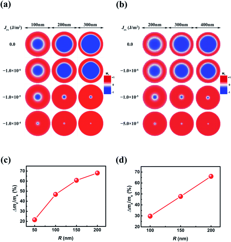
In addition to dissipation, the device size is another important factor for applications. The transition between a large skyrmion and a small one in the circular plates with different R (50–200 nm) was also simulated (Fig. 4). In all plate sizes, the Rs of skyrmions decreases mainly when Jex is between −1.0 × 10⁻⁶ J m−2 and −1.0 × 10⁻⁵ J m−2, which is not dependent on the plate size. To characterize the resistance variations of an MTJ, we consider the relative variations of the area of skyrmions with Jex increasing from 0 to −1.0 × 10⁻⁴ J m−2 (−5.0 × 10⁻⁵ J m−2) for Pt/Co (CoFeB). This is reflected in the relative change of net magnetization in the upper layer, which is defined as ΔMz/MS, where ΔMz is the change of magnetization in the transition, and MS is the saturation magnetization. This ΔMz/MS is reduced with decreasing R. However, as to Pt/Co, when R is larger than 100 nm, it is still larger than 50%. For CoFeB, to obtain ΔMz/MS that is larger than 50%, R needs to be increased to >150 nm.
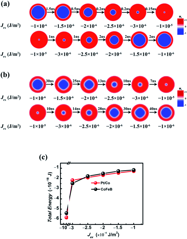
To accelerate the computing speed, the relaxation time (τ) for stabilizing a large/small skyrmion due to the variation of Jex should be considered (Fig. 5). Initially, a stable skyrmion with Jex = −1.0 × 10⁻⁶ J m−2 was generated in a circular plate with R = 200 nm and with the relaxation lasting for as long as 10 ns. Then, the τ versus Jex ranging from −1.0 × 10⁻⁶ J m−2 to −1.0 × 10⁻⁵ J m−2 was recorded. The τ for Pt/Co and CoFeB is quite different. For Pt/Co, the τ in this process is 2 ns or shorter, which means the device has a high response speed under an ultrashort voltage pulse. Nevertheless, the τ of CoFeB is longer than 10 ns, but the τ of tens of ns is still very fast for neuromorphic computing. On the other hand, the relaxation time for increasing Rs is longer than that for reducing Rs, which originates from the variation of total free energy with Jex (Fig. 5(b)). The enhancement of RKKY interaction results in a decrease in energy, which corresponds to a faster relaxation process.
Theoretical analysis
In theory, every stable skyrmion with different Rs corresponds to the state with the minimum free energy of the SAF. For a large skyrmion, the free energy densities including exchange (Eexch), uniaxial magnetic anisotropy (Eanis), DMI (EDMI), demagnetization (Ed), RKKY (ERKKY), and edge energy (Eedge) are expressed as:33with
 , and
, and | (1) |
 | (2) |
| EDMI = −2π2Drt; | (3) |
| Ed = −2πμ0MS2I(d)rt2 |
 | (4) |
| ERKKY = 2πJr2; | (5) |
| Eedge = kr2t. | (6) |
The total free energy (E) is the summation from (1) to (6), and the Rs for a stable skyrmion is obtained by resolving the equation with r as a variable:
 | (7) |
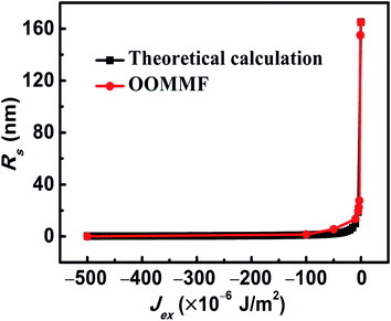 | ||
| Fig. 6 Comparison of Rs variations of skyrmions with Jex by theoretical analysis and simulations by OOMMF. | ||
The nanodevices for neuromorphic computing based on voltage-induced transition between a large skyrmion and a small one
Based on the results of the simulations, we propose a spintronic memristor composed of a CoFeB MTJ deposited on a PMN-PT piezoelectric substrate. The free layer of the MTJ is the upper layer of the SAF. The parameters are the same as those shown in Fig. 5, and the Jex is tuned between −1.0 × 10⁻⁶ J m−2 and −1.0 × 10⁻⁵ J m−2 (Fig. 7). The maximum tunneling magnetoresistance (TMR) of the MTJ is assumed to be 200%. In the upper layer of the SAF, the percentage of the area of skyrmions with respect to that of the plate is assumed to be x, and the relationship between TMR and x is assumed to satisfy a linear function.34 The TMR increases from around 60% to very close to 200% with Jex increasing from −1.0 × 10⁻⁶ J m−2 to −5.0 × 10⁻⁵ J m−2. In a device for neuromorphic computing, this continuous variation of resistance under varying voltage may mimic the potentiation or depression function of a synapse.14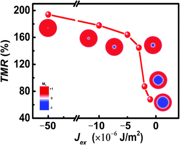 | ||
| Fig. 7 Variations of resistance in the transition between a large skyrmion and a small one with change of Jex for CoFeB (D = 2 mJ m−2 and KL = 1 × 10⁵ J m−3). | ||
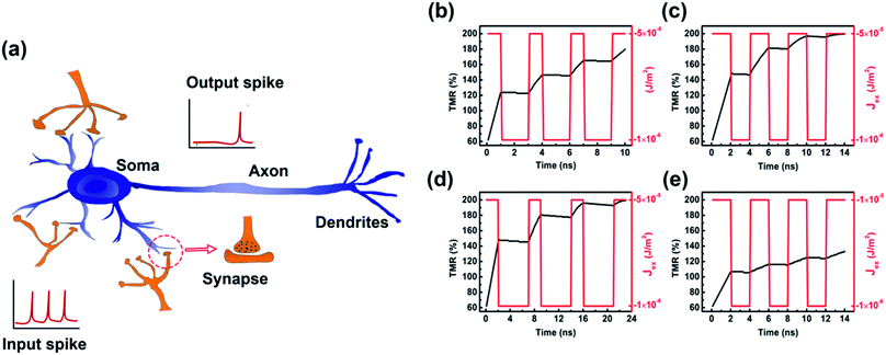
In addition to synapses, the LIF in a neuron (Fig. 8) also plays a significant role in the neuromorphic computing. In a real biological neural network, under the incoming sequence of spike pulses, the potential of cellular membranes (Vm) of a nonfiring neuron keeps increasing due to the accumulation of charges till it reaches a threshold value, triggering the firing of the neuron.15,16 This LIF function can be well mimicked based on our model. Applying a voltage pulse results in Jex alternating between two values. Because of the different relaxation time for expanding and shrinking of the skyrmion (Fig. 5), the size of the skyrmion shows an oscillating increase with increasing resistance. This process is analogous to the increasing of Vm under the spike pulse. Finally, the skyrmion is totally annihilated, representing the firing. To repeat this process, the skyrmion can be recreated in a reset process. This skyrmion-based LIF model in an SAF has been simulated. The characteristics of the firing process can be well tuned by modifying the width and magnitude of the pulse (Fig. 8(b–e)). Under a suitable condition, the firing occurs within around 10 ns.
Finally, the electric field strength and dissipation for the neuromorphic computing are estimated according to the experimental results of the manipulation of RKKY exchange coupling in the CoFeB/Ru/CoFeB SAF by electric field.25 When the electric field is absent, Jex is assumed to be −1.0 × 10⁻⁵ J m−2 by choosing a suitable thickness of the nonmagnetic layer. According to the slope of the variation of Jex with respect to electric field strength (E) (2.2 × 10⁻⁵ (J m−2)/(kV cm−1)),25 the electric field strength for reducing Jex from −1.0 × 10⁻⁵ J m−2 to −1.0 × 10⁻⁶ J m−2 should be around 0.4 kV cm−1. This electric field strength is true since the experimental results indicate that the slope of Jex to E is generally suitable to different signs and strengths of the RKKY coupling constant in the CoFeB/Ru/CoFeB SAF multilayer.25 This electric field is too weak to tune the magnetic anisotropy constant but can effectively manipulate Jex so that a small skyrmion can be converted into a large one, and vice versa (the influence of electric field on the magnetic anisotropy constant is estimated quantitatively in the ESI (S1)†). To estimate the dissipation, we consider a circular PMN-PT substrate with R = 200 nm and the thickness t = 100 μm. Based on the relative dielectric constant of PMN-PT (3000)35 and E = 0.4 kV cm−1, the dissipation for the transition between a large skyrmion and a small one is estimated to be as small as 3 × 10⁻¹⁶ J (0.3 fJ). On the other hand, unlike the temporal dissipation from current, the dissipation under a static electric field will not accumulate with time.
Summary and outlook
In conclusion, the transition between a large skyrmion and a small one based on the varying interlayer RKKY antiferromagnetic coupling was studied. This transition mainly occurs in a small range of weak RKKY exchange coupling and is not sensitive to the parameters such as DMI and magnetic anisotropy. Since the RKKY exchange coupling of a CoFeB SAF can be modulated by the multiferroic behavior, the highly efficient voltage control of RKKY exchange coupling is proved, giving rise to build skyrmion-based nanodevices for neuromorphic computing with ultralow energy consumption, including the potentiation/depression of a synapse and the LIF of a neuron. These results unveil the potential for developing a novel artificial neural network device with a small size, a high computing speed, and ultra-low dissipation. Therefore, further experimental investigation is much needed. Especially, in addition to the voltage control of RKKY coupling, the generation and current-induced motion of skyrmions in an SAF has also been realized successfully in experiments very recently.31,36,37 On the other hand, when compared to CoFeB, the artificial synapse based on Pt/Co seems to have advantages such as high computing speed due to its small damping. However, the experimental work on voltage-induced manipulation of RKKY in the Pt/Co SAF has not been reported. Last but not least, as to a real device for applications, the stability of skyrmions under thermal fluctuation or external magnetic field also needs to be considered very carefully.38,39 This also deserves further investigation.Conflicts of interest
There are no conflicts to declare.Acknowledgements
The authors would like to acknowledge the financial support from the National Natural Science Foundation of China (No. 51971098, 11774270, 11474225, and 61674062) and the Huazhong University of Science and Technology (No. 2017KFYXJJ037).References
- M. Prezioso, F. Merrikh-Bayat, B. D. Hoskins, G. C. Adam, K. K. Likharev and D. B. Strukov, Nature, 2015, 521, 61–64 CrossRef CAS PubMed.
- T. Tuma, A. Pantazi, M. L. Gallo, A. Sebastian and E. Eleftheriou, Nat. Nanotechnol., 2016, 11(8), 693–699 CrossRef CAS.
- G. W. Burr, R. W. Shelby, S. Sidler, C. di Nolfo, J. Jang, I. Boybat, R. S. Shenoy, P. Narayanan, K. Virwani, E. U. Giacometti, B. N. Kurdi and H. Hwang, IEEE Trans. Electron Devices, 2015, 62, 3498–3507 Search PubMed.
- S. Boyn, J. Grollier, G. Lecerf, B. Xu, N. Locatelli, S. Fusil, S. Girod, C. Carretero, K. Garcia, S. Xavier, J. Tomas, L. Bellaiche, M. Bibes, A. Barthelemy, S. Saighi and V. Garcia, Nat. Commun., 2017, 8, 14736 CrossRef.
- J. Torrejon, M. Riou, F. A. Araujo, S. Tsunegi, G. Khalsa, D. Querlioz, P. Bortolotti, V. Cros, K. Yakushiji, A. Fukushima, H. Kubota, S. Yuasa, M. D. Stiles and J. Grollier, Nature, 2017, 547, 428–431 CrossRef.
- M. Romera, P. Talatchian, S. Tsunegi, F. A. Araujo, V. Cros, P. Bortolotti, J. Trastoy, K. Yakushiji, A. Fukushima, H. Kubota, S. Yuasa, M. Ernoult, D. Vodenicarevic, T. Hirtzlin, N. Locatelli, D. Querlioz and J. Grollier, Nature, 2018, 563, 230–234 CrossRef.
- S. Li, W. Kang, X. Chen, J. Bai, B. Pan, Y. Zhang and W. Zhao, 2018 IEEE Computer Society Annual Symposium on VLSI, 2018, pp. 539–544 Search PubMed.
- A. Sengupta, Y. Shim and K. Roy, IEEE Trans. Biomed. Circuits Syst., 2016, 10, 1152–1160 Search PubMed.
- M. Sharad, C. Augustine, G. Panagopoulos and K. Roy, IEEE Trans. Nanotechnol., 2012, 11, 843–853 Search PubMed.
- J. Grollier, D. Querlioz and M. D. Stiles, Proc. IEEE, 2016, 104, 2024–2039 Search PubMed.
- P. Krzysteczko, J. Munchenberger, M. Schafers, G. Reiss and A. Thomas, Adv. Mater., 2012, 24, 762–766 CrossRef CAS.
- S. Lequeux, J. Sampaio, V. Cros, K. Yakushiji, A. Fukushima, R. Matsumoto, H. Kubota, S. Yuasa and J. Grollier, Sci. Rep., 2016, 6, 31510 CrossRef PubMed.
- N. Locatelli, V. Cros and J. Grollier, Nat. Mater., 2014, 13, 11–20 CrossRef.
- Y. Huang, W. Kang, X. Zhang, Y. Zhou and W. Zhao, Nanotechnology, 2017, 28, 08LT02 CrossRef.
- K. M. Song, J.-S. Jeong, S. K. Cha, T.-E. Park, K. Kim, S. Finizio, J. Raabe, J. Chang, H. Ju and S. Woo, arXiv preprint arXiv:1907.00957, 2019.
- X. Chen, W. Kang, D. Zhu, X. Zhang, N. Lei, Y. Zhang, Y. Zhou and W. Zhao, Nanoscale, 2018, 10, 6139–6146 RSC.
- A. Kurenkov, S. DuttaGupta, C. Zhang, S. Fukami, Y. Horio and H. Ohno, Adv. Mater., 2019, 1900636 CrossRef.
- W. Eerenstein, N. D. Mathur and J. F. Scott, Nature, 2006, 442, 759–765 CrossRef.
- X. Yang, Z. Zhou, T. Nan, Y. Gao, G. M. Yang, M. Liu and N. X. Sun, J. Mater. Chem. C, 2016, 4, 234–243 RSC.
- J. M. Hu, L. Q. Chen and C. W. Nan, Adv. Mater., 2016, 28, 15–39 CrossRef.
- S. Li, W. Kang, Y. Huang, X. Zhang, Y. Zhou and W. Zhao, Nanotechnology, 2017, 28, 31LT01 CrossRef.
- Q. Yang, T. Nan, Y. Zhang, Z. Zhou, B. Peng, W. Ren, Z.-G. Ye, N. X. Sun and M. Liu, Phys. Rev. Appl., 2017, 8, 044006 CrossRef.
- B. Peng, Z. Zhou, T. Nan, G. Dong, M. Feng, Q. Yang, X. Wang, S. Zhao, D. Xian, Z.-D. Jiang, W. Ren, Z.-G. Ye, N. X. Sun and M. Liu, ACS Nano, 2017, 11, 4337–4345 CrossRef.
- S. Luo, N. Xu, Z. Guo, Y. Zhang, J. Hong and L. You, IEEE Electron Device Lett., 2019, 40, 635–638 Search PubMed.
- X. Wang, Q. Yang, L. Wang, Z. Zhou, T. Min, M. Liu and N. X. Sun, Adv. Mater., 2018, 1803612 CrossRef.
- S. Rohart and A. Thiaville, Phys. Rev. B: Condens. Matter Mater. Phys., 2013, 88, 184422 CrossRef.
- J. Sampaio, V. Cros, S. Rohart, A. Thiaville and A. Fert, Nat. Nanotechnol., 2013, 8, 839–844 CrossRef CAS.
- S. Iihama, Q. Ma, T. Kubota, S. Mizukami, Y. Ando and T. Miyazaki, Appl. Phys. Express, 2012, 5, 083001 CrossRef.
- H. Yang, A. Thiaville, S. Rohart, A. Fert and M. Chshiev, Phys. Rev. Lett., 2015, 115, 267210 CrossRef.
- S. H. Yang, K. S. Ryu and S. Parkin, Nat. Nanotechnol., 2015, 10, 221–226 CrossRef CAS.
- T. Dohi, S. DuttaGupta, S. Fukami and H. Ohno, Nat. Commun., 2019, 10, 1–6 CrossRef CAS.
- W. Jiang, P. Upadhyaya, W. Zhang, G. Yu, M. B. Jungfleisch, F. Y. Fradin, J. E. Pearson, Y. Tserkovnyak, K. L. Wang, O. Heinonen, S. G. E. te Velthuis and A. Hoffmann, Science, 2015, 349, 283–286 CrossRef CAS.
- A. Bernand-Mantel, L. Camosi, A. Wartelle, N. Rougemaille, M. Darques and L. Ranno, SciPost Phys., 2018, 4, 027 CrossRef.
- S. Luo, Y. Zhang, M. Shen, J. Ou-Yang, B. Yan, X. Yang, S. Chen, B. Zhu and L. You, Appl. Phys. Lett., 2017, 110, 112402 CrossRef.
- S. W. Choi, R. T. R. Shrout, S. J. Jang and A. S. Bhalla, Ferroelectrics, 1989, 100, 29–38 CrossRef CAS.
- Y. Li, Q. Feng, S. Li, K. Huang, M. Ma, W. Gan, H. Zhou, X. Jin, X. Renshaw Wang, Y. Lu, W. S. Lew, Q. Lu and F. Ma, Adv. Funct. Mater., 2019, 30, 1907140 CrossRef.
- W. Legrand, D. Maccariello, F. Ajejas, S. Collin, A. Vecchiola, K. Bouzehouane, N. Reyren, V. Cros and A. Fert, Nat. Mater., 2020, 19, 34–42 CrossRef CAS.
- R. Tomasello, K. Y. Guslienko, M. Ricci, A. Giordano, J. Barker, M. Carpentieri, O. Chubykalo-Fesenko and G. Finocchio, Phys. Rev. B, 2018, 97, 060402(R) CrossRef.
- F. Buttner, I. Lemesh and G. S. D. Beach, Sci. Rep., 2018, 8, 4464 CrossRef.
Footnotes |
| † Electronic supplementary information (ESI) available. See DOI: 10.1039/d0na00009d |
| ‡ The author who has the same contribution as Ziyang Yu. |
| This journal is © The Royal Society of Chemistry 2020 |


