Metal-free highly efficient photocatalysts for overall water splitting: C3N5 multilayers†
Siyun
Qi
,
Yingcai
Fan
 ,
Junru
Wang
,
Xiaohan
Song
,
Weifeng
Li
and
Mingwen
Zhao
,
Junru
Wang
,
Xiaohan
Song
,
Weifeng
Li
and
Mingwen
Zhao
 *
*
School of Physics and State Key Laboratory of Crystal Materials, Shandong University, Jinan, Shandong, China. E-mail: zmw@sdu.edu.cn
First published on 18th November 2019
Abstract
As a promising means of renewable energy storage, the production of molecular hydrogen and oxygen from photocatalytic water splitting has gained increasing interest. The optimal photocatalyst for water splitting should have high solar energy conversion efficiency and strong photocatalytic redox ability to drive the hydrogen evolution reaction (HER) and oxygen evolution reaction (OER). However, few photocatalysts have been reported to fulfil these two contradictive requirements. Here, we demonstrated from first-principles calculations that the recently synthesized two-dimensional carbon nitride (C3N5) multilayers can serve as promising candidates to reach this goal. The intrinsic electric field which is more pronounced in the multilayers alters the band alignment of the photocatalysts, making the HER and OER be driven solely by the photogenerated carriers. The thickness-dependent electronic band gap (2.95–2.16 eV) along with the high carrier mobility broadens the energy range of light absorption and promotes carrier separation and transfer, leading to high solar energy conversion efficiency. Our computational results offer not only low-cost, Earth-abundant and environmentally friendly photocatalysts but also a promising strategy for the design of photocatalysts for highly efficient overall water splitting without using sacrificial reagents.
Introduction
With the exploration of energy and environment, solar energy has become one of the focuses of current research as a clean and renewable source of energy that ensures sustainable development of human society.1–3 Photocatalytic water splitting into H2 and O2 that directly converts solar energy into hydrogen fuel has been attracting growing interest since the pioneering work of Fujishima and Honda.4 To match the potentials of hydrogen reduction H+/H2 (−4.44 eV) and water oxidation H2O/O2 (−5.67 eV), the photocatalyst should have an electronic band gap larger than 1.23 eV.5,6 But a larger band gap would lead to a lower solar energy conversion efficiency.7,8 In addition, the photogenerated electrons and holes in the photocatalysts should be capable of fast separation and migration to suppress their recombination; otherwise the energy conversion efficiency will be greatly reduced.9,10 The lowest solar-to-hydrogen (STH) efficiency that makes photocatalysts economically viable is about 10%.11,12Another challenging issue that the current photocatalysts are facing is the need for sacrificial reagents.13,14 Photocatalytic water splitting contains two half-reactions, i.e., the hydrogen evolution reaction (HER) and oxygen evolution reaction (OER). The redox ability of the photogenerated carriers for the HER (or OER) can be determined by the energy difference between the conduction band minimum (or valence band maximum) and the hydrogen reduction potential H+/H2 (or water oxidation potential, O2/H2O). To trigger the overall water splitting, the overpotential of the photogenerated electrons (and holes) should be higher than that of the HER (and OER), otherwise, sacrificial agents are needed to keep the whole reaction running.15 Notably, improving the redox ability of photogenerated carriers and increasing the energy conversion efficiency are two contradictive goals in a sense.16,17 High photocatalytic redox ability requires a large band gap, whereas high energy conversion efficiency is always correlated to a narrow band gap to broaden the light absorption range. Therefore, a compromise between the energy conversion efficiency and redox ability is crucial for highly efficient photocatalysts for overall water splitting and becomes the focus of recent studies.18 For example, on the basis of first-principles calculations, Li et al. predicted that the redox ability of the photogenerated electrons and holes in the PdSeO3 monolayer is high enough to drive both the HER and OER in water without using sacrificial reagents.19 Unfortunately, the PdSeO3 monolayer has a relatively large band gap of ∼2.84 eV, which is unfavorable for high energy conversion efficiency.
Very recently, a new mechanism for photocatalytic water splitting has been proposed and has gained increasing interest.20 In this mechanism, the intrinsic electric field (EF) of the photocatalyst alters the band alignments and breaks the band gap limitation (1.23 eV) for overall water splitting. The EF also accelerates the separation of the photoexcited electrons and holes and suppresses their rapid recombination. Guided by this new mechanism, a number of materials have been proposed for overall water splitting, such as Janus chalcogenide layers,21 germanium monochalcogenide monolayer22 and Sc2CO2.23 However, the redox ability for the HER and OER of these photocatalysts has rarely been investigated. Despite the experimental progress in photocatalytic overall water splitting, extensive theoretical studies on this new mechanism are timely and desirable.
Two-dimensional (2D) carbon nitrides (C3N4) have been demonstrated to be promising photocatalysts for overall water splitting, due to their structural stability, low cost, easy synthesis, environmental friendliness, etc.24,25 However, the OER overpotential of the C3N4 catalysts is too high to be overcome solely by the voltage generated by the photogenerated electrons.26 Although considerable efforts have been made to reduce the OER overpotential of C3N4 catalysts, e.g., by doping transition metal atoms,27,28 replacing the N atom with a S atom,29 and forming heterostructures with other 2D materials,30,31 improving the photocatalytic performance of the C3N4 catalysts remains a challenging task.
In this work, we demonstrated that the conflict between high broad range light absorption (high energy conversion efficiency) and high photocatalytic redox ability for the HER and OER can be resolved by the intrinsic EF effect. Based on first-principles calculations, we propose a promising candidate 2D material, a C3N5 multilayer,32 to realize this mechanism. Our calculations showed that the intrinsic EF in the C3N5 multilayer leads to spatial separation of the valence band maximum (VBM) and conduction band minimum (CBM), suppressing the recombination of the photogenerated carriers. Meanwhile, high carrier mobility also facilitates the migration and thus the separation of the carriers. The band alignment of the C3N5 multilayer can be modulated by the thickness, enabling a narrow band gap and high redox ability of the photogenerated carriers. Both the HER and OER can proceed, driven solely by the potential of the photogenerated carriers. High STH efficiency with the upper limit up to 12.35% due to broad band solar absorption is predicted in these metal-free carbon nitride photocatalysts. Our theoretical results propose not only a low-cost, Earth-abundant and environmentally friendly photocatalyst but also a general strategy for the design of highly efficient photocatalysts for overall water splitting without using sacrificial reagents.
Computational methods
Our first-principles calculations were performed using the Vienna ab initio simulation package (VASP) within the framework of density functional theory (DFT).33 The electron–ion interaction was described by the projector-augmented wave (PAW) potential.34 The generalized gradient approximation (GGA) in the form of the Perdew–Burke–Ernzerhof (PBE) functional was adopted for the exchange–correlation functional.35,36 The van der Waals (vdW) interactions were taken into account by using the DFT-D3 functional, which reproduced well the experimental data of the lattice constants.37 The HSE06 hybrid functional was adopted to give more reliable electronic band structures, band alignment and light absorption properties.38 The Kohn–Sham electron-wave functions were expanded using the plane-wave functions with an energy cutoff of 520 eV. The energy convergence was set to 10−5 eV and the residual force was set to 0.01 eV Å−1. Brillouin zone (BZ) integration was carried out using 7 × 7 × 1 k-point meshes.39 A vacuum space of more than 20 Å was applied in the z-direction to eliminate interactions between neighboring images. For the electrocatalytic reaction calculations, we used a 2 × 2 supercell to avoid the effects of the adjacent intermediates. The formation energy of the C3N5 monolayer was calculated by: Ef = E(C3N5) − (mμC + nμN), where E(C3N5) is the total energy of the C3N5 monolayer, and m and n are the number of carbon and nitrogen atoms in one unit cell, respectively. μC and μN are the chemical potentials of carbon and nitrogen atoms, which were obtained from graphene and N2, respectively. The photon spectra were calculated using the VASP code interface by the Phonopy code.40Ab initio molecular dynamics (AIMD) simulations were carried out in the canonical ensemble (NVT) with a time step of 1.0 fs.41The Gibbs free energy (ΔG) of the HER and OER was evaluated using the standard hydrogen electrode model proposed by Nørskov et al. for the elemental step, as follows:42,43
| ΔG = ΔE + ΔEzpe − TΔS + ΔGU + ΔGpH |
The OER process in the acidic aqueous solution involves four-electron oxidation steps, which can be written as:44
| H2O + * → OH* + H+ + e− |
| OH* → O* + H+ + e− |
| O* + H2O → OOH* + H+ + e− |
| OOH* → * + O2 (g) + H+ + e− |
| * + H+ + e− → H* |
| H* + H+ + e− → * + H2 (g) |
The STH efficiency of the photocatalyst QSTH can be evaluated approximately by using the following expression:13
Results and discussion
For the non-polar photocatalysts without intrinsic EF, the band gap required for overall water splitting should be larger than 1.23 eV, because both the hydrogen reduction potential (VH = −4.44 eV) and water oxidation potential (VO = −5.67 eV) should be located inside the band gap, as shown in Fig. 1(a). In this case, the hydrogen reduction potential and water oxidation potential are aligned with respect to the VBM and CBM according to the same vacuum level which can be determined from the average electrostatic potential of the photocatalysts. Then the redox ability of the photogenerated electrons (or holes) can be evaluated by the energy difference between the CBM (or VBM) and the hydrogen reduction potential, which is denoted as Ue (or Uh), as shown in Fig. 1(a). Here, Ue and Uh correspond to the potential of the photogenerated electrons and holes, respectively. To trigger the HER and OER, they should fulfill the following conditions: Ue ≥ ηHER and Uh ≥ ηOER + 1.23, where ηHER and ηOER represent the overpotentials of the HER and OER. The ideal photocatalyst for water splitting has ηHER = 0 and ηOER = 0, corresponding to the lower limit of band gap of 1.23 eV due to the constraint of Eg = Ue + Uh.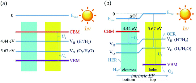 | ||
| Fig. 1 The schematic representation of the water splitting mechanisms for the photocatalysts (a) without and (b) with the intrinsic EF effect. | ||
For the polar 2D photocatalysts with out-of-plane intrinsic EF, the mechanism for photocatalytic overall water splitting differs significantly from the above case. Let us suppose that the intrinsic EF points from the bottom surface to the top surface, as shown in Fig. 1(b). Driven by the EF, the photogenerated electrons and holes migrate to the bottom and top surfaces of the photocatalysts, ensuring that the HER and OER proceed, respectively, on these surfaces.45–47 Notably, the vacuum levels are no longer equivalent in the top and bottom regions, but exhibit a difference due to the intrinsic EF effect. The photocatalytic redox ability of the top and bottom surfaces should be evaluated with respect to the vacuum levels of the two regions, as indicated in Fig. 1(b). In this case, the constraint of the band gap becomes Eg = Ue + Uh − ΔΦ. Therefore, high photocatalytic redox ability represented by large Ue and Uh can be achieved in materials with a small band gap.
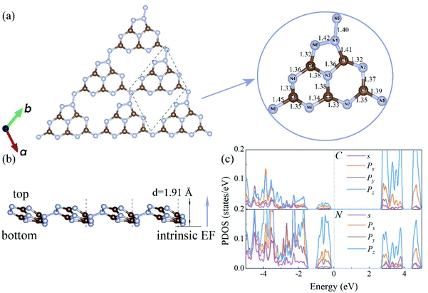
To realize the above mechanism, we considered the candidate materials, C3N5 multilayers, which have been synthesized in recent experiments.34 The C3N5 monolayer is composed of triazoles and triazines forming a 2D monoclinic lattice, as shown in Fig. 2. The optimized lattice parameters are a = 5.64 Å, b = 6.68 Å, and γ = 113°, consistent with the experimental data.32 There are four types of nitrogen atoms in the framework: sp3-hybridized nitrogen (N1 and N5), pyridine nitrogen (N2, N4, N6 and N7), pyrrole nitrogen (N8) and graphic nitrogen (N3). The presence of sp3-hybridized nitrogen atoms results in the buckling of the lattice with a buckled height of 1.91 Å. The N–N bond length between the two sp3-hybridized nitrogen atoms (N1–N5) is about 1.40 Å, slightly shorter than that (N1–N8) in the triazole (1.42 Å). The lengths of the C–N bonds are in the range from 1.32 Å to 1.45 Å, which are very close to the values of C3N4 (1.33 and 1.39 Å)24 and C2N (1.34 Å).48 The formation energy of the C3N5 monolayer (−2.39 eV per atom) obtained from our calculations is very close to that of the C3N4 monolayer (−2.47 eV per atom), indicating the energetic stability of the C3N5 monolayer. The phonon spectrum and AIMD simulations also confirmed the dynamic and thermodynamic stability of the C3N5 monolayer, as shown in Fig. S1.† Although the formation energy of the C3N4 monolayer is slightly lower than that of the C3N5 monolayer, we didn't find any tendency of conversion from the C3N5 monolayer to the C3N4 monolayer in our AIMD simulations. Notably, the absence of inversion symmetry and electron transfer between carbon and nitrogen atoms induce out-of-plane electric polarization and intrinsic EF, which are expected to affect the band alignment and relevant electronic properties.
We determined the energetically most preferable structure of the C3N5 bilayer from different stacking patterns and found that it favors a slightly shifted AA-like stacking pattern of monolayers, in good agreement with the results of a previous study.32 Such a slightly shifted AA-like pattern guarantees an improved intrinsic EF effect. Following this stacking pattern, we constructed C3N5 multilayers containing two, three, four and five monolayers. The exfoliation energy of a C3N5 monolayer from the multilayers was evaluated to be about 13.2 meV Å−2, which is much smaller than the existing single-layer 2D materials, such as graphene (21 meV Å−2), h-BN (32 meV Å−2)49 and C3N4 (36 meV Å−2),50 as shown in Fig. S2.† These results confirm that the interlayer interactions in the C3N5 multilayers are dominated by weak vdW interactions, which verifies the peelability of the multilayer via exfoliation techniques in experiments.
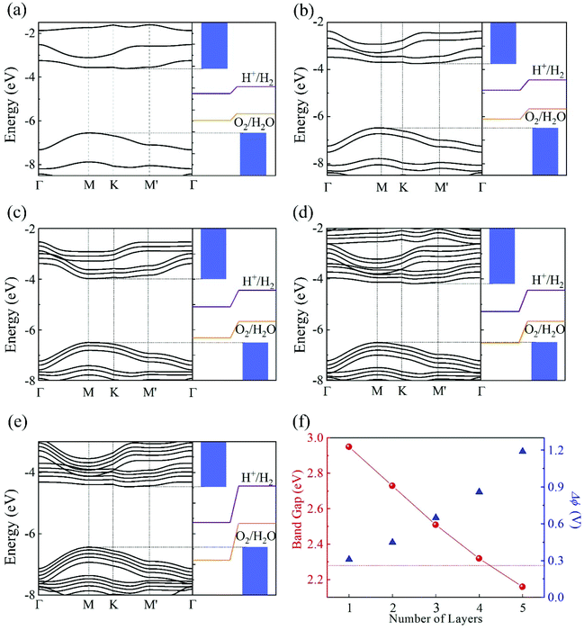
The electronic band structures of the C3N5 monolayer and multilayers were then calculated using the HSE06 functional. The electronic band structures of these C3N5 materials show that they are semiconductors with an indirect band gap ranging from 2.95 (monolayer) to 2.16 eV (five-layers), as shown in Fig. 3(a)–(e) and Table 1. The VBM resides at M (0.5, 0, 0), whereas the CBM is located between K (0.39, 0.31, 0) and M′ (0, 0.5, 0). From the PDOS shown in Fig. 2(c), one can see that the VBM and CBM are mainly derived from the pz orbitals of C and N atoms. The intrinsic EF pointing from the bottom surface to the top surface induces the electrostatic potential difference of ΔΦ between the vacuum levels on the two sides of the C3N5 nanosheets, as shown in Fig. S3.† The alignment of the hydrogen reduction potential (H+/H2) and the water oxidation potential (O2/H2O) was modified correspondingly in the bottom and top regions of the nanosheets, as shown in the right column of Fig. 3(a)–(e). More interestingly, the potential difference of the two sides (ΔΦ) increases with the increases of the thickness of the C3N5 photocatalysts, whereas the band gap exhibits an inverse trend, as shown in Fig. 3(f). We attributed this phenomenon to the synergistic effect of intrinsic EF and the quantum confinement effect.51 Such variations in the trends of ΔΦ and electronic band gap offer a promising approach to optimize the photocatalytic redox ability and energy conversion efficiency in a specific range of thickness. It should be mentioned that the intrinsic EF effect increases with the increase of thickness, which will further reduce the band gap and improve the redox ability of photogenerated carriers. However, this trend will not always continue because it will lead to the divergence of the electric potential which is obviously unphysical. With the increase of the thickness, charge redistribution, e.g., electron transfer along the inverse direction of the intrinsic electric field in response to the band structure modification, will converge the electric field effect. For the bulk C3N5 crystal that contains an infinite number of monolayers, our calculations showed that it is a semiconductor with a band gap of 2.26 eV, as indicated in Fig. S3(f).†
| Systems | Gap (eV) | EF (V) | U e (V) | η HER (V) | U h (V) | η OER (V) | Q′STH (%) |
|---|---|---|---|---|---|---|---|
| Monolayer | 2.95 | 0.31 | 1.14 | 0.76 | 2.11 | 0.71 | 2.65 |
| Bilayer | 2.73 | 0.43 | 1.12 | 0.74 | 2.03 | 0.69 | 4.54 |
| Trilayer | 2.51 | 0.65 | 1.10 | 0.75 | 2.06 | 0.68 | 7.26 |
| 4 layers | 2.32 | 0.85 | 1.11 | 0.76 | 2.06 | 0.69 | 9.94 |
| 5 layers | 2.16 | 1.19 | 1.17 | 0.79 | 1.99 | 0.69 | 12.35 |
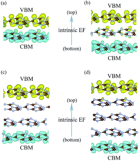
Another interesting effect of the intrinsic EF is the spatial separation of the Kohn–Sham electron wavefunctions of the VBM and CBM, which reside mainly on the top and bottom layers, as shown in Fig. 4. Therefore, the photogenerated electrons and holes will accumulate at the bottom and top layers, contributing to the HER and OER processes, respectively. This is consistent with the mechanism discussed in the beginning of this section.
The redox ability of the photogenerated carriers in the C3N5 nanosheets was then evaluated from the band alignments. The potentials of the photogenerated electrons (Ue) and holes (Uh) are listed in Table 1. Although the band gap of the C3N5 nanosheets decreases drastically from 2.95 to 2.16 eV with the increase in thickness, Ue and Uh change slightly. For the five-layer C3N5, Ue and Uh are only 0.12 V lower than those of the monolayer. This implies that the redox ability of photogenerated carriers is well preserved in the C3N5 multilayers with the decrease of the electronic band gap, which is quite crucial for achieving high photocatalytic redox ability in a small band gap semiconductor.
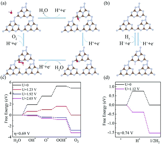
Having investigated the electronic structures of C3N5 multilayers, we then turned our attention to the two half-reactions (OER and HER) on the C3N5 photocatalysts. Our calculations showed that OH* prefers to adsorb on the C5 site of the top surface, consistent with the experimental finding that C5 has the most positive potential in the structure.32 The calculated Gibbs free energy (ΔG) diagrams of the four steps that occur at the C5 site of a C3N5 bilayer are shown in Fig. 5. Meanwhile, we also considered a two-electron process for the OER process which generates H2O2 from H2O.52 The free energy of the two-electron process ΔGH2O2 is higher than that of the four-electron process ΔGO*, as shown in Fig. S4,† suggesting that the C3N5 multilayer prefers a four-electron OER rather than a two-electron OER. Therefore, we mainly focus on the four-electron OER process in the following parts.
The 1st step of the four-electron OER has the highest ΔG value of about 1.94 eV among the four steps, corresponding to an overpotential of 0.69 V. The overpotential is much smaller than that of the C3N4 monolayer (1.56 V),26,29 implying that C3N5 nanosheets have a higher OER activity than C3N4 materials. In this case, an external voltage higher than 1.92 V is required for the OER to proceed. Fortunately, the potentials of the photogenerated holes are high enough to drive the OER. Under the electric voltage provided by the photogenerated holes (Uh = 1.99–2.11 eV), all of the four steps become downhill, as shown in Fig. 5(c), indicating that the OER process can proceed, driven solely by the photogenerated holes.
The HER prefers the N6 site of the bottom surface, as shown in Fig. 5(b). The ΔG for the HER at U = 0 is about 0.74 eV for a C3N5 bilayer, as shown in Fig. 5(d). This value is lower than the potential of the photogenerated electrons, Ue = 1.10–1.17 V, as listed in Table 1. Under the voltage (1.12 V) provided by the photogenerated electrons, the profile of the Gibbs free energies becomes downhill, as shown in Fig. 5(d), suggesting that the HER can proceed without the need for an external electric field. Therefore, both the HER and OER can proceed spontaneously driven solely by the photogenerated electrons and holes.
The thickness-dependent overpotentials of the HER and OER and the potentials of the photogenerated carriers of the C3N5 nanosheets are listed in Table 1. Clearly, the potentials of the photogenerated carriers are high enough to drive the HER and OER processes for these C3N5 photocatalysts.
High carrier mobility not only facilitates carrier migration to the surface for the subsequent HER and OER process, but also avoids the rapid combination of the photogenerated carriers. We calculated the carrier mobility of the C3N5 monolayer by using the acoustic phonon-limited scattering model. The carrier mobility can be expressed as:53
| Carrier type | m e*/m0 | m e*/m0 | E x | E y | C x | C y | μ x | μ y |
|---|---|---|---|---|---|---|---|---|
| x- | y- | (eV) | (J m−2) | (cm2 V−1 s−1) | ||||
| Electron | 1.89 | 1.82 | 1.45 | 0.52 | 54.46 | 164.36 | 161.08 | 3777.36 |
| Hole | 1.25 | 2.34 | 4.71 | 2.98 | 24.37 | 98.04 | ||
Finally, we evaluated the light absorption properties and solar energy conversion efficiencies of the C3N5 photocatalysts. Fig. 6(a) shows the optical absorption of the C3N5 monolayer and multilayers calculated at the HSE06 level. Multilayers have higher optical absorption ability than the monolayer in the visible light region, due to their reduced electronic band gaps. The first absorption peak of the C3N5 photocatalysts exhibits a clear red-shift as the thickness increases. The absorption wavelengths of the photocatalysts cover the visible-light range, which is beneficial for improving the solar energy conversion efficiency. Assuming 100% efficiency of light absorption and carrier utilization,13 the STH efficiencies of the C3N5 photocatalysts are roughly estimated to be 2.65% (monolayer), 4.54% (bilayer), 7.26% (trilayer), 10.07% (four-layer) and 12.35% (five-layer), respectively. The upper limit of the STH efficiency of these C3N5 nanosheets even exceeds the critical value (∼10%) that makes the photocatalysts economically viable. These STH efficiencies are higher than 2.6% of Al2S3 and 6.4% of Ga2S3,13 and comparable to 9.3% of WSe2/SnSe2 and 10.5% of MoSe2/SnSe2 heterostructures,56 but lower than 15.8% of InGaSSe and 21.4% of InGasTe Janus bilayers.57 However, the HER in these materials cannot be driven solely by the photogenerated carriers unless vacancy defects are introduced.56,57 In view of the recent experimental progress in the synthesis of C3N5 nanosheets,34 we believe our theoretical results will motivate the following experimental explorations on the photocatalytic overall water splitting.
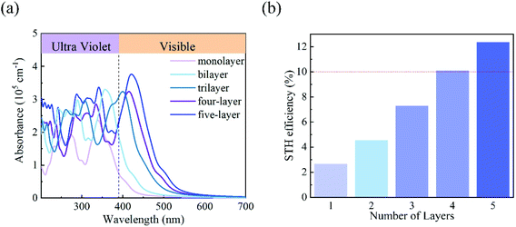 | ||
| Fig. 6 (a) The optical absorption of the monolayer and few-layered C3N5 calculated using the HSE06 functional. (b) The STH efficiency of monolayer and few-layered C3N5. | ||
Conclusion
In summary, we proposed that the intrinsic electric field in photocatalysts is available for achieving the driving forces and high solar energy conversion efficiency for overall water splitting and demonstrated promising candidate materials, C3N5 multilayers. The intrinsic out-of-plane electric field and the high carrier mobility accelerate the separation and migration of the photogenerated carriers and alter the band alignment of the photocatalysts. High photocatalytic redox ability is preserved in the C3N5 multilayers, enabling the spontaneous HER and OER in water, driven solely by the photogenerated electrons and holes. The tunable electronic band gap of the C3N5 multilayers, 2.95–2.16 eV, broadens the energy range of light absorption and leads to high solar energy conversion efficiency. Our computational results offer not only low-cost, Earth-abundant and environmentally friendly photocatalysts but also a promising strategy for the design of photocatalysts for highly efficient overall water splitting without using sacrificial reagents.Conflicts of interest
There are no conflicts to declare.Acknowledgements
This study was supported by the National Natural Science Foundation of China (No. 21833004) and the Basic Research Project of Natural Science Foundation of Shandong Province (ZR2018ZB0751).References
- M. G. Walter, E. L. Warren, J. R. McKone, S. W. Boettcher, Q. Mi, E. A. Santori and N. S. Lewis, Chem. Rev., 2010, 110, 6446–6473 CrossRef CAS PubMed.
- M. R. Hoffmann, S. T. Martin, W. Choi and D. W. Bahnemann, Chem. Rev., 1995, 95, 69–96 CrossRef CAS.
- G. Girishkumar, B. McCloskey, A. C. Luntz, S. Swanson and W. Wilcke, J. Phys. Chem. Lett., 2010, 1, 2193–2203 CrossRef CAS.
- A. Fujishima and K. Honda, Nature, 1972, 238, 37–38 CrossRef CAS PubMed.
- M. Ni, M. K. H. Leung, D. Y. C. Leung and K. Sumathy, Renewable Sustainable Energy Rev., 2007, 11, 401–425 CrossRef CAS.
- T. R. Cook, D. K. Dogutan, S. Y. Reece, Y. Surendranath, T. S. Teets and D. G. Nocera, Chem. Rev., 2010, 110, 6474–6502 CrossRef CAS PubMed.
- J. R. Bolton, S. J. Strickler and J. S. Connolly, Nature, 1985, 316, 495–500 CrossRef CAS.
- C. Xu, P. Ravi Anusuyadevi, C. Aymonier, R. Luque and S. Marre, Chem. Soc. Rev., 2019, 48, 3868–3902 RSC.
- K. Maeda and K. Domen, J. Phys. Chem. Lett., 2010, 1, 2655–2661 CrossRef CAS.
- J. Yang, D. Wang, H. Han and C. Li, Acc. Chem. Res., 2013, 46, 1900–1909 CrossRef CAS PubMed.
- L. Liao, Q. Zhang, Z. Su, Z. Zhao, Y. Wang, Y. Li, X. Lu, D. Wei, G. Feng, Q. Yu, X. Cai, J. Zhao, Z. Ren, H. Fang, F. Robles-Hernandez, S. Baldelli and J. Bao, Nat. Nanotechnol., 2013, 9, 69–73 CrossRef PubMed.
- Y. Goto, T. Hisatomi, Q. Wang, T. Higashi, K. Ishikiriyama, T. Maeda, Y. Sakata, S. Okunaka, H. Tokudome, M. Katayama, S. Akiyama, H. Nishiyama, Y. Inoue, T. Takewaki, T. Setoyama, T. Minegishi, T. Takata, T. Yamada and K. Domen, Joule, 2018, 2, 509–520 CrossRef CAS.
- C. F. Fu, J. Sun, Q. Luo, X. Li, W. Hu and J. Yang, Nano Lett., 2018, 18, 6312–6317 CrossRef CAS PubMed.
- Z. Chen, T. F. Jaramillo, T. G. Deutsch, A. Kleiman-Shwarsctein, A. J. Forman, N. Gaillard, R. Garland, K. Takanabe, C. Heske, M. Sunkara, E. W. McFarland, K. Domen, E. L. Miller, J. A. Turner and H. N. Dinh, J. Mater. Res., 2011, 25, 3–16 CrossRef.
- Z. Zou, J. Ye, K. Sayama and H. Arakawa, Nature, 2001, 414, 625–627 CrossRef CAS PubMed.
- Q. Wang, T. Hisatomi, Q. Jia, H. Tokudome, M. Zhong, C. Wang, Z. Pan, T. Takata, M. Nakabayashi, N. Shibata, Y. Li, I. D. Sharp, A. Kudo, T. Yamada and K. Domen, Nat. Mater., 2016, 15, 611–615 CrossRef CAS PubMed.
- J. Liu, Y. Liu, N. Liu, Y. Han, X. Zhang, H. Huang, Y. Lifshitz, S.-T. Lee, J. Zhong and Z. Kang, Science, 2015, 347, 970–974 CrossRef CAS PubMed.
- S. Hu, C. Xiang, S. Haussener, A. D. Berger and N. S. Lewis, Energy Environ. Sci., 2013, 6, 2984–2993 RSC.
- M. Qiao, J. Liu, Y. Wang, Y. Li and Z. Chen, J. Am. Chem. Soc., 2018, 140, 12256–12262 CrossRef CAS PubMed.
- X. Li, Z. Li and J. Yang, Phys. Rev. Lett., 2014, 112, 018301 CrossRef PubMed.
- Y. Ji, M. Yang, H. Dong, T. Hou, L. Wang and Y. Li, Nanoscale, 2017, 9, 8608–8615 RSC.
- M. Qiao, Y. Chen, Y. Wang and Y. Li, J. Mater. Chem. A, 2018, 6, 4119–4125 RSC.
- C.-F. Fu, X. Li, Q. Luo and J. Yang, J. Mater. Chem. A, 2017, 5, 24972–24980 RSC.
- B. Zhu, L. Zhang, B. Cheng and J. Yu, Appl. Catal., B, 2018, 224, 983–999 CrossRef CAS.
- G. Gao, Y. Jiao, F. Ma, Y. Jiao, E. Waclawik and A. Du, J. Catal., 2015, 332, 149–155 CrossRef CAS.
- J. Wirth, R. Neumann, M. Antonietti and P. Saalfrank, Phys. Chem. Chem. Phys., 2014, 16, 15917–15926 RSC.
- H. Li, Y. Wu, L. Li, Y. Gong, L. Niu, X. Liu, T. Wang, C. Sun and C. Li, Appl. Surf. Sci., 2018, 457, 735–744 CrossRef CAS.
- Y. Zheng, Y. Jiao, J. Chen, J. Liu, J. Liang, A. Du, W. Zhang, Z. Zhu, S. C. Smith, M. Jaroniec, G. Q. Lu and S. Z. Qiao, J. Am. Chem. Soc., 2011, 133, 20116–20119 CrossRef CAS PubMed.
- S. Lin, X. Ye, X. Gao and J. Huang, J. Mol. Catal. A: Chem., 2015, 406, 137–144 CrossRef CAS.
- W. Che, W. Cheng, T. Yao, F. Tang, W. Liu, H. Su, Y. Huang, Q. Liu, J. Liu, F. Hu, Z. Pan, Z. Sun and S. Wei, J. Am. Chem. Soc., 2017, 139, 3021–3026 CrossRef CAS PubMed.
- K. Chen, Z. Chai, C. Li, L. Shi, M. Liu, Q. Xie, Y. Zhang, D. Xu, A. Manivannan and Z. Liu, ACS Nano, 2016, 10, 3665–3673 CrossRef CAS PubMed.
- I. Y. Kim, S. Kim, X. Jin, S. Premkumar, G. Chandra, N. S. Lee, G. P. Mane, S. J. Hwang, S. Umapathy and A. Vinu, Angew. Chem., Int. Ed., 2018, 57, 17135–17140 CrossRef CAS PubMed.
- G. Kresse and J. Furthmüller, Phys. Rev. B: Condens. Matter Mater. Phys., 1996, 54, 11169–11186 CrossRef CAS PubMed.
- P. E. Blöchl, Phys. Rev. B: Condens. Matter Mater. Phys., 1994, 50, 17953–17979 CrossRef PubMed.
- J. P. Perdew, J. A. Chevary, S. H. Vosko, K. A. Jackson, M. R. Pederson, D. J. Singh and C. Fiolhais, Phys. Rev. B: Condens. Matter Mater. Phys., 1992, 46, 6671–6687 CrossRef CAS PubMed.
- J. P. Perdew, K. Burke and M. Ernzerhof, Phys. Rev. Lett., 1996, 77, 3865–3868 CrossRef CAS PubMed.
- S. Grimme, J. Comput. Chem., 2006, 27, 1787–1799 CrossRef CAS PubMed.
- J. Heyd, G. E. Scuseria and M. Ernzerhof, J. Chem. Phys., 2003, 118, 8207–8215 CrossRef CAS.
- H. J. Monkhorst and J. D. Pack, Phys. Rev. B: Solid State, 1976, 13, 5188–5192 CrossRef.
- A. Togo, F. Oba and I. Tanaka, Phys. Rev. B: Condens. Matter Mater. Phys., 2008, 78, 134106 CrossRef.
- G. J. Martyna, M. L. Klein and M. Tuckerman, J. Chem. Phys., 1992, 97, 2635–2643 CrossRef.
- J. K. Nørskov, J. Rossmeisl, A. Logadottir, L. Lindqvist, J. R. Kitchin, T. Bligaard and H. Jónsson, J. Phys. Chem. B, 2004, 108, 17886–17892 CrossRef.
- Á. Valdés, Z. W. Qu, G. J. Kroes, J. Rossmeisl and J. K. Nørskov, J. Phys. Chem. C, 2008, 112, 9872–9879 CrossRef.
- H. Xu, D. Cheng, D. Cao and X. C. Zeng, Nat. Catal., 2018, 1, 339–348 CrossRef CAS.
- M. Faraji, M. Yousefi, S. Yousefzadeh, M. Zirak, N. Naseri, T. H. Jeon, W. Choi and A. Z. Moshfegh, Energy Environ. Sci., 2019, 12, 59–95 RSC.
- K. Chang, Z. Mei, T. Wang, Q. Kang, S. Ouyang and J. Ye, ACS Nano, 2014, 8, 7078–7087 CrossRef CAS PubMed.
- Q. Lu, Y. Yu, Q. Ma, B. Chen and H. Zhang, Adv. Mater., 2016, 28, 1917–1933 CrossRef CAS PubMed.
- J. Mahmood, E. K. Lee, M. Jung, D. Shin, I. Y. Jeon, S. M. Jung, H. J. Choi, J. M. Seo, S. Y. Bae, S. D. Sohn, N. Park, J. H. Oh, H. J. Shin and J. B. Baek, Nat. Commun., 2015, 6, 6486–6492 CrossRef CAS PubMed.
- J. H. Jung, C.-H. Park and J. Ihm, Nano Lett., 2018, 18, 2759–2765 CrossRef CAS PubMed.
- X. Ma, Y. Lv, J. Xu, Y. Liu, R. Zhang and Y. Zhu, J. Phys. Chem. C, 2012, 116, 23485–23493 CrossRef CAS.
- X. Tian, J. Duan, Y. Wei, N. Feng, X. Wang, Z. Gong, Y. Du and B. I. Yakobson, Adv. Funct. Mater., 2019, 29, 1808721 CrossRef.
- Z. Li, C. Kong and G. Lu, J. Phys. Chem. C, 2015, 120, 56–63 CrossRef.
- S. Qi, X. Ma, B. Yang, L. Sun, W. Li and M. Zhao, Carbon, 2019, 149, 234–241 CrossRef CAS.
- W. Zhang, Z. Huang, W. Zhang and Y. Li, Nano Res., 2014, 7, 1731–1737 CrossRef CAS.
- S. Lu, C. Li, H. H. Li, Y. F. Zhao, Y. Y. Gong, L. Y. Niu, X. J. Liu and T. Wang, Appl. Surf. Sci., 2017, 392, 966–974 CrossRef CAS.
- Y. Fan, J. Wang and M. Zhao, Nanoscale, 2019, 11, 14836–14843 RSC.
- Y. Fan, X. Ma, J. Wang, X. Song, A. Wang, H. Liu and M. Zhao, Sci. Bull., 2019 DOI:10.1016/j.scib.2019.10.018.
Footnote |
| † Electronic supplementary information (ESI) available. See DOI: 10.1039/c9nr08416a |
| This journal is © The Royal Society of Chemistry 2020 |


