 Open Access Article
A novel cellulose/chitosan composite nanofiltration membrane prepared with piperazine and trimesoyl chloride by interfacial polymerization
Rengui Weng *ab,
Xin Huanga,
Dongqi Liaoa,
Sheng Xua,
Lei Penga and
Xinzhong Liu*ab
aCollege of Ecological Environment and Urban Construction, Fujian University of Technology, Fuzhou 350118, China. E-mail: wengrengui109@126.com
bFujian Eco-materials Engineering Research Center, Fujian University of Technology, Fuzhou 350118, China
First published on 8th January 2020
Abstract
Bamboo cellulose (BC) is one of the most abundant renewable, hydrophilic, inexpensive, and biodegradable organic materials. The cellulose membrane is one of the best materials for replacing petroleum-based polymer films used for water purification. In this study, N-methylmorpholine-N-oxide (NMMO) was used as a solvent to dissolve cellulose and chitosan, and a regenerated cellulose/chitosan membrane (BC/CSM) was prepared by phase inversion. A new kind of cellulose/chitosan nanofiltration membrane (IP-BC/CS-NFM) was obtained by the interfacial polymerization of piperazine (PIP) and trimesoyl chloride (TMC). The IP-BC/CS-NFM was characterized by Fourier transform infrared spectroscopy (FT-IR), field emission scanning electron microscopy (FE-SEM), atomic force microscopy (AFM), thermal gravimetric analysis (TGA), the retention rate, and water flux. FT-IR analysis showed that polypiperazine amide was formed. Additionally, FE-SEM and AFM showed that a uniform roughness and dense functional layer was formed on the surface of the IP-BC/CS-NFM. Furthermore, TGA analysis showed that the thermal stability of IP-BC/CS-NFM is better than that of BC/CSM. The inorganic salt retention of IP-BC/CS-NFM was measured using a membrane performance evaluation instrument, following the order R(Na2SO4) > R(MgSO4) > R(MgCl2) > R(NaCl). At a pressure of 0.5 MPa, the retention rates for NaCl, Na2SO4, MgSO4, MgCl2, Methyl Orange, and Methyl Blue were 40.26%, 71.34%, 62.55%, 53.28%, 93.65%, and 98.86%, and the water flux values were 15.64, 13.56, 14.03, 14.88, 13.28, and 12.35 L m−2 h−1, respectively. The IP-BC/CS-NFM showed better water flux and a higher rejection rate in aqueous dye-salt solutions, and had a good separation performance under different operating pressure conditions.
Introduction
Nanofiltration (NF) is a low pressure-driven membrane separation technology. It can efficiently cut off molecular weight (Mw) ranging from 200 to 1000 Da (ref. 1) and is between a reverse osmosis membrane and ultrafiltration membrane in terms of its separation performance.2,3 Over the last few decades, it has drawn great attention. Due to its ability to separate low-molecular-weight organic species and metal ions, it has been applied to dye and biochemical substance separation and purification, drinking water purification, and seawater desalination.4–6 At present, the method of interfacial polymerization is widely used in commercial nanofiltration membrane preparation. Peng et al.7 prepared a nanofiltration membrane by the interfacial polymerization of 1-ethyl-(3-3-dimethylaminopropyl) carbodiimide hydrochloride and N-hydroxysuccinimide on a polyacrylonitrile ultrafiltration membrane. Seman et al.8,9 prepared a nanofiltration membrane by the interfacial polymerization of bisphenol A and TMC on a polyether sulfone ultrafiltration membrane. Verissimo et al.10 prepared a nanofiltration membrane by the interfacial polymerization of m-phenylene diamine and trimesoyl chloride on a polyether imide ultrafiltration hollow fiber membrane. Tang et al.11 prepared a positively charged high-performance nanofiltration membrane by solvent casting chitosan with a metal–organic framework on the top surface of a polysulfone ultrafiltration support. However, these non-biodegradable petrochemical materials lead to energy waste and destruction of the ecological environment. Therefore, developing an environmentally friendly biodegradable membrane is of great significance for the ecological environment.It is vital to find ideal materials to replace petrochemical materials for membrane production. Cellulose is one of the most abundant renewable, biodegradable, and inexpensive organic materials, and is considered to be an environmentally friendly and biocompatible product. It has been used to prepare separation membranes, but the cellulose membrane has no antimicrobial properties.12 The cellulose membrane is susceptible to microbial erosion, which influences the stability and service life of the membrane. Therefore, it is necessary to make the cellulose membrane so that it has antimicrobial properties. Chitosan is a biodegradable material with antimicrobial properties.13,14 Therefore, the key issue is how to use a low-toxicity and recyclable solvent to simultaneously dissolve both types of materials.
N-Methylmorpholine-N-oxide (NMMO) is indisputably considered to be the most promising organic solvent because it is non-toxic, non-corrosive, non-volatile, easily recyclable, and environmentally friendly.15 In recent years, the use of NMMO as a cosolvent has mainly focused on cellulose/chitosan ultrafiltration membranes, blend membranes, microspheres, etc.16,17 Weng et al.18 prepared cellulose/chitosan nanofiltration membranes by carboxymethylation, but there were problems such as low water flux. To date, there have been no reports on cellulose/chitosan nanofiltration membranes obtained by interfacial polymerization.
In this study, developed a new supporting layer from bamboo cellulose and chitosan, which is simple and environmentally friendly. The main objective of this study is to establish an environmentally friendly and low cost method to prepare nanofiltration membranes from regenerated cellulose and chitosan, hope to replace petroleum polymer membrane. The cellulose and chitosan were firstly dissolved in NMMO and coated on the non-woven fabric. The BC/CSM was obtained by rinsing with water and drying. The interfacial polymeric IP-BC/CS-NFM was obtained by interfacial polymerization and characterized in terms of its chemical composition, crystalline structure, thermal stabilities, and microstructure by FT-IR, TGA, AFM, and FE-SEM, respectively. Dye removal tests were also conducted to demonstrate the improved permselectivity of the IP-BC/CS-NFM. This research explores the chemical and physical properties, permeation, and rejection of the nanofiltration membrane.
Materials and methods
Materials
Bamboo cellulose (BC) with a polymerization degree of 650 was kindly provided by Sichuan Tianzhu Bamboo Resources Development Co. Ltd. (Sichuan, China). The BC was dried overnight at 60 °C prior to dissolution. Chitosan (CS, Mw = 2 × 10⁵ Da, degree of deacetylation = 90%) was purchased from Golden-Shell Biochemical Co., Ltd. (Zhejiang, China). N-Methylmorpholine-N-oxide (NMMO) (Analytical reagent > 97%) was obtained from Tianjin Hainachuan Science and Technology Development Co., Ltd. (Tianjin, China), and propyl gallate, polyethylene glycol (PEG) (Mw = 400, 600, 800, 1000, and 2000 Da), normal hexane, Methyl Orange (327.33 g mol−1), and Methyl Blue (799.80 g mol−1) dyes were purchased from Aladdin Chemical Regent Co., Ltd., China. Piperazine (PIP) and trimesoyl chloride (TMC) were purchased from Chengdu Aikeda Chemical Reagent Co., Ltd., (Sichuan, China). Na2SO4, NaCl, MgSO4, and MgCl2 were purchased from Tianjin Fuchen Chemical Reagent Co., Ltd., (Tianjin, China). The water used in this experiment was de-ionized water.Preparation of cellulose/chitosan nanofiltration membranes
The BC/CS solution was prepared by dissolving a particular amount of cellulose and chitosan (BC/CS = 6![[thin space (1/6-em)]](https://www.rsc.org/images/entities/char_2009.gif) :
:![[thin space (1/6-em)]](https://www.rsc.org/images/entities/char_2009.gif) 1) in 86.7% NMMO aqueous solution in a flask and adding a small amount of the antioxidant propyl gallate, and the mixture was heated at 110 °C in a pumped vacuum and stirred until the BC/CS samples were completely dissolved. The BC/CS/NMMO solution with a BC/CS concentration of 6 wt% was obtained.
1) in 86.7% NMMO aqueous solution in a flask and adding a small amount of the antioxidant propyl gallate, and the mixture was heated at 110 °C in a pumped vacuum and stirred until the BC/CS samples were completely dissolved. The BC/CS/NMMO solution with a BC/CS concentration of 6 wt% was obtained.
The PET non-woven fabric was fixed onto a glass plate of coater (GBC-A4, GIST, Korea). The BC/CS/NMMO solution was poured onto non-woven fabric and moved the roll at a speed of 20 mm s−1. The membrane was immersed in a water coagulation bath at room temperature. Then, the membrane was washed with water to remove residual solvent. Finally, the membrane was air-dried at room temperature to obtain porous network BC/CSM structures.
The range of concentration of PIP solution was 0.5 wt% to 3 wt%, and the range of TMC solution was 0.05 wt% to 0.3 wt%, there were prepared by deionized water and n-hexane, respectively. The BC/CSM was fixed in the interfacial polymerization reactor. Firstly, the range of concentration of PIP solution was added to the device, after soaking for the range of time (10 min to 60 min), and the PIP solution was poured out and left to dry. Secondly, the range of concentration of TMC solution was added to the device, after interfacial polymerization for the range of time (0.5 min to 3 min), and the organic phase solution was quickly discharged. Finally, the polymerization layer was naturally dried, and IP-BC/CS-NFM was obtained (Fig. 1).
Characterization of cellulose/chitosan nanofiltration membranes
The BC/CSM and IP-BC/CS-NFM were tested by Fourier transform infrared spectroscopy (FT-IR). The spectra with a wave number ranging from 4000 to 400 cm−1 were recorded on a Fourier Transform Infrared spectrometer (Thermo Nicolet 380) by the KBr-disk method.The surface and cross-sectional morphology of BC/CSM and IP-BC/CS-NFM were investigated with an FEI Nova NanoSEM450 field emission scanning electron microscope (FE-SEM). Atomic force microscopy(AFM) imaging of membranes with noncontact mode was performed with an Agilent 5500 AFM/SPM microscope (Agilent Technologies). The samples were freeze-fractured in liquid nitrogen, followed by sputtering with gold in a sputtering device.
The material mass loss relationship with change of temperature was determined with a thermal gravimetric analysis (TGA) instrument (Netzsch STA 449 F3) at the heating rate of 10 °C min−1 under nitrogen with a flow rate of 20 mL min−1. Each sample weighed about 2 to 3 mg as a standard and was heated from 30 to 600 °C.
Cross-flow permeation tests
Permeation tests for dye and salt solutions were performed at a designed pressure using a flat-sheet cross-flow permeation test cell with a membrane area of 50.24 cm2. The equipment used to evaluate the membrane performance is shown in Fig. 2. All the membranes loaded in the equipment were pressurized with water under 0.5 MPa for at least 30 min before testing to obtain a stable membrane water flux. The temperature of the feed tank was kept constant by using a water bath.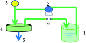 | ||
| Fig. 2 Membrane performance evaluation instrument: (1) feed tank; (2) pump; (3) pressure gauge; (4) membrane cell; (5) permeate end; (6) valve. | ||
The permeation flux of the membrane was calculated using the following equation:
| J = V/(A × t) | (1) |
A conductivity meter (STARTER 3100C, Ohaus, Parsippany, NJ, USA) was used to determine the solute concentrations in the permeate and feed. The dye concentration was measured using a UV-visible spectrophotometer (Agilent 8453, Richardson, TX, USA) at the maximal absorption wavelength of each organic dye. The membrane rejection rate (R) of the dye or salt was calculated as follows:
| R = 100% × (Cf − Cp)/Cf | (2) |
Characterization of Mw cut-off and mean pore size
The Mw cut-off (MWCO) refers to the Mw of the smallest solute that can be intercepted by a membrane. By measuring the retention rate of solutes of different Mw (usually PEG), one can obtain the relationship curve for the retention rate of the membrane and the Mw of the solute. Usually, the Mw of the solute corresponding to a retention rate of 90% on the retention curve is defined as the MWCO of a membrane.19,20The experiment measured the retention performance of the solution to characterize the MWCO of the membrane by measuring PEGs of different Mw (Mw = 400, 600, 800, 1000, and 2000 Da). The concentration of PEG was determined by employing the chromogenic reaction method between PEG and iodine, which was determined from the UV-Vis spectrophotometry.
The following holds true, according to the Stokes–Einstein equation:21
| r = 16.73 × 10⁻³ × Mw0.557 | (3) |
Results and discussion
Preparation of cellulose/chitosan composite nanofiltration membrane by interfacial polymerization
The influence of the aqueous phase PIP concentration, the organic phase TMC concentration, and the time in the aqueous phase and organic phase on the permeability performance of the membrane was tested. The experimental results are as follows.The influence of the aqueous phase PIP concentration on the permeability performance of the membrane
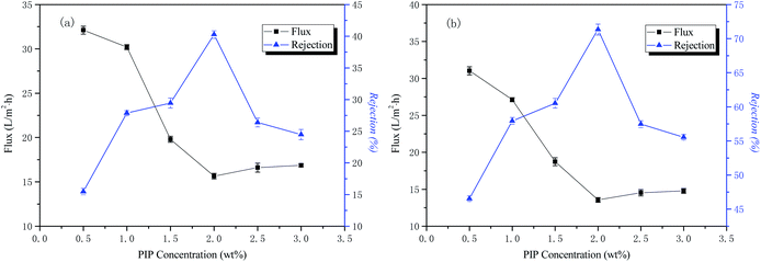
The conditions of the fixed interface polymerization process in this part of the experiment were as follows: 30 min treatment time for the liquid phase, 0.15 wt% TMC concentration for the organic phase, and 3 min reaction time for the organic phase. The influence of the aqueous phase PIP concentration on the permeability performance of the membrane is shown in Fig. 3.The curves of NaCl and Na2SO4 rejection and water flux as a function of the aqueous phase concentration are also shown in Fig. 3. The results indicate that the interception rate of inorganic salts increases rapidly with an increase of the water phase concentration. When the water phase concentration reaches 2 wt%, the interception rate reaches the highest value, the concentration of aqueous phase then increases, and the rejection rate decreases rapidly. The water flux to the inorganic salt solution decreases first and then increases as the concentration of the aqueous phase increases. Both PIP and TMC polymerizations should have a specific molar ratio to produce a perfect network of polymer macromolecules. If the number of moles of PIP is too high, the degree of polymerization of the reaction will be lowered, and it is then difficult to form a perfect network macromolecular structure within a certain period of time. If the number of moles of PIP is too low, water molecules may participate in the reaction, causing the macromolecular end groups to form carboxyl groups, reducing the reactivity and thereby reducing the polymerization degree of the functional layer, as well as making the macromolecular network structure imperfect. The best aqueous phase concentration was 2 wt% in this study.
The influence of time in the aqueous phase on the permeability performance of the membrane
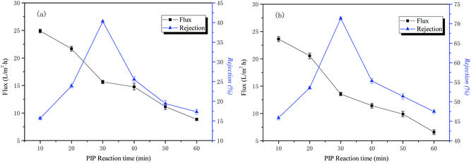
The conditions of the fixed interface polymerization process in this part of the experiment are as follows: 2 wt% PIP concentration for the water phase, 0.15 wt% TMC concentration for the organic phase, and 3 min reaction time for the organic phase. The influence of the time in the aqueous phase on the permeability performance of the membrane is shown in Fig. 4.The curves of NaCl and Na2SO4 rejection and water flux as a function of aqueous phase treatment time are also shown in Fig. 4. The results indicate that the retention rate of inorganic salt increased first and then decreased with an increase of the water treatment time. When the treatment time of the water phase reached 30 min, it reached the maximum, the treatment time of water phase then increased, and the interception rate decreased rapidly. The reason for this is that the degree of cross-linking of the polymer layer is increased, the structure of the macromolecular network is denser, and the rejection rate of the inorganic salt is increased as the reaction proceeds. With the continuing increase of treatment time of the water phase, the polymeric layer is thickened, the surface morphology of the resulting functional layer is poor, and the rejection rate is reduced. The water flux is compacted as the reaction time increases and continues to decrease. The optimal aqueous treatment time in this study was 30 min.
The influence of TMC concentration on the permeability performance of the membrane
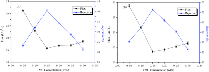
The conditions of the fixed interface polymerization process in this part of the experiment were as follows: 2 wt% PIP concentration for the water phase, 30 min treatment time for the aqueous phase, and 3 min reaction time for the organic phase. The influence of the TMC concentration on the permeability performance of the membrane is shown in Fig. 5.The curves of NaCl and Na2SO4 rejection and water flux as a function of aqueous phase concentration are also shown in Fig. 5. The results indicate that the retention rate of inorganic salts increased rapidly and then decreased with an increase of the organic phase concentration. When the organic phase concentration reached 0.15 wt%, the rejection rate was the highest. This is because, as the concentration of the organic phase increases, the polymerization rate increases, the chemical potential difference of the organic phase TMC increases on both sides of the interface reaction region, and the rate at which TMC diffuses into the reaction region increases, gradually forming a macromolecular network structure that is dense. When the concentration of the organic phase exceeds 0.15 wt%, the rejection rate decreases rapidly and the water flux increases. The reason for this is that the concentration of organic phase is too large, the initial reaction rate is fast, the polymerization layer is rapidly formed, and the thickness is gradually thickened. The resistance of the TMC monomer diffusing into the water phase to participate in the reaction increases, causing the reaction rate to decrease, resulting in a decrease in the density of the final separation layer network. However, it does not affect the diffusion of water molecules into the polymerization layer and reacts with the acid chloride group to form a hydrophilic carboxylic acid group, so the water flux increases and the inorganic salt rejection decreases. The optimum organic phase concentration in this study was 0.15 wt%.
The influence of time in the organic phase on the permeability performance of the membrane
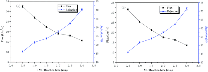
The conditions of the fixed interface polymerization process in this part of the experiment were as follows: 2 wt% PIP concentration for the water phase, 30 min treatment time for the aqueous phase, and 0.15 wt% TMC concentration for the organic phase. The influence of time in the organic phase on the permeability performance of the membrane is shown in Fig. 6.The curves of NaCl and Na2SO4 rejection and water flux as a function of the organic phase reaction time are also shown in Fig. 6. The results indicate that the retention rate of inorganic salts increases with an increase of the interfacial polymerization time, and the water flux to the solution gradually decreases. The reason for this is that as the polymerization time of PIP and TMC increases, the membrane separation layer gradually thickens, and the resulting polyamide functional layer structure tends to be dense, so the nanofiltration membrane water flux is reduced and the rejection rate is increased. Considering the water flux of the nanofiltration membrane, the optimal organic phase reaction time in this study was 3 min.
The influence of operating pressure on the transmission performance of IP-BC/CS-NFM
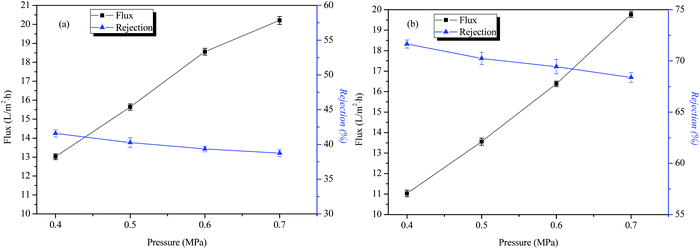
Fig. 7 shows that as the operating pressure increases, the water flux of IP-BC/CS-NFM becomes larger, but the rejection of NaCl and Na2SO4 basically remains unchanged. This result indicates that IP-BC/CS-NFM has a good separation performance under different operating pressure conditions. This phenomenon is the same as other commercial nanofiltration membranes.The permeation and rejection of IP-BC/CS-NFM
IP-BC/CS-NFM was prepared under the above optimum conditions (2 wt% PIP concentration for the water phase, water treatment time of 30 min, 0.15 wt% TMC concentration for the organic phase, and reaction time of 3 min). The filtration performance of the blend nanofiltration membranes of IP-BC/CS-NFM was investigated using five aqueous solutions (NaCl, Na2SO4, MgSO4, MgCl2, Methyl Orange, and Methyl Blue). The water flux and rejection rate results are shown in Table 1. The order of retention of the inorganic salt by IP-BC/CS-NFM is R(Na2SO4) > R(MgSO4) > R(MgCl2) > R(NaCl). The result indicates that the composite nanofiltration membrane has a different filtration performance for different kinds of inorganic salts, leading to a high rejection rate for anionic inorganic salts and a low rejection rate for MgCl2. This phenomenon is the interception feature of the negatively charged nanofiltration membrane.22 The interception of inorganic salts is affected by electrostatic effects and screening effects. The interfacial polymerization separation layer has a greater effect on the intercepting electrostatic effect of inorganic salts than the screening effect. The analysis results indicate that the rejection rate of SO42− was higher than Cl−. The rational reason for this is that the polypiperazine amide complex nanofiltration membrane is negatively charged, and the homologous ions are mutually exclusive and intercepted. A higher valence state of inorganic salt ions leads to a higher rejection rate. Although the hydrate radius of Mg2+ (0.428 nm) is larger than the hydrate radius of Na+ (0.358 nm), the rejection rate of Na2SO4 is greater than MgSO4. This is because the Mg2+ with two positive charges has a stronger shielding effect on IP-BC/CS-NFM, which reduces the effective negative charge density on the surface of the composite nanofiltration membrane.23,24 As the electrostatic repulsion declines, the rejection rate decreases. It is indirectly shown that the interception of inorganic salts by IP-BC/CS-NFM is dominated by an electrostatic repulsion effect, followed by a steric hindrance effect.| Aqueous solutionb | NaCl | Na2SO4 | MgSO4 | MgCl2 | Methyl Orange | Methyl Blue |
|---|---|---|---|---|---|---|
| a Tested with a salt or dye aqueous solution under 0.5 MPa at room temperature.b Tested with de-ionized water containing 500 mg L−1 salt or 100 mg L−1 dye under 0.5 MPa at room temperature. | ||||||
| Water fluxa (L m−2 h−1) | 15.64 ± 0.18 | 13.56 ± 0.20 | 14.03 ± 0.14 | 14.88 ± 0.25 | 13.28 ± 0.22 | 12.35 ± 0.24 |
| Rejection rate (%) | 40.26 ± 0.34 | 71.34 ± 0.56 | 62.55 ± 0.48 | 53.28 ± 0.38 | 93.65 ± 0.58 | 98.86 ± 0.62 |
With the polyethyleneimine/sulfonation of the polyethersulphone (PEI/SPES) composite nanofiltration membrane,25 under the operating pressure of 0.4 MPa at room temperature, and a water flux of the PEI/SPES composite nanofiltration membrane at 5.8 L m−2 h−1, the rejections to Na2SO4 and NaCl were 29% and 18%, respectively. Compared to the PEI/SPES composite nanofiltration membrane, IP-BC/CS-NFM demonstrated better permeation and rejection.
Although Methyl Orange and Methyl Blue are cationic and anionic dyes, respectively, IP-BC/CS-NFM has high rejection rates for Methyl Orange and Methyl Blue. This result indicates that electrostatic effects and sieving effects contribute to the retention performance of the composite nanofiltration membrane.
FT-IR analysis of IP-BC/CS-NFM
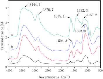
The FT-IR spectra and characteristic absorption peaks of the BC, CS, BC/CSM, and IP-BC/CS-NFM are shown in Fig. 8. Due to the conjugation effect of the carbonyl group and the benzene ring in the polypiperazine trimer amide molecule, the amide I characteristic absorption shifts to a low wavenumber direction and finally appears near 1635.1 cm−1, which is the characteristic peak of the amide (–CONH–). The absorption peak of –NH on the piperazine ring appears at 3444.4 cm−1. The vibration characteristic peak of the benzene ring appears at 1432.3 cm−1. The surface of the BC/CSM is compounded with a polypiperazamide ultrathin separation layer by interfacial polymerization, in which the polypiperazine amide has been formed. These results are consistent with the conclusions obtained by Mansourpanah et al.22 The FT-IR spectra and characteristic absorption peak of IP-BC/CS-NFM appears at 1160.2 cm−1. This result indicates that the pyromellitic acid chloride is acylated with a part of the hydroxyl group in the cellulose. Therefore, the combination of the copolymer layer formed in the interfacial polymerization and the base film is a physical and chemical interaction, which causes the combination to be firmer.Morphology analysis of IP-BC/CS-NFM
The surface and cross-sectional microstructure of BC/CSM and BC/CS-NFMs were characterized by FE-SEM. As observed from Fig. 9(a), the surface microstructure of BC/CSM is uniform. There is no obvious phase separation between BC and CS. The surface microstructure exhibits a sponge-like porous network structure. This phenomenon is mainly due to the formation of NMMO solvent in the membrane during exchange with water. Fig. 9(b) shows that the cross-sectional structure of BC/CSM also exhibits a sponge-like porous network structure. However, its holes are uneven. In the same area, the diffusion rate of the NMMO solvent will affect the size of the internal pore size of the base film. This phenomenon is mainly related to the solvent diffusion rate.26,27 When the solvent is quickly exchanged with water, a large pore structure is formed. Then, the solvent in the interior membrane cannot be exchanged quickly, resulting in the slow liquid–liquid layering speed and porous structure. Fig. 9(c) shows that after the interfacial polymerization of PIP and TMC, the rough polyamide layer formed on the surface of the base film. The pores on the surface of the base film are filled with the polyamide formed by the polymerization. As the interfacial polymerization progresses, a rugged and stacked separation layer is formed, which leads to the base film surface becoming dense. The sectional image of the composite nanofiltration membrane is shown in Fig. 9(d). It can be clearly observed that a uniform, dense, and functional layer is formed on the surface of the base film, which determines the interception characteristics of IP-BC/CS-NFM. The polyamide layer formed by the interfacial polymerization is embedded in the surface of the base film by physical and chemical bonding, which means that the copolymer layer does not easily peel off.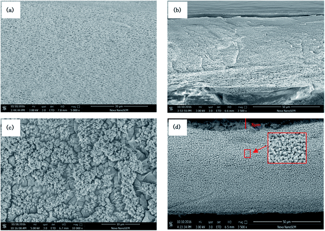 | ||
| Fig. 9 (a) SEM of the BC/CSM surface, (b) SEM of the BC/CSM cross-section, (c) SEM of the IP-BC/CS-NFM surface, (d) SEM of the IP-BC/CS-NFM cross-section. | ||
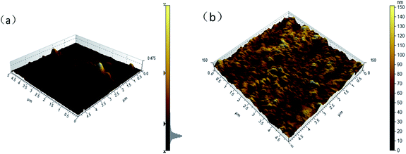
Fig. 10 shows AFM images of BC/CSM and IP-BC/CS-NFM. The results show that the roughness average of BC/CSM and IP-BC/CS-NFM were 2.8 nm, 15.6 nm, respectively. Obviously, as the interfacial polymerization progresses, the surface of nanofiltration membrane becomes rough.
TGA analysis of IP-BC/CS-NFM
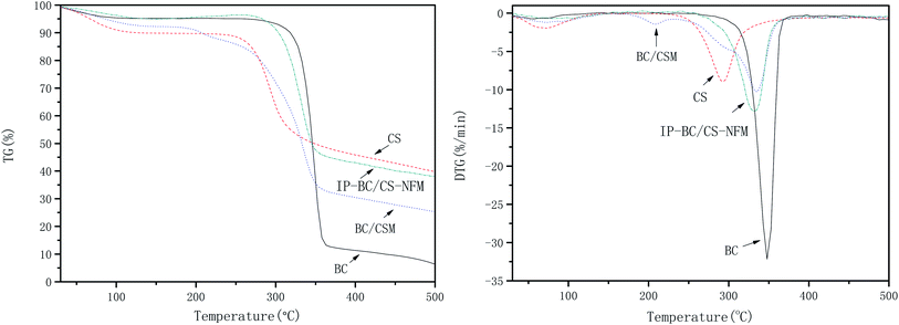
Fig. 11 shows the thermogravimetry (TG) and derivative thermogravimetry (DTG) curves of BC, CS, BC/CSM, and IP-BC/CS-NFM. The results show that the initial decomposition temperatures of BC, CS, BC/CSM, and IP-BC/CS-NFM were 303.0, 245.4, 263.1, and 281.4 °C, respectively. The maximum decomposition rate happened at 347.9, 293.3, 335.5, and 332.2 °C. BC/CSM has a large mass loss of approximately 50.18% from 263.1 to 355.3 °C. The mass loss of IP-BC/CS-NFM was approximately 48.95% from 281.4 to 355.3 °C. These results indicate that the thermal stability of IP-BC/CS-NFM is better than BC/CSM. This phenomenon may be mainly attributed to the –CONH– of polypiperazine amide, which has a strong thermal stability.28,29Mw cut-off and mean pore size of IP-BC/CS-NFM
Due to the weak interaction of the PEG solution with the membrane material, PEG solutions (Mw = 400, 600, 800, 1000, and 2000 Da) were selected to measure the Mw cut-off and pore diameter of the IP-BC/CS-NFM. The retention curve of IP-BC/CS-NFM for different Mw PEGs is shown in Fig. 12. It can be seen from the definition of MWCO that the Mw cut-off of the interfacial polymerized cellulose/chitosan composite nanofiltration membrane is 823 Da. According to Stokes–Einstein's formula (3), the Stokes radius of the nanofiltration membrane is about 0.7 nm.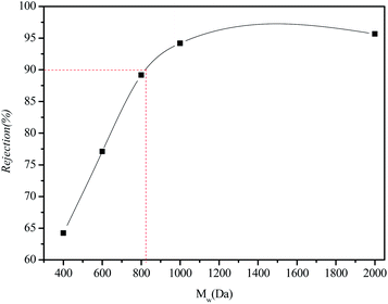 | ||
| Fig. 12 PEG retention curves of IP-BC/CS-NFM. The testing conditions employed were 100 mg L−1 PEG solutions as feed, an operating pressure of 0.5 MPa, and room temperature solution. | ||
Hydrophilicity of BC/CSM and IP-BC/CS-NFM
Fig. 13 shows contact angle of BC/CSM and IP-BC/CS-NFM, are 76.1 ± 0.21° and 61.5 ± 0.16°, respectively. The results show that hydrophilicity of IP-BC/CS-NFM better than BC/CSM. This is because polypiperazine amide itself has a hydrophilic group.Conclusions
In this work, IP-BC/CS-NFM was successfully prepared from cellulose and chitosan in the NMMO solvent. The following conclusions can be drawn from the experimental results.IP-BC/CS-NFM was prepared through the interfacial polymerization of BC/CSM. IP-BC/CS-NFM was prepared under the optimum conditions (2 wt% PIP concentration for the water phase, water treatment time of 30 min, 0.15 wt% TMC concentration for the organic phase, and reaction time of 3 min). IP-BC/CS-NFM was negatively charged on the nanofiltration membrane. The IP-BC/CS-NFM with a pore size of 0.7 nm has a good performance for nanofiltration. At a pressure of 0.5 MPa, the retention rates for NaCl, Na2SO4, MgSO4, MgCl2, Methyl Orange, and Methyl Blue were 40.26%, 71.34%, 62.55%, 53.28%, 93.65%, and 98.86%, and the water flux values were 15.64, 13.56, 14.03, 14.88, 13.28, and 12.35 L m−2 h−1, respectively.
IP-BC/CS-NFM had a characteristic peak of the amide (–CONH–), and the pyromellitic acid chloride was acylated with a part of the hydroxyl groups in the cellulose, which caused the combination to become firmer between the aggregation layer and the base film. The surface and cross-sectional microstructure of BC/CSM exhibited a sponge-like porous network structure. Employing IP-BC/CS-NFM, it could be clearly observed that a uniform, dense, and functional layer was formed on the surface of the base film. The polyamide layer formed by the interfacial polymerization was embedded in the surface of the base film by physical and chemical bonding, which meant that the copolymer layer did not easily peel off. The thermal stability of IP-BC/CS-NFM was better than that of BC/CSM.
The biodegradable, inexpensive, and good separation performance of nanofiltration membranes will be widely used in drinking water treatment, dye wastewater, membrane distillation, food industry, and gas separation applications.
Conflicts of interest
There are no conflicts to declare.Acknowledgements
The authors are grateful for the Education Department of Fujian (JAT170389), the Outstanding Youth Scientific Research Cultivation Plan at Fujian Province University (2017, No.19), the Research Development Foundation of Fujian University of Technology (GY-Z18186), and the Initial Scientific Research Foundation of Fujian University of Technology (GY-Z18063). The authors were supported by the Program for Innovative Research Team in Science and Technology at Fujian Province University.References
- J. Wang, T. F. Huang, L. Zhang, Q. J. Yu and L. A. Hou, Environ. Technol., 2017, 39(23), 1–28 Search PubMed.
- M. B. M. Y. Ang, Y. L. Ji, S. H. Huang, H. A. Tsai, W. S. Hung, C. C. Hu, K. R. Lee and J. Y. Lai, J. Membr. Sci., 2017, 539, 52–64 CrossRef CAS.
- S. S. Li, J. Q. Luo and Y. H. Wan, J. Membr. Sci., 2018, 549, 120–128 CrossRef CAS.
- T. F. Huang, Y. B. Niu, F. Zhang, L. Zhang, S. F. Chen and Q. J. Yu, Applied Materials Today, 2017, 9, 176–183 CrossRef.
- Y. Lv, Y. Du, Z. X. Chen, W. Z. Qiu and Z. K. Xu, J. Membr. Sci., 2018, 545, 99–106 CrossRef CAS.
- Z. W. Chen, J. Q. Luo, X. F. Hang and Y. H. Wan, J. Membr. Sci., 2018, 547, 51–63 CrossRef CAS.
- J. M. Peng, Y. L. Su, W. J. Chen, X. T. Zhao, Z. Y. Jiang, Y. A. Dong, Y. Zhang, J. Z. Liu and X. Z. Cao, J. Membr. Sci., 2013, 427, 92–100 CrossRef CAS.
- M. N. A. Seman, M. Khaye and N. Hilal, J. Membr. Sci., 2010, 348, 109–116 CrossRef.
- M. N. A. Seman, M. Khayet and N. Hilal, Desalination, 2011, 273, 36–47 CrossRef.
- S. Verissimo, K. Peinemann and J. Bordado, J. Membr. Sci., 2005, 264(1–2), 48–55 CrossRef CAS.
- X. H. Ma, Z. Yang, Z. K. Yao, Z. L. Xu and C. Y. Tang, J. Membr. Sci., 2017, 525, 269–276 CrossRef CAS.
- X. K. Lu and X. Y. Shen, Carbohydr. Polym., 2011, 86, 239–244 CrossRef CAS.
- D. Alonso, M. Gimeno and R. Olayo, Carbohydr. Polym., 2009, 7, 536–543 CrossRef.
- S. Lin, L. H. Chen, L. L. Huang, S. L. Cao, X. L. Luo and K. Liu, Ind. Crops Prod., 2015, 70, 395–403 CrossRef CAS.
- Y. C. Xu, Y. P. Tang, L. F. Liu, Z. H. Guo and L. Shao, J. Membr. Sci., 2017, 526, 32–42 CrossRef CAS.
- C. Stefanescu, W. H. Daly and I. I. Negulescu, Carbohydr. Polym., 2012, 87, 435–443 CrossRef CAS.
- Y. Z. Zeng, L. H. Wang, L. Zhang and J. Q. Yu, J. Membr. Sci., 2018, 546, 225–233 CrossRef CAS.
- R. G. Weng, L. H. Chen, S. Lin, H. Zhang, H. Wu, K. Liu, S. L. Cao and L. L. Huang, Polymers, 2017, 9, 116 CrossRef PubMed.
- N. Hilal, M. Al-Abri, H. Al-Hinai and M. Abu-Arabi, Desalination, 2008, 221, 284–293 CrossRef CAS.
- M. Dalwani, N. E. Benes, G. Bargeman, D. Stamatialis and M. Wessling, J. Membr. Sci., 2010, 363, 188–194 CrossRef CAS.
- Q. Yang, T. S. Chung and Y. E. Santoso, J. Membr. Sci., 2007, 290, 153–163 CrossRef CAS.
- Y. Mansourpanah, S. S. Madaeni and A. Rahimpour, J. Membr. Sci., 2009, 343(1–2), 219–228 CrossRef CAS.
- Y. F. Li, Y. L. Su, Y. N. Dong, X. T. Zhao, Z. Y. Jiang, R. N. Zhang and J. J. Zhao, Desalination, 2014, 333(1), 59–65 CrossRef CAS.
- Y. L. Ji, Q. F. An, Q. Zhao, H. L. Chen and C. J. Gao, J. Membr. Sci., 2011, 376, 254–265 CrossRef CAS.
- L. Y. Tan, H. Q. Zhang and J. D. Liu, Asian J. Chem., 2010, 22, 4319–4329 CAS.
- M. A. Shannon, P. W. Bohn, M. Elimelech, J. G. Georgiadis, B. J. Marinas and A. M. Mayes, Nature, 2008, 452, 301–310 CrossRef CAS PubMed.
- C. M. Shih, Y. T. Shieh and Y. K. Twu, Carbohydr. Polym., 2009, 78, 169–174 CrossRef CAS.
- Y. F. Mi, F. Y. Zhao, Y. S. Guo, X. D. Weng, C. C. Ye and Q. F. An, J. Membr. Sci., 2017, 541, 29–38 CrossRef CAS.
- Y. Du, W. Z. Qiu, Y. Lv, J. Wu and Z. K. Xu, ACS Appl. Mater. Interfaces, 2016, 8, 29696–29704 CrossRef CAS PubMed.
| This journal is © The Royal Society of Chemistry 2020 |


